


PNOZ s2
Table of contents
 Loading...
PNOZ s2
Safety relays
Operating Manual-21394-EN-07

Preface
This document is the original document.
All rights to this documentation are reserved by Pilz GmbH & Co. KG. Copies may be made
for internal purposes. Suggestions and comments for improving this documentation will be
gratefully received.
Pilz®, PIT®, PMI®, PNOZ®, Primo®, PSEN®, PSS®, PVIS®, SafetyBUS p®, SafetyEYE®,
SafetyNET p®, the spirit of safety® are registered and protected trademarks of Pilz GmbH
& Co. KG in some countries.
SD means Secure Digital

PNOZ s2
PNOZ s2 safety relay
The safety relay provides a safety-related interruption of a safety circuit.
The safety relay meets the requirements of EN 60947-5-1, EN 60204-1 and VDE 0113-1
and may be used in applications with
} E-STOP pushbuttons
} Safety gates
For your safety
} Only install and commission the unit if you have read and understood these operating
instructions and are familiar with the applicable regulations for health and safety at work
and accident prevention.
Ensure VDE and local regulations are met, especially those relating to safety.
} Any guarantee is rendered invalid if the housing is opened or unauthorised modifica-
tions are carried out.
Unit features
} Positive-guided relay outputs:
– 3 safety contacts (N/O), instantaneous
– 1 auxiliary contact (N/C), instantaneous
} Safe separation of safety contacts from all other circuits
} 1 semiconductor output
} Connection options for:
– E-STOP pushbutton
– Safety gate limit switch
– Start button
} A connector can be used to connect 1 PNOZsigma contact expansion module
} Operating modes can be set via rotary switch
} LED indicator for:
– Supply voltage
– Input status, channel 1
– Input status, channel 2
– Switch status of the safety contacts
} Plug-in connection terminals (either spring-loaded terminal or screw terminal)
Operating Manual PNOZ s2
21394-EN-07
– Start circuit
– Errors
3
PNOZ s2
Safety features
The relay meets the following safety requirements:
} The circuit is redundant with built-in self-monitoring.
} The safety function remains effective in the case of a component failure.
} The correct opening and closing of the safety function relays is tested automatically in
each on-off cycle.
} The unit has an electronic fuse.
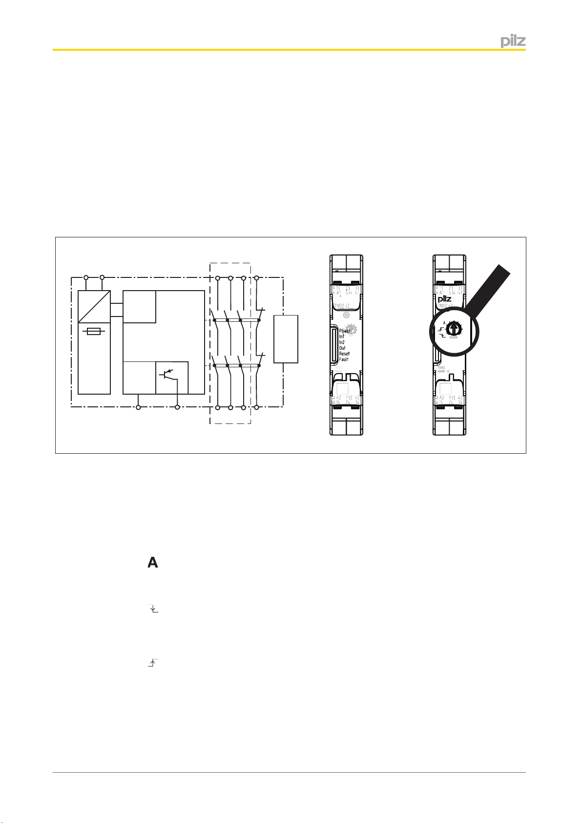
Block diagram/terminal configuration
A1 A2
13
23 33 41
Input
Power
Reset/
Start
S34
Centre: Front view with cover, right: Front view without cover
*Safe separation in accordance with EN 60947-1, 6 kV
Function description
} Single-channel operation: no redundancy in the input circuit, earth faults in the reset
and input circuit are detected.
Y32
K1
K2
14
Interface
24 34 42
unit
expansion
}
} Manual start: Unit is active once the input circuit is closed and then the start circuit is
}
}
} Increase in the number of available instantaneous safety contacts by connecting con-
Operating Manual PNOZ s2
21394-EN-07
Automatic start: Unit is active once the input circuit has been closed.
closed.
Monitored start with falling edge: Unit is active once
– the input circuit is closed and then the start circuit is closed and opened again.
– the start circuit is closed and then opened again once the input circuit is closed.
Monitored start with rising edge: Unit is active once the input circuit is closed and
once the start circuit is closed after the waiting period has elapsed (see technical details).
tact expander modules or external contactors/relays;
A connector can be used to connect 1 PNOZsigma contact expander module.
4

PNOZ s2
Installation
Install base unit without contact expansion module:
} Ensure that the plug terminator is inserted at the side of the unit.
Connect base unit and PNOZsigma contact expansion module:
} Remove the plug terminator at the side of the base unit and at the contact expansion
module.
} Connect the base unit and the contact expansion module to the supplied connector be-
fore mounting the units to the DIN rail.
Installation in control cabinet
} The safety relay should be installed in a control cabinet with a protection type of at least
IP54.
} Use the notch on the rear of the unit to attach it to a DIN rail (35 mm).
} When installed vertically: Secure the unit by using a fixing element (e.g. retaining brack-
et or end angle).
} Push the device upwards or downwards before lifting it from the DIN rail.
Wiring
Please note:
} Information given in the "Technical details" must be followed.
} Outputs 13-14, 23-24, 33-34 are safety contacts; output 41-42 is an auxiliary contact
(e.g. for display).
} Auxiliary contact 41-42 and semiconductor output Y32 should not be used for safety
circuits!
} To prevent contact welding, a fuse should be connected before the output contacts (see
technical details).
} Calculation of the max. cable length l
R
= max. overall cable resistance (see technical details)
lmax
/ km = cable resistance/km
R
l
} Use copper wire that can withstand 60/75 °C.
} Sufficient fuse protection must be provided on all output contacts with capacitive and in-
ductive loads.
in the input circuit:
max
Operating Manual PNOZ s2
21394-EN-07
5
Loading...