


21 255-01 PNOZ mc9p
4 D |
Betriebsanleitung |
4 E |
Instrucciones de uso |
|
4 GB |
Operating instructions |
4 I |
Istruzioni per l`uso |
|
4 F |
Manuel d'utilisation |
4 NL |
Gebruiksaanwijzing |
|
|
|
|
|
|
|
|
|
|
|
Erweiterungsmodul PNOZ mc9p PROFINET IO
Das Erweiterungsmodul PNOZ mc9p darf nur an ein Basisgerät (z. B. PNOZ m1p des modularen Sicherheitssystems PNOZmulti) angeschlossen werden. Es koppelt das modulare Sicherheitssystem PNOZmulti an Steuerungen an, die das Protokoll PROFINET IO unterstützen. Das modulare Sicherheitssystem PNOZmulti dient dem sicherheitsgerichteten Unterbrechen von
Sicherheitsstromkreisen und ist bestimmt für den Einsatz in:
•NOT-AUS-Einrichtungen
•Sicherheitsstromkreisen nach VDE 0113
Teil 1, 11/98 und EN 60204-1, 12/97
(z. B. bei beweglichen Verdeckungen)
Achtung! Das Erweiterungsmodul PNOZ mc9p darf nicht für sicherheitsgerichtete Funktionen verwendet werden.
Lieferumfang:
•Erweiterungsmodul PNOZ mc9p
•Steckbrücke (siehe Abschnitt Ersatzteile)
Zu Ihrer Sicherheit
Beachten Sie nachfolgend aufgeführte
Sicherheitsbestimmungen:
•Installieren und nehmen Sie das Modul nur dann in Betrieb, wenn Sie mit dieser Betriebsanleitung und den geltenden Vorschriften über Arbeitssicherheit und
Unfallverhütung vertraut sind.
•Verwenden Sie das Modul nur gemäß seiner Bestimmung. Beachten Sie dazu auch die Werte im Abschnitt "Technische Daten".
•Halten Sie beim Transport, bei der Lagerung und im Betrieb die Bedingungen nach EN 60068-2-6, 04/95 ein (siehe "Technische Daten").
•Öffnen Sie nicht das Gehäuse und nehmen Sie auch keine eigenmächtigen Umbauten vor.
•Schalten Sie bei Wartungsarbeiten
unbedingt die Versorgungsspannung ab.
Beachten Sie unbedingt die Warnhinweise in den anderen Abschnitten dieser Anleitung. Diese Hinweise sind optisch durch Symbole hervorgehoben.
Wichtig: Beachten Sie die Sicherheitsbestimmungen, sonst erlischt jegliche Gewährleistung.
PNOZ mc9p expansion module PROFINET IO
The PNOZ mc9p expansion module may only be connected to a base unit (e.g. PNOZ m1p from the PNOZmulti modular safety system). It connects the PNOZmulti modular safety system to controls which support the PROFINET IO protocol. The
PNOZmulti modular safety system is used for the safety-related interruption of safety circuits and is designed for use on:
•Emergency stop equipment
•Safety circuits in accordance with
VDE 0113 Part 1, 11/98 and EN 60204-1, 12/97 (e.g. on movable guards)
Caution! The PNOZ mc9p expansion module may not be used for safety-related functions.
Range:
•PNOZ mc9p expansion module
•Jumper (see section entitled "Spares")
For your safety
Please note the following safety regulations:
•Only install and commission the module if you are familiar with both these instructions and the current regulations for health and safety at work and accident prevention.
•Only use the module in accordance with its intended purpose. Please also take note of the values in the "Technical details" section.
•Transport, storage and operating conditions must all conform to EN 60068-2-6, 04/95 (see "Technical details").
•Do not open the housing or undertake any unauthorised modifications.
•Always switch off the supply voltage when carrying out maintenance work.
You must take note of the warnings given in other sections of these operating instructions.
These are highlighted visually through the use of symbols.
Notice: Failure to keep to these safety regulations will render the warranty invalid.
Module d’extension PNOZ mc9p PROFINET IO
Le module d’extension PNOZ mc9p ne doit être raccordé qu’à un appareil de base (par exemple PNOZ m1p du système de sécurité modulaire PNOZmulti). Il permet de coupler le système de sécurité modulaire PNOZmulti à des automates qui supportent le procotole PROFINET IO. Le système de sécurité modulaire PNOZmulti est conçu pour interrompre en toute sécurité des circuits de sécurité et être utilisé dans les applications suivantes :
•Circuits d’arrêt d’urgence
•Circuits de sécurité selon les normes
VDE 0113-1, 11/98 et EN 60204-1, 12/97
(p. ex. pour protections mobiles)
Attention ! Le module d’extension PNOZ mc9p ne doit pas être utilisé pour des fonctions de sécurité.
Contenu de la livraison :
•Module d’extension PNOZ mc9p
•Cavalier de pontage (voir partie "Pièces de rechange")
Pour votre sécurité
Vous êtes tenu de respecter les prescriptions de sécurité suivantes :
•Vous n’installerez le module et ne le mettrez en service qu’après vous être familiarisé avec le présent manuel d’utilisation et les prescriptions en vigueur sur la sécurité du travail et la prévention des accidents.
•N’utilisez le module que conformément à l’usage auquel il est destiné. À ce sujet, respectez les valeurs indiquées dans les
"Caractéristiques techniques".
•Pour le transport, le stockage et l’utilisation, respectez les exigences de la norme EN 60068-2-6, 04/95 (voir "Caractéristiques techniques").
•N’ouvrez pas le boîtier et n’effectuez pas de modifications non autorisées.
•Lors de l’exécution de travaux de
maintenance, coupez impérativement la tension d’alimentation.
Respectez impérativement les avertissements dans les autres paragraphes du présent manuel d’utilisation. Ces avertissements sont signalés par des symboles visuels.
Important : Respectez les consignes de sécurité, sinon la garantie devient caduque.
Systemvoraussetzungen |
System requirements |
Configuration du système requise |
|
• |
Basisgerät PNOZ m0p |
• Base unit PNOZ m0p |
• Appareil de base PNOZ m0p |
|
ab Version 2.2 |
from Version 2.2 |
à partir de la version 2.2 |
• |
Basisgerät PNOZ m1p |
• Base unit PNOZ m1p |
• Appareil de base PNOZ m1p |
|
ab Version 5.2 |
from Version 5.2 |
à partir de la version 5.2 |
• |
Basisgerät PNOZ m2p |
• Base unit PNOZ m2p |
• Appareil de base PNOZ m2p |
|
ab Version 2.2 |
from Version 2.2 |
à partir de la version 2.2 |
- 1 -
•PNOZmulti Configurator: ab Version 5.0.0
•Wenn Sie eine ältere Version besitzen, wenden Sie sich bitte an Pilz.
Modulbeschreibung
PROFINET IO ist konzipiert für den schnellen Datenaustausch in der Feldebene. Das
Erweiterungsmodul PNOZ mc9p ist ein passiver Teilnehmer des PROFINET IO. Die Grundfunktionen der Kommunikation mit PROFINET IO entsprechen der Systembeschreibung der PROFIBUS Nutzerorganisation.
Die zentrale Steuerung (Master) liest zyklisch die Eingangsinformationen von den Slaves und schreibt die Ausgangsinformationen zyklisch an die Slaves.
Modulmerkmale:
•konfigurierbar mit PNOZmulti Configurator
•Netzwerkprotokolle: PROFINET IO
•Statusanzeigen für Kommunikation und von Fehlern
•Übertragungsrate 100 MBit/s (100BaseTX), Vollund Halbduplex
Funktionsbeschreibung
Arbeitsweise:
Die über PROFINET IO zu übertragenden
Daten werden im PNOZmulti Configurator ausgewählt und konfiguriert.
Die Verbindung zwischen Basisgerät und dem PNOZ mc9p erfolgt über eine Steckbrücke. Über diese Steckbrücke wird das PNOZ mc9p auch mit Spannung versorgt.
Nach Einschalten der Versorgungsspannung oder einem Reset des Sicherheitssystems
PNOZmulti wird das PNOZ mc9p automatisch konfiguriert und gestartet.
Funktionen:
LEDs zeigen den Status des Erweiterungsmoduls PNOZ mc9p am PROFINET IO an.
INFO
In der Online-Hilfe des PNOZmulti Configurators ist die Konfiguration des PNOZ mc9p ausführlich beschrieben.
•PNOZmulti Configurator: from Version 5.0.0
•Please contact Pilz if you have an older version.
Module description
PROFINET IO is designed for fast data exchange at field level. The PNOZ mc9p expansion module is a passive PROFINET IO subscriber. The basic functions of the communication with PROFINET IO conform to the system description of the PROFIBUS user organisation.
The central controller (master) reads input information from the slaves and writes output information to the slaves as part of each cycle.
Module features:
•Can be configured using the PNOZmulti Configurator
•Network protocols: PROFINET IO
•Status indicators for communication and for errors
•Transmission rate 100 MBit/s (100BaseTX), full and half duplex
Function description
Operation:
The data to be transferred via the
PROFINET IO is selected and configured in the PNOZmulti Configurator. The base unit and the PNOZ mc9p are connected via a jumper.
The PNOZ mc9p is also supplied with voltage via this jumper. After the supply voltage is switched on or the PNOZmulti safety system is reset, the PNOZ mc9p is configured and started automatically.
Functions:
LEDs indicate the status of the PNOZ mc9p expansion module on the PROFINET IO.
INFORMATION
The configuration of the PNOZ mc9p is described in detail in the PNOZmulti Configurator’s online help.
•Configurateur PNOZmulti :
à partir de la version 5.0.0
•Si vous possédez une version antérieure, veuillez vous adresser à Pilz.
Description du module
PROFINET IO est conçu pour un échange rapide de données sur le terrain. Le module d’extension PNOZ mc9p est un abonné passif de PROFINET IO. Les fonctions de base de la communication avec PROFINET IO sont conformes à la description du système de l’association des utilisateurs PROFIBUS.
Le système central (maître) lit cycliquement les informations d’entrée sur les esclaves et écrit cycliquement les informations de sortie dans les esclaves.
Caractéristiques du module :
•Paramétrable avec le configurateur PNOZmulti
•Protocoles de réseau : PROFINET IO
•Affichage d’état pour la communication et pour les erreurs
•Vitesse de transmission : 100 Mbit/s (100BaseTX), duplex intégral et semiduplex
Descriptif du fonctionnement
Mode de travail :
Les données à transmettre par
PROFINET IO sont sélectionnées et configurées dans le configurateur PNOZmulti. La liaison entre l’appareil de base et le
PNOZ mc9p est réalisée au moyen d’un cavalier de pontage. Celui-ci assure également l’alimentation en tension du
PNOZ mc9p. Après application de la tension d’alimentation ou une réinitialisation du système de sécurité PNOZmulti, le PNOZ mc9p est automatiquement configuré et démarré.
Fonctions :
Les LED indiquent l’état du module d’extension PNOZ mc9p sur le réseau
PROFINET IO.
INFORMATION
La configuration du module
PNOZ mc9p est décrite en détail dans l’aide en ligne du configurateur
PNOZmulti.
MOD |
|
|
COM |
|
STAT |
ACT STAT |
|||
|
|
|
|
|
|
|
|
|
|
DC |
DC |
PROFINET
Controller |
m1p |
|
PNOZ |
||
|
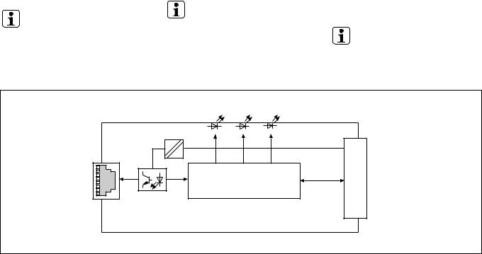
Innenschaltbild |
Internal wiring diagram |
Schéma interne |
- 2 -

PNOZ mc9p montieren
Beachten Sie bei der Montage:
Achtung! Durch elektrostatische
Entladung können Bauteile der Sicherheitssteuerung beschädigt werden. Sorgen Sie für Entladung, bevor Sie die Sicherheitssteuerung berühren, z. B. durch Berühren einer geerdeten, leitfähigen Fläche oder durch Tragen eines geerdeten Armbands.
•Montieren Sie das Sicherheitssystem in einen Schaltschrank mit einer Schutzart von mindestens IP54.
•Montieren Sie das Sicherheitssystem auf eine waagrechte Tragschiene. Die Lüftungsschlitze müssen nach oben und unten zeigen (siehe Betriebsanleitung des
Basisgeräts). Andere Einbaulagen können zur Zerstörung des Sicherheitssystems führen.
•Befestigen Sie das Sicherheitssystem mit
Hilfe der Rastelemente auf der Rückseite auf einer Normschiene. Führen Sie das Sicherheitssystem gerade auf die Normschiene, so dass die Erdungsfedern am Sicherheitssystem auf die Normschiene gedrückt werden.
•Um die EMV-Anforderungen einzuhalten, muss die Normschiene mit dem Schaltschrankgehäuse niederohmig verbunden sein.
Basisgerät und Erweiterungsmodule verbinden
Die Module werden mit Steckbrücken verbunden. Es dürfen max. 8 Erweiterungsmodule und ein Feldbusmodul an ein Basisgerät angeschlossen werden.
Auf der Geräterückseite des Basisgeräts befinden sich 2 Stiftleisten.
•Stellen Sie sicher, dass kein Abschlussstecker gesteckt ist.
•Verbinden Sie das Basisgerät, die
Erweiterungsmodule und das Feldbusmodul mit den mitgelieferten Steckbrücken.
•Stecken Sie den Abschlussstecker auf das letzte Erweiterungsmodul.
•Zwischen dem PNOZ mc9p und externen Wärmequellen muss mind. 20 mm Abstand eingehalten werden.
Installing the PNOZ mc9p
Please note for installation:
Caution! Electrostatic discharge can damage components on the safety system. Ensure discharge before touching the safety system, e.g. by touching an earthed, conductive surface or by wearing an earthed armband.
•The safety system should be installed in a control cabinet with a protection type of at least IP54.
•Fit the safety system to a horizontal DIN rail. The venting slots must point up and down (see operating instructions for the base unit). Other mounting positions could damage the safety system.
•Use the notches on the back of the safety system to attach it to a DIN rail. Connect the safety system to the DIN rail in an upright position so that the earthing springs on the safety system are pressed on to the DIN rail.
•To comply with EMC requirements, the DIN rail must have a low impedance connection to the control cabinet housing.
Connecting the base unit and expansion modules
The modules are linked via jumpers. A max. of 8 expansion modules plus one fieldbus module may be connected to one base unit.
There are 2 pin connectors on the rear of the base unit.
•Ensure that no terminator is connected.
•Connect the base unit, the expansion modules and the fieldbus module using the jumpers supplied.
•The terminator must be fitted to the last expansion module.
•A distance of at least 20 mm must be maintained between the PNOZ mc9p and any external heat sources.
Installer le PNOZ mc9p
Pour le montage, respectez les consignes suivantes :
Attention ! Une décharge électrostatique peut endommager les éléments de l’automate de sécurité. Veillez à vous décharger avant de toucher l’automate de sécurité, par exemple en touchant une surface conductrice mise à la terre ou en portant un bracelet de mise à la terre.
•Montez le système de sécurité dans une armoire d’indice de protection IP 54 au moins.
•Montez le système de sécurité sur un profilé support horizontal. Les ouïes de ventilation doivent être orientées vers le haut et vers le bas (voir le manuel d’utilisation de l’appareil de base). D’autres positions de montage pourraient aboutir à une destruction du système de sécurité.
•Montez le système de sécurité sur un rail
DIN à l’aide du système de fixation situé au dos de l’appareil. Installez le système de sécurité droit sur le rail DIN de sorte que les ressorts de mise à la terre sur le système de sécurité reposent sur le rail
DIN.
•Pour répondre aux exigences CEM, le rail
DIN doit être relié au corps de l’armoire électrique par une liaison à basse impédance.
Relier l’appareil de base et les modules d’extension
Les modules sont reliés par des cavaliers de pontage. Huit modules d’extension et un module de bus de terrain au maximum peuvent être reliés à un appareil de base. La face arrière de l’appareil de base comporte 2 broches.
•Assurez-vous qu’aucune fiche de terminaison n’est branchée.
•Reliez l’appareil de base, les modules d’extension et le module de bus de terrain avec les cavaliers de pontage livrés avec les appareils.
•Branchez la fiche de terminaison sur le dernier module d’extension.
•Une distance d’au moins 20 mm doit être respectée entre le PNOZ mc9p et les sources de chaleur externes.
PNOZ mc9p links vom Basisgerät |
Install the PNOZ mc9p to the left of the |
||||||||||||||
montieren! |
|
base unit! |
|
|
|
||||||||||
Feldbusmodul |
Basisgerät |
|
Erweiterungsmodul 1 |
||||||||||||
Fieldbus module |
Base unit |
|
|
Expansion module 1 |
|||||||||||
Module de bus de terrain |
Appareil de base |
|
Module d'extension 1 |
||||||||||||
|
|
|
|
|
|
|
|
|
|
|
|
|
|
|
|
|
|
|
|
|
|
|
|
|
|
|
|
|
|
|
|
|
|
|
|
|
|
|
|
|
|
|
|
|
|
|
|
|
|
|
|
|
|
|
|
|
|
|
|
|
|
|
|
|
|
|
|
|
|
|
|
|
|
|
|
|
|
|
|
|
|
|
|
|
|
|
|
|
|
|
|
|
|
|
|
Monter le PNOZ mc9p à gauche de l’appareil de base !
Erweiterungsmodul 8
Expansion module 8
Module d'extension 8
|
|
|
|
|
|
|
|
|
|
|
|
|
|
|
|
|
|
|
|
|
|
|
|
|
|
|
|
|
|
|
|
|
|
|
|
|
|
|
|
|
|
|
|
|
|
|
|
|
|
|
|
|
|
|
|
|
|
|
|
|
|
|
|
|
|
|
|
|
|
|
|
|
|
|
|
|
|
|
|
|
|
|
|
|
|
|
|
|
|
|
|
|
|
|
|
|
|
|
|
|
|
|
|
|
|
|
|
|
|
|
|
|
|
|
|
|
|
|
|
|
|
|
|
|
|
|
|
|
|
|
|
|
|
|
|
|
|
|
|
|
|
|
|
|
|
|
|
|
|
|
|
|
|
|
|
|
|
|
|
|
|
|
|
|
|
|
|
|
|
|
|
|
|
|
|
|
|
|
|
|
|
|
|
|
|
|
|
|
|
|
|
|
|
|
|
|
|
|
|
|
|
|
|
|
|
|
|
|
|
|
|
Steckbrücke |
Abschlussstecker |
|
|
|||||||||||||||
|
|
|
|
|
|
|
|
|
|
|
||||||||||||||||||||||
|
|
|
|
|
|
|
|
|
|
|
|
|
|
Jumper |
Terminator |
|
|
|||||||||||||||
|
|
|
|
|
|
|
|
|
|
|
|
|
|
Cavalier de pontage |
Fiche de terminaison |
|
|
|||||||||||||||
PNOZ mc9p montieren |
|
|
|
|
|
Installing the PNOZ mc9p |
Installer le PNOZ mc9p |
|
|
|||||||||||||||||||||||
- 3 -
Achtung! Verwenden Sie nur
Steckbrücken und Abschlussstecker mit den folgenden Bestellnummern: Steckbrücken: 774 639 Abschlussstecker: 779 110
PNOZ mc9p inbetriebnehmen
Inbetriebnahme vorbereiten:
Beachten Sie bei der Vorbereitung der Inbetriebnahme:
Achtung! Das Erweiterungsmodul PNOZ mc9p nur im spannungslosen Zustand ziehen und stecken.
Wichtig: Beachten Sie bei der
Installation unbedingt die Anforderungen der Installationsrichtlinie PROFINET der PROFIBUS Nutzerorganisation.
•Die folgenden Mindestanforderungen an die Verbindungskabel und Stecker müssen erfüllt werden:
-Verwenden Sie ausschließlich industrietaugliche Ethernet-Kabel und Stecker.
-Verwenden Sie ausschließlich doppelt abgeschirmtes Twisted Pair-Kabel und geschirmte RJ45-Stecker (IndustrieStecker).
-100BaseTX-Kabel nach EthernetStandard (min. Kategorie 5)
•Störschutzmaßnahmen
Beachten Sie die Anforderungen für den industriellen Einsatz von PROFINET IO.
Betriebsbereitschaft herstellen:
•Gerätename vergeben
-Der Gerätename wird im PNOZmulti Configurator vergeben.
Geben Sie bei der Auswahl des PNOZ mc9p den Gerätenamen in das
Feld Betriebsmittelkennzeichen ein.
-Sie können den Gerätenamen auch durch den IO Controller vergeben. In diesem Fall fügen Sie im PNOZmulti Configurator vor dem Gerätenamen im
Feld Betriebsmittelkennzeichen das Zeichen „$“ ein.
-Der Gerätename am Ethernet-Subnetz muss eindeutig sein. Er muss der DNSKonvention entsprechen:
-max. 127 Zeichen (Buchstaben, Ziffern, Bindestrich oder Punkt)
-max. 63 Zeichen zwischen zwei
Punkten
-Unzulässig sind Zeichen wie folgt:
ä ö ü ( ) _ / Leerzeichen Der Gerätename darf nicht
-mit dem Zeichen „-“ beginnen oder enden.
-die Form n.n.n.n (n = 0 ... 999) haben.
-mit der Zeichenfolge „port-xyz-“ (x, y, z = 0 ... 9) beginnen.
•GSD-Datei installieren
Installieren Sie die GSD-Datei in Ihrer
Konfigurationssoftware. Erst dann steht
Ihnen das PNOZ mc9p zur Verfügung.
•Legen Sie die Versorgungsspannung an das Basisgerät:
Klemmen 24 V und A1 (+): + 24 V DC Klemmen 0 V und A2 (-): 0 V
Caution! Use only jumpers and terminators with the following order numbers:
Jumpers: 774 639 Terminators: 779 110
Commissioning the PNOZ mc9p
Preparing for commissioning:
Please note the following when preparing to commission the unit:
Caution! Only connect and disconnect the PNOZ mc9p expansion module when the supply voltage is switched off.
Important: Be sure to note the PROFIBUS User Group PROFINET Installation Manual requirements during installation.
•The following minimum requirements for connection cables and connectors must be met:
-Only use standard industrial Ethernet cable and connectors.
-Only use double-shielded twisted pair cable and shielded RJ45 connectors (industrial).
-10BaseT or 100BaseTX cable in accordance with the Ethernet standard (min. Category 5)
•Measures to protect against interference Ensure the requirements for the industrial use of PROFINET IO.
Preparing for operation:
•Assign unit name
-The unit name is assigned in the PNOZmulti Configurator.
Enter the unit name in the Equipment identifier field when selecting the
PNOZ mc9p.
-You can also assign the unit name through the IO Controller. In this case, insert a "$" symbol in front of the unit name in the Equipment identifier field in the PNOZmulti Configurator.
-The unit name on the Ethernet subnet must be unique. It must comply with the
DNS conventions:
-max. 127 characters (letters, numbers, hyphen or period)
-max. 63 characters between two periods
-the following characters are invalid:
( ) _ / space
The unit name may not
-begin or end with the "-" character.
-have the form n.n.n.n (n = 0 - 999).
-begin with the character string "port- xyz-" (x, y, z = 0 - 9).
•Install GSD file
Install the GSD file in your configuration software. You can only then use the
PNOZ mc9p.
•Connect the supply voltage to the base unit:
Terminals 24 V and A1 (+): + 24 VDC
Terminals 0 V and A2 (-): 0 V
Attention ! N’utilisez que des cavaliers de pontage et des fiches de terminaison portant les références suivantes :
Cavaliers de pontage : 774 639
Fiches de terminaison : 779 110
Mettre en service le PNOZ mc9p
Préparation de la mise en service :
Pour préparer la mise en service, respectez les consignes suivantes :
Attention ! Le module d’extension PNOZ mc9p ne doit être mis en place ou retiré que lorsqu’il est hors tension.
Important : Lors de l’installation, respectez impérativement les exigences indiquées dans la directive d’installation PROFINET de l’association des utilisateurs PROFIBUS.
•Les exigences minimales posées aux câbles de raccordement et aux connecteurs doivent être remplies :
-Utilisez exclusivement des câbles et connecteurs Ethernet prévus pour un usage industriel.
-Utilisez exclusivement un câble à paires torsadées à double blindage et des connecteurs RJ45 blindés (connecteurs industriels).
-Câble 10BaseT ou 100BaseTX selon la norme Ethernet (minimum catégorie 5)
•Mesures de protection antiparasitage Respectez les exigences applicables à l’utilisation industrielle d’PROFINET IO.
Mise en route :
•Attribuer le nom de l’appareil
-L’attribution du nom de l’appareil s’effectue dans le PNOZmulti
Configurator.
Lors de la sélection du PNOZ mc9p, saisissez le nom de l’appareil dans le champ Identification équipement.
-Vous pouvez également attribuer le nom de l’appareil à l’aide du IO Controller. Dans ce cas, tapez le caractère "$" devant le nom de l’appareil dans le champ Identification équipement du PNOZmulti Configurator.
-Le nom de l’appareil sur le sous-réseau Ethernet doit être unique. Il doit être conforme à la convention DNS :
-127 caractères au maximum (lettres, chiffres, tiret ou point)
-63 caractères au maximum entre deux points
-Sont interdits les caractères tels que : accents ( ) _ / espaces
Le nom de l’appareil ne doit pas
-commencer ou se terminer par le caractère "-".
-avoir la forme n.n.n.n (n = 0 à 999).
-commencer par la chaîne de caractères "port-xyz-" (x, y, z = 0 à 9).
•Installer le fichier GSD
Installez le fichier GSD dans votre logiciel de configuration. Le PNOZ mc9p n’est disponible qu’au terme de ces opérations.
•Appliquez la tension d’alimentation sur l’appareil de base :
Bornes 24 V et A1 (+) : + 24 V DC
Bornes 0 V et A2 (-) : 0 V
- 4 -

•IP-Adresse vergeben
Es bestehen zwei Möglichkeiten:
-Automatische Vergabe der IP-Adresse mit dem Dynamic Host Configuration Protocol (DHCP)
-Vergabe der IP-Adresse vom
IO Controller vor dem Systemhochlauf aufgrund des eindeutigen Gerätenamens.
Betrieb
•Assign IP address
There are two options:
-Automatic assignment of the IP address with the Dynamic Host Configuration Protocol (DHCP)
-Assignment of the IP address by the
IO Controller before system startup based on the unique unit name.
Operation
Nach Einschalten der Versorgungsspannung oder einem Reset des Sicherheitssystems
PNOZmulti wird das PNOZ mc9p automatisch konfiguriert und gestartet. Die LEDS "ACT", "COM STAT" und "MOD STAT" zeigen den Status des PNOZ mc9p am PROFINET IO an.
LED-Anzeige
LED aus/off/éteinte
LED leuchtet/on/allumée
LED blinkt/flashes/clignotante
1
2
3
4
After the supply voltage is switched on or the PNOZmulti safety system is reset, the PNOZ mc9p is configured and started automatically.
The "ACT", "COM STAT" and "MOD STAT" LEDs indicate the status of the PNOZ mc9p on the PROFINET IO.
LEDs
•Attribuer l’adresse IP
Il existe deux possibilités :
-Attribution automatique de l’adresse IP par le Dynamic Host Configuration Protocol (DHCP)
-Attribution de l’adresse IP par le
IO Controller avant le démarrage du système en raison d’un nom d’appareil unique.
Fonctionnement
Après application de la tension d’alimentation ou une réinitialisation du système de sécurité
PNOZmulti, le PNOZ mc9p est automatiquement configuré et démarré. Les LEDs "ACT", "COM STAT" et "MOD STAT" indiquent l’état du PNOZ mc9p sur le réseau PROFINET IO.
LEDs de visualisation
LED
ACT
COM
STAT
MOD
STAT
LED-Zustand |
Bedeutung |
Meaning |
Signification |
|||||
LED status |
|
|
|
|||||
état de la LED |
|
|
|
|||||
|
|
|
|
|
|
|
|
|
|
|
|
|
|
grün/green/ |
Busverbindung vorhanden |
Bus connection available |
Connexion de bus disponible |
|
|
|
|
|
vert |
|
|
|
|
|
|
|
|
|
|
|
|
|
|
|
|
|
grün/green/ |
Daten senden/empfangen |
Send/receive data |
Envoi/réception de données |
|
|
|
|
|
||||
|
|
|
|
|
vert |
|
|
|
|
|
|
|
|
|
|
|
|
|
|
|
|
|
|
|
|
|
|
|
|
|
|
|
keine Busverbindung vorhanden |
Bus connection is not available or |
Aucune connexion de bus existante |
|
|
|
|
|
|
oder Versorgungsspannung fehlt |
supply voltage is missing |
ou tension d’alimentation manquante |
|
|
|
|
|
|
|
|
|
|
|
|
|
|
grün/green/ |
Online, Run |
Online, RUN |
En ligne, Run |
|
|
|
|
|
vert |
- Verbindung mit IO Controller |
- Connection with IO Controller |
- Connexion existante avec |
|
|
|
|
|
|
vorhanden |
available |
IO Controller |
|
|
|
|
|
|
- IO Controller im Run |
- IO Controller in RUN |
- IO Controller en Run |
1 |
|
|
|
|
grün/green/ |
Online, STOP |
Online, STOP |
En ligne, STOP |
|
|
|
|
|||||
|
|
|
|
vert |
- Verbindung mit IO Controller |
- Connection with IO Controller |
- Connexion existante avec |
|
|
|
|
|
|
||||
|
|
|
|
|
|
vorhanden |
available |
IO Controller |
|
|
|
|
|
|
- IO Controller im STOP |
- IO Controller in STOP |
- IO Controller en STOP |
|
|
|
|
|
|
Offline, STOP |
Offline, STOP |
Hors ligne, STOP |
|
|
|
|
|
|
- keineVerbindung mit |
- Connection with IO Controller not |
- Aucune connexion existante avec |
|
|
|
|
|
|
IO Controller vorhanden |
available |
IO Controller |
|
|
|
|
|
|
|
|
|
|
|
|
|
|
grün/green/ |
initialisiert, kein Fehler |
Initialised, no fault |
Initialisé, aucune erreur |
|
|
|
|
|
vert |
|
|
|
|
|
|
|
|
|
|
|
|
1 |
|
|
|
|
grün/green/ |
Diagnosedaten verfügbar |
Diagnostic data available |
Données de diagnostic disponibles |
|
|
|
|
vert |
|
|
|
|
|
|
|
|
|
|
|
|
|
|
|
|
|
|
|
|
|
|
2 |
|
|
|
|
grün/green/ |
PNOZ mc9p wird identifiziert |
PNOZ mc9p is identified |
Identification du PNOZ mc9p en cours |
|
|
|
|
vert |
|
|
|
|
|
|
|
|
|
|
|
|
|
|
|
|
|
|
|
|
|
|
1 |
|
|
|
|
rot/red/ |
Fehler der Konfiguration |
Configuration error |
Erreur de configuration |
|
|
|
|
|||||
|
|
|
|
rouge |
- zu viele Module/Submodule |
- Too many modules/submodules |
- Trop de modules/sous-modules |
|
|
|
|
|
|
||||
|
|
|
|
|
|
- I/O-Bereich der IO Controller- |
- I/O range of IO Controller |
- La plage I/O de la configuration |
|
|
|
|
|
|
Konfiguration ist zu groß |
configuration is too big |
IO Controller est trop importante |
|
|
|
|
|
|
- Fehlerhafte Konfiguration (kein |
- Faulty configuration (no module, |
- Configuration erronée (aucun |
|
|
|
|
|
|
Modul, falsches Modul) |
incorrect module) |
module, mauvais module) |
3 |
|
|
|
|
rot/red/ |
kein Gerätename oder keine IP- |
No unit name or no IP address |
Aucun nom d’appareil ou aucune |
|
|
|
|
|||||
|
|
|
|
rouge |
Adresse zugewiesen |
assigned |
adresse IP attribué(e) |
|
|
|
|
|
|
||||
4 |
|
|
|
|
rot/red/ |
Interner Fehler |
Internal error |
Erreur interne |
|
|
|
|
|||||
|
|
|
|
rouge |
|
|
|
|
|
|
|
|
|
|
|
|
|
|
|
|
|
|
|
|
|
|
|
|
|
|
|
|
keine Versorgungsspannung oder |
No supply voltage or unit is not |
Aucune tension d’alimentation ou |
|
|
|
|
|
|
Gerät ist nicht initialisiert |
initialised |
appareil non initialisé |
|
|
|
|
|
|
|
|
|
- 5 -
 Loading...