


19894-6NL-06 PNOZ X4
4 D |
Betriebsanleitung |
4 E |
Instrucciones de uso |
|
4 GB |
Operating instructions |
4 I |
Istruzioni per l`uso |
|
4 F |
Manuel d'utilisation |
4 NL |
Gebruiksaanwijzing |
|
|
|
|
|
|
|
|
|
|
|
 Sicherheitsbestimmungen
•Das Gerät darf nur von einer Elektrofachkraft oder unterwiesenen Personen installiert und in Betrieb genommen werden, die mit dieser Betriebsanleitung und den geltenden Vorschriften über Arbeitssicherheit und Unfallverhütung vertraut sind. Beachten Sie die VDEsowie die örtlichen Vorschriften, insbesondere hinsichtlich Schutzmaßnahmen.
•Halten Sie beim Transport, der Lagerung und im Betrieb die Bedingungen nach EN 60068-2-6 ein (siehe technische Daten). Entsorgen Sie das Gerät nach
Ablauf seiner Lebensdauer sachgerecht.
•Durch Öffnen des Gehäuses oder eigenmächtige Umbauten erlischt jegliche Gewährleistung.
•Sorgen Sie an allen Ausgangskontakten bei kapazitiven und induktiven Lasten für eine ausreichende Schutzbeschaltung.
•Hinweis für Überspannungskategorie III: Wenn am Gerät höhere Spannungen als
Kleinspannung (>50 V AC oder >120 V DC) anliegen, müssen ange-
schlossene Bedienelemente und Sensoren eine Bemessungsisolationsspannung von mind. 250 V aufweisen.
Safety Regulations
•The unit may only be installed and commissioned by a competent, qualified electician or personnel instructed accordingly, who are familiar with both these operating instructions and the current regulations for health and safety at work and accident prevention. Follow VDE and local regulations especially regarding preventive measures
•Transport, storage and operating conditions should all conform to EN 60068- 2-6.
At the end of its lifecycle, dispose of the unit in an environmentally safe way and according to any relevant regulations
•Any guarantee is void if the unit is opened or unauthorised modifications have been carried out
•Adequate protection must be provided on all output contacts especially with capacitive and inductive loads.
•Note for overvoltage category III:
If voltages higher than low voltage (>50 VAC or >120 VDC) are present on
the unit, connected control elements and sensors must have a rated insulation voltage of at least 250 V.
Conseils préliminaires
•La mise en oeuvre de l’appareil doit être effectuée par une personne spécialisée en installations électriques, en tenant compte des prescriptions des différentes normes applicables (NF, EN, VDE...) notamment au niveau des risques encourus en cas de défaillance de l’équipement électrique.
•Respecter les exigences de la norme
EN 60068-2-6 lors du transport, du stockage et de l'utilisation de l'appareil (voir caractéristiques techniques). Recycler l'appareil au bout de sa durée de vie conformement aux prescriptions.
•L’ouverture de l’appareil ou sa modification annule automatiquement la garantie.
•Vérifiez que le pouvoir de coupure des contacts de sortie est suffisant en cas de circuits capacitifs ou inductifs.
•Remarque relative à la catégorie de surtensions III :
Si l’appareil est alimenté avec des tensions supérieures à la basse tension (>50 V AC ou >120 V DC), les éléments de commande et les capteurs raccordés doivent supporter une tension d’isolement assignée d’au moins 250 V.
Bestimmungsgemäße Verwendung |
Intended Application |
Domaines d’utilisation |
|||
Das Sicherheitsschaltgerät dient dem |
The safety relay provides a safety-related |
Le bloc logique de sécurité sert à |
|||
sicherheitsgerichteten Unterbrechen eines |
interruption of a safety circuit. |
interrompre en toute sécurité un circuit de |
|||
Sicherheitsstromkreises. |
The safety relay meets the requirements of |
sécurité. |
|||
Das Sicherheitsschaltgerät erfüllt Forderun- |
EN 60947-5-1, EN 60204-1 and VDE 0113- |
Le bloc logique de sécurité satisfait aux |
|||
gen der EN 60947-5-1, EN 60204-1 und |
1 and may be used in applications with |
exigences des normes EN 60947-5-1, |
|||
VDE 0113-1 und darf eingesetzt werden in |
• E-STOP pushbuttons |
EN 60204-1 et VDE 0113-1 et peut être |
|||
Anwendungen mit |
• |
Safety gates |
utilisé dans des applications avec des |
||
• Not-Halt-Tastern |
• |
Light barriers |
• |
poussoirs d’arrêt d’urgence |
|
• |
Schutztüren |
|
|
• |
protecteurs mobiles |
• |
Lichtschranken |
|
|
• |
barrières immatérielles |
Gerätebeschreibung
Das Sicherheitsschaltgerät PNOZ X4 ist in einem P-97-Gehäuse untergebracht. Es stehen verschiedene Gerätevarianten für Wechselspannungen und eine Variante für
Gleichspannung zur Verfügung. Standardausführung: 24 V DC Merkmale:
•Relaisausgänge: 3 Sicherheitskontakte
(Schließer) und ein Hilfskontakt (Öffner), zwangsgeführt
•Anschlussmöglichkeit für Not-Halt- Taster, Schutztürgrenztaster, BWS, Starttaster
•Statusanzeige
•Überwachung externer Schütze möglich
•DC: keine galvanische Trennung
•AC: galvanisch getrennt
Das Schaltgerät erfüllt folgende Sicherheitsanforderungen:
•Schaltung ist redundant mit Selbstüberwachung aufgebaut.
•Sicherheitseinrichtung bleibt auch bei Ausfall eines Bauteils wirksam.
•Bei jedem Ein-Aus-Zyklus der Maschine wird automatisch überprüft, ob die Relais der Sicherheitseinrichtung richtig öffnen und schließen.
Description
The Safety Relay PNOZ X4 is enclosed in a P-97 housing. There are different versions available for AC operation and 1 for DC operation.
Standard version: 24 V DC Features:
•Relay outputs: 3 safety contacts (N/O) and one auxiliary contact (N/C), positiveguided.
•Connections for emergency stop button, safety gate limit switch, ESPE and reset button.
•Status indicators
•External contactor/relay monitoring possible
•DC: No galvanic separation
•AC: galvanic separation
The relay complies with the following safety requirements:
•The circuit is redundant with built-in selfmonitoring.
•The safety function remains effective in the case of a component failure.
•The correct opening and closing of the safety function relays is tested automatically in each on-off cycle.
-1 -
Description de l’appareil
Inséré dans un boîtier P-97, le bloc logique de sécurité PNOZ X4 est disponible en différentes versions pour les tensions alternatives et 1 version pour 24 V CC.
Version standard: 24 V DC Particularités :
•Sorties disponibles : 3 contacts à fermeture de sécurité et un contact à ouverture pour signalisation
•Bornes de raccordement pour poussoirs AU, détecteurs de position, barrières immatérielles et poussoir de validation
•LEDs de visualisation
•Auto-contrôle possible des contacteurs externes
•DC: pas d'isolation galvanique
•AC: d'isolation galvanique
Le relais PNOZ X4 répond aux exigences suivantes :
•conception redondante avec autosurveillance.
•sécurité garantie même en cas de défaillance d’un composant
•test cyclique (ouverture/fermeture des relais internes) à chaque cycle Marche/ Arrêt de la machine
•Das AC-Gerät hat einen kurzschlussfesten Netztransformator, das DC-Gerät eine elektronische Sicherung.
•The AC unit is fitted with a short-circuit proof power transformer. The DC unit has an electronic fuse.
•transformateur interne protégé contre les c.c pour l'alimentation en AC, fusible électronique pour l'alimentation DC
Funktionsbeschreibung
Das Schaltgerät PNOZ X4 dient dem sicherheitsgerichteten Unterbrechen eines Sicherheitsstromkreises. Nach Anlegen der Versorgungsspannung leuchtet die LED "Power". Das Gerät ist betriebsbereit, wenn der Startkreis S33-S34 geschlossen wird (automatischer Start) oder geschlossen und wieder geöffnet wird (manueller Start).
•Eingangskreis geschlossen (z. B. Not-
Halt-Taster nicht betätigt):
Relais K1 und K2 gehen in Wirkstellung und halten sich selbst. Die Statusanzeige "CH. 1" und "CH. 2" für Kanal 1 und 2 leuchtet.
Die Sicherheitskontakte 13-14, 23-24, 33-34 sind geschlossen, der Hilfskontakt 41-42 ist geöffnet.
•Eingangskreis wird geöffnet (z. B. Not- Halt-Taster betätigt):
Relais K1 und K2 fallen in die Ruhestellung zurück. Die Statusanzeige "CH. 1" und "CH. 2" erlischt. Die Sicherheitskontakte 13-14, 23-24, 33-34 werden redundant geöffnet, der Hilfskontakt 4142 geschlossen.
Function Description
The PNOZ X4 relay provides a safetyoriented interruption of a safety circuit. When the operating voltage is applied the LED "Power" is illuminated. The unit is ready for operation, when the reset circuit S33-S34 is closed (automatic reset) or is closed and opened again (manual reset).
•Input circuit closed (e.g. the emergency stop button is not pressed):
Relays K1and K2 energise and retain themselves. The status indicators "CH. 1" and "CH. 2" for channels 1 and 2, resp. illuminate. The safety contacts 13-14, 2324, 33-34 are closed, the auxiliary contact 41-42 is open.
•Input circuit is opened (e.g. emergency stop is pressed)
Relays K1 and K2 de-energise. The status indicators "CH.1" and "CH.2" go out. The safety contacts 13-14, 23-24, 33-34 open (redundantly) and the auxiliary contact 4142 closes.
Description du fonctionnement
Le relais PNOZ X4 assure de façon sure, l’ouverture d’un circuit de sécurité. A la mise sous tension du relais (A1-A2), la LED "Power" s'allume. Le relais est activé si le circuit de réarmement S33-S34 est fermé (réarmement automatique) ou fermé puis réouvert (réarmement manuel).
•Circuits d'entrée fermés (poussoir AU non actionné) :
Les relais K1 et K2 passent en position travail et s'auto-maintiennent. Les LEDs "CH.1" et "CH.2" (canal 1 et canal 2) s'allument. Les contacts de sécurité (1314, 23-24, 33-34) sont fermés et le contact d'info. (41-42) est ouvert.
•Circuits d'entrée ouverts (poussoir AU actionné) :
Les relais K1 et K2 retombent. Les LEDs "CH.1" et "CH.2" s'éteingnent. Les contacts de sécurité (13-14, 23-24, 3334) s'ouvrent et le contact d'info. (41-42) se ferme.
UB |
|
|
|
|
|
|
|
|
|
* |
A1 |
A2 |
S52 |
Y2 |
Y1 |
S34 S33 S11 S11 S12 S12 |
13 |
23 |
33 |
41 |
nur am AC-Gerät/ On AC units only/ AC seulement
~ |
|
|
|
+ |
|
Kanal/ |
K1 |
Startkreis/ |
|
||
Channel/ |
|
||
Kanal/ |
|
||
Reset ciurcuit/ |
Canal |
|
|
Channel/ |
Circuit de |
1 |
|
Canal |
réarmement |
|
|
2 |
|
|
K2 |
|
|
|
S21 |
S22 |
Y36 |
Y37 |
14 |
24 |
34 |
42 |
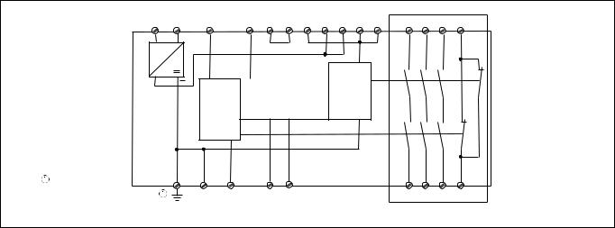
Fig. 1: Innenschaltbild/Internal Wiring Diagram/Schéma de principe
* Isolation zum nicht markierten Bereich und der Relaiskontakte zueinander: Basisisolierung (Überspannungskategorie III), sichere
Trennung (Überspannungskategorie II)
Betriebsarten
•Einkanaliger Betrieb: Eingangsbeschaltung nach VDE 0113 und EN 60204, keine
Redundanz im Eingangskreis, Erdschlüsse im Tasterkreis werden erkannt.
•Zweikanaliger Betrieb ohne Querschlusserkennung: Redundanter Eingangskreis, Kurzschlüsse und Erdschlüsse im Tasterkreis werden erkannt.
•Zweikanaliger Betrieb mit Querschlusserkennung: Redundanter Eingangskreis, Kurzschlüsse und Erdschlüsse im Tasterkreis und Querschlüsse zwischen den Tasterkontakten werden erkannt.
•Automatischer Start: Gerät ist aktiv, sobald der Eingangskreis geschlossen ist.
•Manueller Start: Gerät ist aktiv, wenn der Startkreis S33-S34 geschlossen wird.
•Manueller Start, überwacht: Gerät ist nur aktiv, wenn vor dem Schließen des Eingangskreises der Startkreis geöffnet wird und der Startkreis nach dem Schließen des Eingangskreises und nach Ablauf der Wartezeit (s. techn. Daten) geschlossen wird.
* Insulation between the non-marked area and the relay contacts: Basic insulation (overvoltage category III), safe separation
(overvoltage category II)
Operating Modes
•Single-channel operation: Input wiring according to VDE 0113 and EN 60204 and no redundancy in the input circuit. Earth faults are detected in the emergency stop circuit.
•Two-channel operation: no short circuit detection: Redundant input circuit. Earth faults and short circuits in the emergency stop circuit are detected.
•Dual-channel operation, with short circuit detection: Redundant input circuit. Earth faults in the emergency stop circuit and shorts across the Emergency Stop push button are also detected.
•Automatic reset: The unit is active as soon as the input circuit is closed.
•Manual reset: The unit is active when the reset circuit S33-S34 is closed.
•Monitored manual reset: Unit will only be active if the reset circuit is opened before the input circuit closes, and the reset circuit is closed after the input circuit has closed and the waiting period has elapsed
(see technical data).
* Isolation de la partie non sélectionnée par rapport aux contacts relais : isolation basique (catégorie de surtensions III), isolation galvanique (catégorie de surtensions II)
Modes de fonctionnement
•Commande par 1 canal : conforme aux prescriptions de la EN 60204, pas de redondance dans le circuit d’entrée. La mise à la terre du circuit d’entrée est détectée
•Commande par 2 canaux sans détection de court-circuit.: circuit d’entrée redondant. La mise à la terre et les défaillances des contacts sont détectées.
•Commande par 2 canaux avec détection de court-circuit.: circuit d’entrée redondant. La mise à la terre,les défaillance des contacts ainsi que les courts-cirucits entre les canaux sont détectés.
•Réarmement automatique : le relais est activé dès la fermeture des canaux d’entrée.
•Réarmement manuel : l'appareil est activé dès que le circuit S33-S34 est fermé.
•Réarmement manuel auto-contrôlé : L’appareil est uniquement actif lorsque le circuit de réarmement est ouvert avant fermeture des circuits d’entrées et que le circuit de réarmement est fermé après fermeture des circuits d’entrées et
écoulement du temps d’attente (cf. caractéristiques techniques).
- 2 -

• Kontaktvervielfachung und -verstärkung |
• Increase in the number of safety contacts |
durch Anschluss von externen Schützen |
available by connecting expander |
|
modules |
•Augmentation du nombre de contacts ou du pouvoir de coupure par l’utilisation de contacteurs externes.
Montage
Bauen Sie das Sicherheitsschaltgerät in einen Schaltschrank mit einer Schutzart von mindestens IP54 ein. Zur Befestigung auf einer Normschiene dient das Rastelement auf der Rückseite des Geräts.
Sichern Sie das Gerät bei Montage auf einer senkrechten Tragschiene (35 mm) durch ein
Halteelement wie z. B. Endhalter oder Endwinkel.
Installation
Install the safety relay in a panel (min. IP54).
There is a notch on the rear of the unit for DIN-Rail attachment.
If the unit is installed on a vertical mounting rail (35 mm), ensure it is secured using a fixing bracket such as end bracket.
Montage
Le relais doit être monté en armoire ayant un indice de protection mini IP54. Sa face arrière permet un montage sur rail DIN.
Immobilisez l'appareil monté sur un rail DIN vertical (35 mm) à l'aide d'un élément de maintien comme par ex. un support ou une
équerre terminale.
Inbetriebnahme
Beachten Sie bei der Inbetriebnahme:
•Gerät nur im spannungslosen Zustand verdrahten!
•Das Netzteil muss den Vorschriften für
Funktionskleinspannungen mit sicherer elektrischer Trennung (SELV, PELV) nach VDE 0100, Teil 410 entsprechen.
•Leitungsmaterial aus Kupferdraht mit einer Temperaturbeständigkeit von 60/75 °C verwenden.
•Sorgen Sie beim Anschluss von magnetisch wirkenden, auf Reedkontakten basierenden Näherungsschaltern dafür, dass der max. Einschaltspitzenstrom (am Eingangskreis) den Näherungsschalter nicht überlastet.
•Angaben im Kapitel „Technische Daten“ unbedingt einhalten.
•Bei Betrieb mit Wechselspannung ist eine lösbare Verbindung zwischen Gerät und Betriebserde erforderlich. Der Anschluss entfällt bei Gleichspannung.
•Auslieferungszustand: Brücke zwischen Y1-Y2
•Nur die Ausgangskontakte 13-14, 23-24,
33-34 sind Sicherheitskontakte. Ausgangskontakt 41-42 ist ein Hilfskontakt (z. B. für Anzeige).
•Vor die Ausgangskontakte eine Sicherung (s. techn. Daten) schalten, um das Verschweißen der Kontakte zu verhindern.
•Berechnung der max. Leitungslänge Imax
(Eingangskreis):
Imax = Rlmax
Rl / km
Rlmax = max. Gesamtleitungswiderstand
(Eingangskreis)
Rl /km = Leitungswiderstand/km
Wichtig für Querschlusserkennung: Da diese Funktion nicht einfehlersicher ist, wird sie von Pilz während der Endkontrolle geprüft.
Wenn Gefahr besteht, dass Sie die Leitungslängen überschreiten, empfehlen wir folgende Prüfung nach der Installation des Geräts:
1.Gerät betriebsbereit (Ausgangskontakte geschlossen)
2.Die Testklemmen S12, S22 zur Querschlussprüfung kurzschließen.
3.Die Sicherung im Gerät muss auslösen und die Ausgangskontakte öffnen. Leitungslängen in der Größenordnung der Maximallänge können das Auslösen der
Sicherung um bis zu 2 Minuten verzögern.
4.Sicherung wieder zurücksetzen: den Kurzschluss entfernen und die Versorgungsspannung für ca. 1 Minute abschalten.
Operation
For operation:
•Only wire the unit when voltage is not applied
•The power supply must comply with the regulations for extra low voltages with safe electrical separation (SELV, PELV) in accordance with VDE 0100, Part 410.
•Use copper wiring that will withstand 60/75 °C.
•When connecting magnetically operated, reed proximity switches, ensure that the max. peak inrush current (on the input circuit) does not overload the proximity switch.
•Important details in the section "Technical Data“ should be noted and adhered to.
•With AC operating voltage a detachable connection is required between unit and system earth. With DC operating voltage this connection is not necessary.
•Unit supplied with Y1-Y2 linked
•Only the output contacts 13-14, 23-24, 33-34 are safety contacts. Output contact 41-42 is an auxiliary contact (e.g. for signalling).
•To prevent contact welding, a fuse (see technical detail) must be connected before the output contacts.
•Calculate the max. Cable runs Imax (Input circuit):
Imax = |
Rlmax |
|
Rl / km |
||
|
Rlmax = Max. Total cable resistance (Input circuit)
Rl /km = Cable resistance/km
Important for short circuit detection:
As the function for detecting shorts across the inputs is not failsafe, it is tested by Pilz during the final control check. However, if there is a risk of exceeding the max. cable length, we recommend a test to be made after installing the unit as follows:
1.Unit ready for operation (output contacts closed)
2.Short circuit the test (connection) terminals S12, S22 for detecting shorts across the inputs
3.The unit‘s fuse must be triggered and the output contacts must open. Cable lengths in the scale of the maximum length can delay the fuse triggering for up to 2 minutes.
4.Reset the fuse: remove the short circuit and switch off the operating voltage for approx. 1 minute.
Mise en oeuvre
Remarques préliminaires :
•L'appareil doit être câblé hors tension !
•L'alimentation doit satisfaire aux prescriptions relatives aux tensions extra basses avec une isolation électrique de sécurité (SELV, PELV) selon VDE 0100, partie 410.
•Utiliser uniquement des fils de cablâge en cuivre 60/75 °C.
•Lors du raccordement de détecteurs de proximité magnétiques, basés sur des contacts Reed, veuillez vous assurer que le courant de crête max. à la mise sous tension (sur le circuit d'entrée) ne surcharge pas les détecteurs de proximité.
•Respecter les données indiquées dans le chap. „Caractéristiques techniques“.
•Pour les tensions d'alimentation alternatives
UB~, une liaison amovible entre le boîtier et la terre est exigée. Cette liaison n'est pas nécessaire pour les relais alimentés en 24VCC.
•Pontages présents à la livraison: Y1-Y2
•Seuls les contacts 13-14, 23-24, 33-34 sont des contacts de sécurité. Le contact 41-42 est un contact d’information
(ex. voyant)
•Raccordez une fusible (voir les caractéristiques techniques) avant les contacts de sortie afin d’éliminer tout risque de fusion.
•Calcular les longueurs de câblage max Imax (Circuits d’entrée):
Imax = Rlmax
Rl / km
Rlmax = résistivité de câblage totale max.
(Circuits d’entrée)
Rl /km = résistivité de câblage/km
Important pour la détection de courtcircuit
La fonction de détection de court-circuit est testé par Pilz lors du contrôle final.
Un test sur site en cas de risque de dépassement de la longueur de câblage est conseillé de la façon suivante :
1.Appareil en fonction (contacts de sortie fermés)
2.Court-circuiter les bornes S12-S22 pour générer un court-circuit
3.Le fusible interne du relais doit déclencher et les contacts de sortie doivent s‘ouvrir. Le temps de réponse du fuisible peut aller jusqu‘à 2 min. si les longueurs de câblage sont proches des valeurs maximales.
4.Réarmement du fusible : enlever le courtcircuit et couper l‘alimentation du relais pendant au moins 1 min.
- 3 -
Ablauf:
•Versorgungsspannung:
-Spannung an Klemmen A1 und A2 anlegen.
-nur bei AC: Betriebserdungsklemme mit Schutzleitersystem verbinden.
•Startkreis:
-Automatischer Start: S33-S34 und Y36Y37 brücken.
-Manueller Start mit Überwachung: Taster an S33-S34 anschließen (Y36Y37 offen).
-Manueller Start ohne Überwachung: Taster an S33-S34 anschließen, Y36Y37 brücken.
•Eingangskreis:
-Einkanalig: S12-S52 und S21-S22 brücken. Öffnerkontakt von Auslöseelement an S11 und S12 anschließen.
-Zweikanalig ohne Querschlusserkennung: S21-S22 brücken. Öffnerkontakt von Auslöseelement an S11-S12 und S11-S52 anschließen.
-Zweikanalig mit Querschlusserkennung: S11-S52 brücken. Öffnerkontakt von Auslöseelement an S11-S12 und S21-S22 anschließen.
•Rückführkreis: Y1-Y2 brücken oder in Reihe geschaltete Öffnerkontakte der externen Schütze anschließen.
Wenn die Versorgungsspannung eingeschaltet und die Startbedingung erfüllt ist, sind die Sicherheitskontakte geschlossen und der
Hilfskontakt 41-42 ist geöffnet. Die Statusanzeige "CH.1", "CH. 2" für Kanal 1 und Kanal 2 leuchtet. Das Gerät ist betriebsbereit.
Wenn der Eingangskreis geöffnet wird, öffnen die Sicherheitskontakte 13-14, 23-24, 33-34 und der Hilfskontakt 41-42 schließt. Die Statusanzeige "CH.1", "CH. 2" erlischt.
Wieder aktivieren
•Eingangskreis schließen.
•Bei manuellem Start ohne Überwachung Taster zwischen S33 und S34 betätigen.
•Bei manuellem Start mit Überwachung
Taster nach dem Schließen des Eingangskreises und nach Ablauf der
Wartezeit betätigen.
Die Statusanzeigen leuchten wieder, die Sicherheitskontakte sind geschlossen.
To operate:
•Supply voltage:
-Apply voltage to A1 and A2.
-AC only: Connect the operating earth terminal with the ground earth.
•Reset circuit:
-Automatic reset: Link S33-S34 and Y36-Y37.
-Manual reset with monitoring: Connect button to S33-S34 (Y36-Y37 open).
-Manual reset without monitoring: Connect button to S33-S34, Y36-Y37 linked.
•Input circuit:
-Single-channel: Link S12-S52 and S21S22. Connect N/C contact from safety switch (e.g. emergency stop) to S12 and S11.
-Dual-channel, without short circuit detection: Link S21-S22. Connect N/C contact from safety switch (e.g. emergency stop) to S11-S12 and S11S52
-Dual-channel, with short circuit detection: Link S11-S52. Connect N/C contact from safety switch to S11-S12 and S21-S22
•Feedback control loop: Link Y1-Y2 or
connect external relays/contactors in series
If the operating voltage is applied and all conditions met, the safety contacts are closed and the auxiliary contact (41-42) is open. The status indicators "CH.1"and
"CH.2" are illuminated. The unit is ready for operation.
If the input circuit is opened, the safety contacts 13-14, 23-24, 33-34 open and the auxiliary contact 41-42 closes. The status indicators go out.
Reactivation
•Close the input circuit.
•For manual reset without monitoring, press the button between S33-S34.
•For manual rest with monitoring, press the button after the input circuit has closed and the waiting time has elapsed.
The status indicators light up again, the safety contacts are closed.
Mise en oeuvre :
•Tension d’alimentation
-amener la tension d’alimentation sur A1 et A2.
-AC seulement: relier la borne terre
•Circuit de réarmement:
-réarmement automatique: pontage des bornes S33-S34 et Y36-Y37
-réarmement manuel auto-côntrolé: câblage d'un poussoir sur S33-S34
(Y36-Y37 ouvert)
-réarmement manuel sans côntrole: câblage d'un poussoir sur S33-S34, pontage des bornes Y36-Y37.
•Circuits d’entrée:
-Commande par 1 canal : câblage du contact à ouverture entre S11-S12, pontage entre S21-S52 et S21-S22
-Commande par 2 canaux sans détection des courts-circuits : câblage des contacts à ouverture entre S11-S12,
S11-S52, pontage entre S21-S22
-Commande par 2 canaux avec détection des courts-circuits : câblage des contacts à ouverture entre S11S12, S21-S22, pontage entre S11-S52
•Boucle de retour:
Ponter les bornes Y1-Y2 ou câbler en série les contacts repos des contacteurs externes
Dès que la tension d'alimentation et les conditions de réarmement sont présentes, les contacts de sécurité se ferment et le contact d’information 41-42 s’ouvre. Les LEDs "CH.1" et "CH.2" sont allumées.
L’appareil est prêt à fonctionner.
Si le circuit d’entrée est ouvert, les contacts de sécurité13-14, 23-24, 33-34 retombent et le contact d’information 41-42 se ferme. Les
LEDs s’éteignent.
Remise en route :
•fermer les circuits d’entrée
•Réarmement manuel : action sur le poussoir raccordé sur S33-S34
•Réarmement manuel auto-contrôlé : action sur BP après fermeture des circuits d’entrées et écoulement du temps d’attente.
Les affichages d'état s'allument à nouveau. Les contacts de sécurité sont fermées.
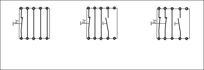
Anwendung
Fig. 2 bis Fig. 9 sind Anschlussbeispiele. Beachten Sie bei Fig. 2: Das Gerät startet bei Spannungsausfall und -wiederkehr automatisch. Verhindern Sie einen unerwarteten Wiederanlauf durch externe Schaltungsmaßnahmen.
Application
In Fig. 2...Fig. 9 are connection examples.
Please note for Fig. 2: the device starts automatically after loss of power. You should prevent an unintended start-up by using external circuitry measures.
Utilisation
Les figures 2 à 9 représentent les différents câblages possibles du PNOZ X4.
Dans le cas de la figure 2, l’appareil se réarme automatiquement après une coupure et une remise sous tension. Evitez tout risque de redémarrage par un câblage externe approprié.
S11 S12 S21 S33 Y36
S1
S12 S52 S22 S34 Y37
Fig. 2: Eingangskreis einkanalig, automat.
Start/Single-channel input circuit, automatic reset/Commande par 1 canal, validation automatique
S11 S12 S21 S33 Y36
S1
S3
S12 S52 S22 S34 Y37
Fig. 3: Eingangskreis einkanalig, überwachter Start/Single-channel input circuit, monitored reset/Commande par 1 canal, surveillance du poussoir de validation
S11 S11 S21 S33 Y36
S1
S3
S12 S52 S22 S34 Y37
Fig. 4: Eingangskreis zweikanalig, ohne
Querschlusserkennung, überwachter Start/
Two-channel input circuit, no short circuit detection, monitored reset/Commande par 2 canaux, sans détection de court-circuit, surveillance du poussoir de validation
- 4 -

S11 S21 S12 S33 Y36
S1
S3
S12 S22 S52 S34 Y37
Fig. 5: Schutztürsteuerung einkanalig, überwachter Start/Single-channel safety gate control, monitored reset/Surveillance de protecteur, commande par 1 canal, surveillance du poussoir de validation
|
S11 |
S11 |
S21 |
S33 Y36 |
|
BWS |
24 V DC |
|
|
|
|
|
|
|
S3 |
|
|
|
S12 |
S52 S22 |
S34 |
Y37 |
|
Fig. 8: Lichtschrankensteuerung, zweikanalig, Querschlusserkennung durch BWS, überwachter Start (nur bei
UB = 24 V DC)/Dual-channel light curtain control, short circuit detection via ESPE, monitored reset (only when
UB = 24 V DC)/Commande par 2 canaux par barrage immatériel, surveillance du poussoir de validation (uniquement pour UB = 24 V DC)
S11 S11 S33 Y36
S1
 S12 S3
 S21
S21
S2
S22 S52 S34 Y37
Fig. 6: Schutztürsteuerung zweikanalig, mit Querschlusserkennung, überwachter Start/ Two-channel safety gate control, with short circuit detection, monitored reset/
Surveillance de protecteur, commande par 2 canaux, avec détection de court-circuit, surveillance du poussoir de validation
Y1 |
13 |
|
|
K5
K5
K6
14 K6
K5 K6
Y2
Fig. 9: Anschlussbeispiel für externe Schütze, einkanalig, automatischer Start/ Connection example for external contactors/ relays, single-channel, automatic reset/ Branchement contacteurs externes, commande par 1 canal, validation automatique
S11 S21 S33 Y36
S12 |
S3 |
S11 |
|
S52 S22 S34 Y37
Fig. 7: Schutztürsteuerung zweikanalig, ohne Querschlusserkennung, nicht überwachter Start/Two channel safety gate control, no s/c detection, reset not monitored i.e. manual reset /Surveillance de protecteur, commande par 2 canaux, sans détection de court-circuit, validation non surveillée
S1/S2: Not-Halt- bzw. Schutztürschalter/ Emergency Stop Button, Safety Gate Limit Switch/Poussoir AU, détecteurs de position
S3: Starttaster/Reset button/Poussoir de réarmement
betätigtes Element/Switch activated/ élément actionné
Tür nicht geschlossen/Gate open/ porte ouverte
Tür geschlossen/Gate closed/porte fermée
Fehler - Störungen
•Erdschluss
-Betrieb mit Wechselspannung: Die Versorgungsspannung bricht zusammen und die Sicherheitskontakte werden geöffnet.
-Betrieb mit Gleichspannung: Die Versorgungsspannung bricht
zusammen und die Sicherheitskontakte werden über eine elektronische Sicherung geöffnet. Nach Wegfall der Störungsursache und Abschalten der
Versorgungsspannung für ca. 1 Minute ist das Gerät wieder betriebsbereit.
•Fehlfunktionen der Kontakte: Bei verschweißten Kontakten ist nach Öffnen des Eingangskreises keine neue Aktivierung möglich.
•LED "Power" leuchtet nicht: Kurzschluss oder Versorgungsspannung fehlt
Faults
•Earth fault
-AC operation: The supply voltage fails and the safety contacts are opened.
-DC operation: Supply voltage fails and the safety contacts are opened via an electronic fuse. Once the cause of the fault has been removed and operating voltage is switched off, the unit will be ready for operation after approximately 1 minute.
•Contact failure: In the case of welded contacts, no further activation is possible following an opening of the input circuit.
•LED "Power" is not illuminated if shortcircuit or the supply voltage is lost.
Erreurs - Défaillances
•Défaut de masse
-AC: la tension d’alimentation s’effondre et les contacts de sortie s’ouvrent.
-DC: La tension d’alimentation chute et les contacts de sécurité sont ouverts par un fusible électronique. Une fois la cause du défaut éliminée et la tension d’alimentation coupée, l’appareil est à nouveau prêt à fonctionner après environ 1 minute.
•Défaut de fonctionnement des contacts de sortie: en cas de soudage d’un contact lors de l’ouverture du circuit d’entrée, un nouvel réarmement est impossible.
•LED "Power" éteinte: tension d'alimentation non présente ou courtcircuit interne.
- 5 -

Technische Daten |
Technical Data |
Caractéristiques techniques |
|
|
|
|
|
Elektrische Daten |
Electrical data |
Données électriques |
|
Versorgungsspannung UB |
Supply voltage UB |
Tension d’alimentation UB |
AC: 24, 110, 115, 120, |
|
|
|
230, 240 V |
DC: 24 V
Spannungstoleranz |
Voltage tolerance |
Plage de la tension d’alimentationn |
Leistungsaufnahme bei UB |
Power consumption at UB |
Consomation pour UB |
|
|
|
Frequenzbereich |
Frequency Range |
Fréquence |
|
|
|
Restwelligkeit |
Residual ripple |
Ondulation résiduelle |
|
|
|
-15 ... +10 %
UB DC: 2,5 W UB AC: 5,0 VA
AC: 50 ... 60 Hz
DC: 160 %
Spannung und Strom an |
Voltage and current at |
Tension et courant au |
|
Eingangskreis |
Input circuit |
circuit d’entrée |
24 V DC: 40 mA |
Startkreis |
Reset circuit |
circuits de réarmement |
UB AC: 24 V DC/90,0 mA |
|
|
|
UB DC: 24 V DC/70,0 mA |
Rückführkreis |
Feedback circuit |
boucle de retour |
UB AC: 24 V DC/90,0 mA |
|
|
|
UB DC: 24 V DC/70,0 mA |
Anzahl der Ausgangskontakte |
Number of output contacts |
Nombre de contacts de sortie |
||
Sicherheitskontakte (S) |
|
Safety contacts (N/O) |
Contacts de sécurité (F) |
|
Hilfskontakte (Ö) |
|
|
Auxiliary contacts (N/C) |
Contact d’info (O) |
Gebrauchskategorie |
nach |
Utilisation category in accordance |
Catégorie d’utilisation selon |
|
EN 60947-4-1 |
|
|
with EN 60947-4-1 |
EN 60947-4-1 |
EN 60947-5-1 |
|
|
EN 60947-5-1 |
EN 60947-5-1 |
(DC13: 6 Schaltspiele/Min.) |
(DC13: 6 cycles/min) |
(DC13 : 6 manœuvres/min) |
||
Kontaktmaterial |
|
|
Contact material |
Matériau des contacts |
|
|
|
|
|
Kontaktabsicherung |
extern nach |
External contact fuse protection in |
Protection des contacts externe |
|
EN 60947-5-1 (IK = 1 kA) |
|
accordance with EN 60947-5-1 |
selon EN 60947-5-1 (IK = 1 kA) |
|
Schmelzsicherung |
flink |
|
(IK = 1 kA) |
Fusible rapide |
|
Blow-out fusequick |
|||
Schmelzsicherung |
träge |
|
Blow-out fuseslow |
Fusible normal |
Sicherungsautomat |
|
Safety cut out |
Disjoncteur |
|
Charakteristik |
|
|
Characteristic |
Caractéristique |
Max. Gesamtleitungswiderstand RlmaxMax. overall cable resistance Rlmax |
Résistance de câblage totale max. |
|||
Eingangskreise |
|
|
input circuits |
Rlmax circuits d’entrée |
einkanalig DC |
|
|
Single-channel DC |
Commande par 1 canal DC |
einkanalig AC |
|
|
Single-channel AC |
Commande par 1 canal AC |
zweikanalig ohne |
|
|
Dual-channel without detection of |
Commande par 2 canaux sans |
Querschlusserkennung |
DC |
shorts across contacts DC |
détection des court-circuits DC |
|
zweikanalig ohne |
|
|
Dual-channel without detection of |
Commande par 2 canaux sans |
Querschlusserkennung |
AC |
shorts across contacts AC |
détection des court-circuits AC |
|
zweikanalig mit |
|
|
Dual-channel with detection of |
Commande par 2 canaux avec |
Querschlusserkennung |
DC |
shorts across contacts DC |
détection des court-circuits DC |
|
zweikanalig mit |
|
|
Dual-channel with detection of |
Commande par 2 canaux avec |
Querschlusserkennung |
AC |
shorts across contacts AC |
détection des court-circuits AC |
|
3
1
AC1: 240 V/0,01 ... 8 A/ 2000 VA
DC1: 24 V/0,01 ... 8 A/ 200 W
AC15: 230 V/5 A;
DC13: 24 V/7 A
AgSnO2+ 0,2 µm Au
10 A
6 A
24 V AC/DC: 6 A B/C
20 Ohm
150 Ohm
20 Ohm
150 Ohm
15 Ohm
100 Ohm
Min. Eingangswiderstand im |
Min. input resistance when |
Résistance d'entrée min. au moment |
Einschaltmoment |
switching on |
de la mise en marche |
Sicherheitstechnische Kenn- |
Safety-related characteristics of |
Caractéristiques techniques de |
daten der Sicherheitsausgänge |
the safety outputs |
sécurité des sorties de sécurité |
PL nach EN ISO 13849-1: 2006 |
PL in accordance with |
PL selon EN ISO 13849-1: 2006 |
|
EN ISO 13849-1: 2006 |
|
Kategorie nach EN 954-1 |
Category in accordance with |
Catégorie selon EN 954-1 |
|
EN 954-1 |
|
SIL CL nach EN IEC 62061 |
SIL CL in accordance with |
SIL CL selon EN IEC 62061 |
|
EN IEC 62061 |
|
PFH nach EN IEC 62061 |
PFH in accordance with |
PFH selon EN IEC 62061 |
|
EN IEC 62061 |
|
SIL nach IEC 61511 |
SIL in accordance with IEC 61511 |
SIL selon IEC 61511 |
PFD nach IEC 61511 |
PFD in accordance with IEC 61511 |
PFD selon IEC 61511 |
TM [Jahr] nach EN ISO 13849-1: |
TM [year] in accordance with |
TM [année] selon EN ISO 13849-1: |
2006 |
EN ISO 13849-1: 2006 |
2006 |
Zeiten |
Times |
Temporisations |
165 Ohm
PL e (Cat. 4)
Cat. 4
SIL CL 3
2,31E-09
SIL 3
2,03E-06
20
Einschaltverzögerung |
Switch-on delay |
Temporisation |
d’enclenchement |
|
automatischer Start |
Automatic reset |
Réarmement automatique |
||
UB AC: |
UB AC: |
UB AC: |
|
typ. 210 ms, max. 350 ms |
UB DC: |
UB DC: |
UB DC: |
|
typ. 270 ms, max. 600 ms |
automatischer Start nach Netz-Ein |
Automatic reset after Power-ON |
Réarmement automatique après |
||
|
|
mise sous tension |
||
UB AC: |
UB AC: |
UB AC: |
|
typ. 240 ms, max. 390 ms |
UB DC: |
UB DC: |
UB DC: |
|
typ. 270 ms, max. 600 ms |
manueller Start |
Manual Reset |
Réarmement manuel |
||
UB AC: |
UB AC: |
UB AC: |
|
typ. 55 ms, max. 350 ms |
UB DC: |
UB DC: |
UB DC: |
|
typ. 70 ms, max. 600 ms |
überwachter Start |
Monitored reset |
Réarmement |
auto-contrôlé |
|
UB AC: |
UB AC: |
UB AC: |
|
typ. 30 ms, max. 50 ms |
UB DC: |
UB DC: |
UB DC: |
|
typ. 40 ms, max. 70 ms |
|
- 6 - |
|
|
|
 Loading...