


22172-3FR-01 PSEN cs3.1n
4 D Betriebsanleitung
4 GB Operating instructions
4 F Manuel d'utilisation
Sicherheitsschalter PSEN cs3.1n |
|
|
Safety switch PSEN cs3.1n |
Capteur de sécurité PSEN cs3.1n |
|||||||||
Der Sicherheitsschalter erfüllt die Anforderun- |
The safety switch meets the requirements in |
Le capteur de sécurité satisfait aux exigences |
|||||||||||
gen nach: |
|
|
|
|
accordance with: |
des normes : |
|||||||
` EN 60204-1 |
|
|
` EN 60204-1 |
` EN 60204-1 |
|||||||||
` EN 60947-5-3: PDF-M zusammen mit dem |
` EN 60947-5-3: PDF-M in conjunction with |
` EN 60947-5-3 : PDF-M avec l'actionneur |
|||||||||||
Betätiger (siehe Technische Daten). |
|
|
the actuator (see Technical Details). |
(voir les caractéristiques techniques). |
|||||||||
` EN 62061: SIL CL 3 |
|
|
` EN 62061: SIL CL 3 |
` EN 62061 : SIL CL 3 |
|||||||||
` EN ISO 13849-1. PL e und Kat. 4 |
|
|
` EN ISO 13849-1. PL e and Cat. 4 |
` EN ISO 13849-1. PL e et cat. 4 |
|||||||||
` Der Sicherheitsschalter darf nur mit dem zu- ` The safety switch may only be used with the |
` Le capteur de sécurité doit être utilisé uni- |
||||||||||||
gehörigen Betätiger verwendet werden (sie- |
corresponding actuator (see Technical De- |
quement avec l'actionneur correspondant |
|||||||||||
he Technische Daten). |
|
|
tails). |
|
|
|
|
(voir les caractéristiques techniques). |
|||||
|
|
vorläufig |
|||||||||||
` Die Sicherheitsausgänge müssen 2-kanalig |
` The safety outputs must use 2-channel |
` Les sorties de sécurité doivent être traitées |
|||||||||||
weiterverarbeitet werden. |
|
|
processing. |
par 2 canaux. |
|||||||||
Zu Ihrer Sicherheit |
|
|
For your safety |
Pour votre sécurité |
|||||||||
` Installieren und nehmen Sie das Gerät nur |
` Only install and commission the unit if you |
` Vous n'installerez l'appareil et ne le mettrez |
|||||||||||
dann in Betrieb, wenn Sie diese Betriebsan- |
have read and understood these operating |
en service qu'après avoir lu et compris le |
|||||||||||
leitung gelesen und verstanden haben und |
instructions and are familiar with the applica- |
présent manuel d'utilisation et vous être fa- |
|||||||||||
Sie mit den geltenden Vorschriften über Ar- |
ble regulations for health and safety at work |
miliarisé avec les prescriptions en vigueur |
|||||||||||
beitssicherheit und Unfallverhütung vertraut |
and accident prevention. |
sur la sécurité du travail et la prévention des |
|||||||||||
sind. |
|
|
|
|
Ensure VDE and local regulations are met, |
accidents. |
|||||||
Beachten Sie die VDEsowie die örtlichen |
especially those relating to safety. |
Respectez les normes locales ou VDE, parti- |
|||||||||||
Vorschriften, insbesondere hinsichtlich |
` Any guarantee is rendered invalid if the hous- |
culièrement en ce qui concerne la sécurité. |
|||||||||||
Schutzmaßnahmen |
|
|
ing is opened or unauthorised modifications |
` L'ouverture de l'appareil ou sa modification |
|||||||||
` Durch Öffnen des Gehäuses oder eigen- |
are carried out. |
annule automatiquement la garantie. |
|||||||||||
mächtige Umbauten erlischt jegliche Ge- |
` Do not remove the protective cap until you |
` Veuillez retirer le cache de protection avant |
|||||||||||
währleistung. |
|
|
are just about to connect the unit. |
de raccorder l'appareil. |
|||||||||
` Entfernen Sie die Schutzkappe erst unmittel- |
|
|
|
|
|
|
|
|
|||||
bar vor Anschluss des Geräts. |
|
|
|
|
|
|
|
|
|
|
|||
Gerätemerkmale |
|
|
Unit features |
Caractéristiques de l'appareil |
|||||||||
` Transpondertechnik |
|
|
` Transponder technology |
` Technique à transpondeur |
|||||||||
` Zweikanaliger Betrieb |
|
|
` Dual-channel operation |
` Commande par 2 canaux |
|||||||||
` 2 Sicherheitsausgänge |
|
|
` 2 safety outputs |
` 2 sorties de sécurité |
|||||||||
` LED-Anzeige für: |
|
|
` LED for: |
` LEDs de visualisation : |
|||||||||
– |
Zustand Betätiger |
|
|
– |
Status of the actuator |
– |
état de l'actionneur |
||||||
– |
Versorgungsspannung/Fehler |
|
|
– |
Supply voltage/fault |
– |
tension d'alimentation / défauts |
||||||
` 1 Betätigungsrichtung |
|
|
` 1 direction of actuation |
` 1 sens de manœuvre |
|||||||||
` 5-poliger M12 Stiftstecker |
|
|
` 5 pin M12 male connector |
` Connecteur mâle à 5 broches M12 |
|||||||||
` Codierung: codiert |
|
|
` Coding: coded |
` Code : codé |
|||||||||
Blockschaltbild |
|
|
Block diagram |
Schéma de principe |
|||||||||
|
|
|
A1 |
A2 |
|
|
|
|
|
|
|
|
|
|
|
|
|
|
|
|
|
|
|
|
|
|
|
|
|
|
|
|
|
|
|
|
|
|
|
|
|
|
|
|
Power |
|
|
|
|
|
Receiver |
|
|
Actuator |
|
|
|
|
|
|
|
|
|
|
|
||||
|
|
|
|
|
|
|
|
|
|
|
|
||
|
|
|
|
|
|
|
|
|
|
|
|
|
|
|
|
|
|
|
|
|
|
|
|
|
|
|
|
|
|
|
|
|
|
|
12 |
22 |
|
|
|
|
|
|
|
|
|
|
|
|
|
|
|
|
|
||
|
|
|
|
|
|
|
|
- 1 - |
|
|
|
||

Funktionsbeschreibung |
Function description |
Die Sicherheitsausgänge 12 und 22 leiten, |
Safety outputs 12 and 22 conduct when |
wenn |
` the actuator is in the response range |
` der Betätiger sich im Ansprechbereich befinSafety outputs 12 and 22 are disabled when
det |
` the actuator is outside the response range |
Die Sicherheitsausgänge 12 und 22 sperren, |
|
wenn |
|
`der Betätiger sich außerhalb des Ansprechbereichs befindet
Description du fonctionnement
Les sorties de sécurité 12 et 22 sont sous tension si
` l'actionneur se trouve dans la zone de détection
Les sorties de sécurité 12 et 22 sont verrouillées si :
`l'actionneur se trouve à l'extérieur de la zone de détection ou si
Schaltabstände |
Operating distances |
|
Distances de commutation |
|||
1 |
2 |
3 |
|
|
|
|
|
y |
|
|
|
|
|
|
Ein/On/Marche |
|
|
|
|
|
|
Aus/Off/Arrêt |
|
|
|
|
|
|
|
somin |
sao so |
sr |
sar |
(mm) x |
Legende |
vorläufig |
|||||||
|
|
Key |
|
Légende |
|
|||
` c: Seitenversatz |
|
` c: Lateral offset |
|
` c: décalage latéral |
|
|||
` d: Höhenversatz |
|
` d: Vertical offset |
|
` d: décalage en hauteur |
||||
` e: Schaltzustände (y-Achse) in Abhängigkeit |
` e: Switch statuses (y-axis) dependent on |
` e: états de commutation (axe y) en fonction |
||||||
der Schaltabstände (x-Achse) |
operating distances (x-axis) |
|
des distances de commutation (axe x) |
|||||
` Sao: Gesicherter Schaltabstand: 8,0 mm |
` Sao: Assured operating distance: 8,0 mm |
` Sao : distance de commutation de sécurité : |
||||||
` So: Typischer Schaltabstand: 11,0 mm |
` So: Typical operating distance: 11,0 mm |
|
8,0 mm |
|
||||
` Sr: Typischer Ausschaltabstand: 14,0 mm |
` Sr: Typical release distance: 14,0 mm |
` So : distance de commutation caractéristi- |
||||||
` Sar: Gesicherter Ausschaltabstand: 20 mm |
` Sar: Assured release distance: 20 mm |
|
que : 11,0 mm |
|
||||
|
|
|
|
|
` Sr : distance de déclenchement caractéristi- |
|||
|
|
|
|
|
|
que : 14,0 mm |
|
|
|
|
|
|
|
` Sar : distance de déclenchement de sécurité |
|||
|
|
|
|
|
|
: 20 mm |
|
|
Seitenund Höhenversatz |
|
Lateral and vertical offset |
Décalage latéral et en hauteur |
|||||
|
|
4 |
4 |
|
0 |
5 |
10 |
|
|
3 |
|
|
|
|
|
-10 |
|
|
|
|
|
|
|
|
-8 |
4 |
|
2 |
-10 -8 -6 -4 0 4 6 8 10 mm |
|
|
|
-6 |
|
|
|
10 |
|
10 |
5 |
|
|
-4 |
|
|
5 |
|
5 |
|
|
|
0 |
|
|
0 |
|
0 |
|
|
|
4 |
|
|
|
|
|
|
|
|
6 |
4 |
|
|
|
|
|
|
|
8 |
|
|
|
|
|
|
|
|
|
|
|
1 |
|
|
6 |
|
|
10 |
|
|
|
|
0 |
5 |
10 mm |
|
||
|
|
|
|
|
|
|||
Legende |
|
|
Key |
|
Légende |
|
||
` c: Hysterese |
|
|
` c: Hysteresis |
|
` c: Hystérésis |
|
||
` d: Typischer Schaltabstand SO |
` d: Typical operating distance SO |
` d: Distance approximative de commutation |
||||||
` e: Typischer Ausschaltabstand Sr |
` e: Typical release distance Sr |
|
SO |
|
|
|||
` f: Versatz in mm |
|
` f: Offset in mm |
|
` e: Distance approximative de déclenche- |
||||
` g: Schaltabstand in mm |
|
` g: Operating distance in mm |
|
ment Sr |
|
|||
` h: Ansprechbereich |
|
` h: Response range |
|
` f: Décalage en mm |
|
|||
` g: Distance de commutation en mm ` h: Zone de déclenchement
- 2 -
Verdrahtung
Beachten Sie:
`Angaben im Abschnitt „Technische Daten“ unbedingt einhalten.
`Berechnung der max. Leitungslänge Imax im Eingangskreis:
Imax = Rlmax
Rl / km
Rlmax = max. Gesamtleitungswiderstand (s. techn. Daten)
Rl / km = Leitungswiderstand/km
Wiring
Please note:
`Information given in the “Technical details” must be followed.
`Calculation of the max. cable length lmax in the input circuit:
Imax = Rlmax
Rl / km
Rlmax = max. overall cable resistance (see Technical details)
Rl / km = cable resistance/km
Raccordement
Important :
`Respectez impérativement les données indiquées dans la partie "Caractéristiques techniques".
`Calcul de la longueur de câble max. Imax sur le circuit d'entrée :
Imax = Rlmax
Rl / km
Rlmax = résistance max. de l'ensemble du câblage (voir les caractéristiques techniques)
Rl / km = résistance du câblage/km
Anschlüsse |
|
Connections |
|
Raccordements |
||
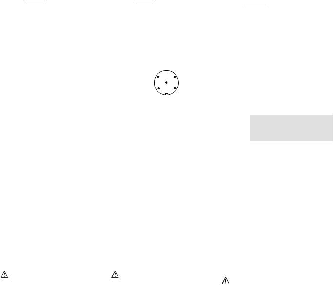
Stiftstecker 5-pol. M12 (male) |
|
Connector 5 pin M12 (male) |
Connecteur mâle M12 à 5 broches |
|||
|
|
|
4 |
3 |
|
|
|
|
|
|
5 |
|
|
|
|
|
1 |
2 |
|
|
|
|
|||||
|
vorläufig |
|||||
Anschlussbelegung Stecker und Kabel |
Pin assignment, connector and cable |
Affectation des bornes - connecteur et câble |
||||
Anschlussbezeichnung im |
Funktion/ |
|
PIN/ |
|
Adernfarbe (Pilz Kabel)/ |
|
Blockschaltbild/ |
Function/ |
|
Broche |
|
Cable colour (Cable Pilz)/ |
|
Terminal designation/ |
Foncion |
|
|
|
Couleur du fil (fil de Pilz) |
|
Désignation des bornes |
|
|
|
|
|
|
A1 |
|
+24 UB |
|
1 |
|
braun/brown/marron |
12 |
|
Ausgang Kanal 1/ |
2 |
|
weiß/white/blanc |
|
|
|
Output, channel 1/ |
|
|
|
|
|
|
Canal de sortie 1 |
|
|
|
|
22 |
|
Ausgang Kanal 2/ |
4 |
|
schwarz/black/noir |
|
|
|
Output, channel 2/ |
|
|
|
|
|
|
Canal de sortie 2 |
|
|
|
|
A2 |
|
0 V UB |
|
3 |
|
blau/blue/bleu |
- |
|
nicht anschließen/ |
5 |
|
grau/grey/gris |
|
|
|
do not connect/ |
|
|
|
|
|
|
pas raccordé |
|
|
|
|
Anschluss an Auswertegeräte |
|
Connection to evaluation devices |
Raccordement aux appareils de contrôle |
|||
Bitte beachten Sie: |
|
Please note: |
|
Tenez compte de ce qui suit : |
||
` das Netzteil muss den Vorschriften für Klein- ` The power supply must meet the regulations |
` Cette alimentation doit être conforme aux |
|||||
spannungen mit sicherer Trennung (SELV, |
for extra low voltages with safe separation |
prescriptions relatives aux basses tensions à |
||||
PELV) entsprechen. |
|
(SELV, PELV). |
|
séparation galvanique (SELV, PELV). |
||
` die Einund Ausgänge des Sicherheitsschal- ` the inputs and outputs of the safety switch |
` Les entrées et les sorties du capteur de sé- |
|||||
ters müssen eine sichere Trennung zu Span- |
must have a safe separation to voltages over |
curité doivent posséder une séparation gal- |
||||
nungen über 60 V AC besitzen. |
|
60 V AC. |
|
vanique pour les tensions supérieures à |
||
|
ACHTUNG! |
|
CAUTION! |
|
60 V AC. |
|
|
Die Sicherheitsausgänge müssen 2-ka- |
The safety outputs must use 2-channel |
ATTENTION ! |
|||
|
nalig weiterverarbeitet werden. |
processing. |
|
Les sorties de sécurité doivent être trai- |
||
|
|
|
|
|
tées par 2 canaux. |
|
- 3 -
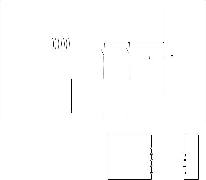
` Anschaltung |
` Interface |
` Raccordement |
24 V 0 V
|
|
|
|
|
|
|
|
|
|
|
|
|
|
|
Betätiger/ |
|
|
|
|
Empfänger/ |
|
|
|
|
|
||
|
Actuator/ |
|
|
|
|
Reciever/ |
|
|
|
|
|
|
|
|
Actioneur |
|
|
|
|
Recépteur |
|
|
|
|
|
|
|
|
|
|
|
|
|
|
|
|
A1 |
|
|
|
|
|
|
|
|
|
|
|
|
|
A2 |
|
|
|
|
|
|
|
|
|
|
|
|
|
|
|
|
|
|
|
|
|
12 |
22 |
|
|
|
|
|
|
|
||
|
|
|
|
|
I1 (FS) |
I2 (FS) |
|
|
|
|
|
|
|
|
|
|
|
|
Auswertegerät/ |
|
|
A1 |
|
|
|
|
|
|
|
|
|
|
Evaluation device/ |
|
|
|
|
|
|
||
vorläufig |
|
|
|
|
|
||||||||
|
|
|
|
|
Appareil de surveillance |
|
|
|
|
|
|
|
|
|
|
|
|
|
|
|
|
|
A2 |
|
|
|
|
|
|
|
|
FS: Fail-safe |
|
|
|
|
|
|
|
|
|
|
|
|
|
ST: Standard |
|
|
|
|
|
|
|
|
|
` Anschluss an PDP67 |
` Connection to PDP67 |
` Raccordement à PDP67 |
|
|
|
||||||||
|
|
|
|
|
|
PDP67 |
|
|
PSENcode |
||||
|
|
|
|
|
|
Test Pulse X / 24 V DC1 |
|
|
|
|
1 A1 |
||
|
PDP67 F 8DI ION |
|
|
|
0 V |
3 |
|
|
|
|
3 A2 |
||
|
|
|
|
|
|
Input X |
2 |
|
|
|
|
2 |
12 |
|
|
|
|
|
|
Input X + 1 |
4 |
|
|
|
|
4 |
22 |
|
|
|
|
|
Test Pulse X + 1 / 24 V DC5 |
|
|
|
|
5 |
n.c. |
||
- 4 -
 Loading...