


19238-6NL-04
PNOZ X2, PNOZ X2.1, PNOZ X2.2
4 D |
Betriebsanleitung |
4 E |
Instrucciones de uso |
|
4 GB |
Operating instructions |
4 I |
Istruzioni per l`uso |
|
4 F |
Manuel d'utilisation |
4 NL |
Gebruiksaanwijzing |
|
|
|
|
|
|
|
|
|
|
|
 Sicherheitsbestimmungen
•Das Gerät darf nur von Personen installiert und in Betrieb genommen werden, die mit dieser Betriebsanleitung und den geltenden Vorschriften über
Arbeitssicherheit und Unfallverhütung vertraut sind. Beachten Sie die VDEsowie die örtlichen Vorschriften, insbesondere hinsichtlich Schutzmaßnahmen.
•Beim Transport, der Lagerung und im
Betrieb die Bedingungen nach EN 60068- 2-6 einhalten (s. technische Daten).
•Durch Öffnen des Gehäuses oder eigenmächtige Umbauten erlischt jegliche Gewährleistung.
•Montieren Sie das Gerät in einen Schaltschrank; Staub und Feuchtigkeit können sonst zu Beeinträchtigungen der Funktionen führen.
•Sorgen Sie an allen Ausgangskontakten bei kapazitiven und induktiven Lasten für eine ausreichende Schutzbeschaltung.
 Safety Regulations
•The unit may only be installed and operated by personnel who are familiar with both these instructions and the current regulations for safety at work and accident prevention. Follow VDE and local regulations especially as regards preventative measures.
•Transport, storage and operating conditions should all conform to EN 60068-2-6.
•Any guarantee is void following opening of the housing or unauthorised modifications.
•The unit should be panel mounted, otherwise dampness or dust could lead to function impairment.
•Adequate protection must be provided on all output contacts especially with capacitive and inductive loads.
 Conseils préliminaires
•La mise en oeuvre de l’appareil doit être effectuée par une personne spécialisée en installations électriques, en tenant compte des prescriptions des différentes normes applicables (NF, EN, VDE...) notamment au niveau des risques encourus en cas de défaillance de l’équipement électrique.
•Respecter les exigences de la norme EN 60068-2-6 lors du transport, du stockage et de l'utilisation de l'appareil.
•L’ouverture de l’appareil ou sa modification annule automatiquement la garantie.
•L’appareil doit être monté dans une armoire; l’humidité et la poussière pouvant entraîner des aléas de fonctionnement.
•Vérifiez que le pouvoir de coupure des contacts de sortie est suffisant en cas de circuits capacitifs ou inductifs.
Bestimmungsgemäße Verwendung
Das Sicherheitsschaltgerät dient dem sicherheitsgerichteten Unterbrechen eines Sicherheitsstromkreises.
Das Sicherheitsschaltgerät erfüllt Forderungen der EN 60947-5-1, EN 60204-1 und
VDE 0113-1 und darf eingesetzt werden in Anwendungen mit
•Not-Halt-Tastern
•Schutztüren
Das Gerät ist nicht für die Absicherung von berührungslosen Verdeckungen geeignet, da kein dynamischer Start möglich ist.
Authorised Applications
The safety relay provides a safety-related interruption of a safety circuit.
The safety relay meets the requirements of
EN 60947-5-1, EN 60204-1 and VDE 0113- 1 and may be used in applications with
•E-STOP pushbuttons
•Safety gates
The device is not suitable for non-contact barriers (e.g. light curtains) because a dynamic start is not possible.
Domaines d’utilisation
Le bloc logique de sécurité sert à interrompre en toute sécurité un circuit de sécurité.
Le bloc logique de sécurité satisfait aux exigences des normes EN 60947-5-1,
EN 60204-1 et VDE 0113-1 et peut être utilisé dans des applications avec des
•poussoirs d’arrêt d’urgence
•protecteurs mobiles
L'appareil n'est pas adapté à la surveillance de barrières immatérielles car une validation dynamique n'est pas possible (surveillance du circuit de réarmement).
Gerätebeschreibung
Das Sicherheitsschaltgerät PNOZ X2/X2.1/
X2.2 ist in einem S-95-Gehäuse untergebracht. Es kann mit 24 V Wechselspannung oder mit 24 V Gleichspannung betrieben werden.
Merkmale:
•Relaisausgänge: 2 Sicherheitskontakte
(Schließer), zwangsgeführt
•Anschlussmöglichkeit für Not-Halt- Taster, Schutztürgrenztaster und Starttaster
•PNOZ X2: überwachter Starttaster
•PNOZ X2.1: automatischer Start möglich
•PNOZ X2.2: wie PNOZ X2, zusätzlich können mehrere Geräte parallel mit einem Starttaster gestartet werden
•Statusanzeige
•Überwachung externer Schütze möglich
•keine galvanische Trennung
Das Schaltgerät erfüllt folgende Sicherheitsanforderungen:
•Schaltung ist redundant mit Selbstüberwachung aufgebaut
Description
The Safety Relay PNOZ X2/X2.1/X2.2 is enclosed in a S-95 housing. Every unit can be operated with 24 V AC or 24 V DC.
Features:
•Relay outputs: 2 safety contacts (N/O), positive-guided.
•Connections for Emergency Stop Button,
Safety Gate Limit Switch and Reset button.
•PNOZ X2: monitored manual reset
•PNOZ X2.1: automatic reset possible
•PNOZ X2.2: As PNOZ X2. In addition, several units may be started in parallel using one start button.
•Status Indicators.
•Feedback Control Loop for monitoring of external contactors/relays possible
•no galvanic seperation
The relay complies with the following safety requirements:
•The circuit is redundant with built-in selfmonitoring
Description de l’appareil
Inséré dans un boîtier S 95, le bloc logique de sécurité PNOZ X2/X2.1/X2.2 peut être alimenté en 24 V AC ou en 24 V DC. Particularités :
•Sorties disponibles : 2 contacts à fermeture de sécurité
•Bornes de raccordement pour poussoirs
AU, détecteurs de position et poussoir de validation
•PNOZ X2: surveillance du circuit de validation
•PNOZ X2.1: réarmement automatique possible
•PNOZ X2.2: comme PNOZ X2, mais permet le réarmement de plusieurs appareils en parallèle avec un seul poussoir de réarmement.
•LEDs de visualisation
•Auto-contrôle des contacteurs externes possible
•pas d'isolation galvanique
Le relais PNOZ X2/X2.1/X2.2 répond aux exigences suivantes :
•conception redondante avec autosurveillance
- 1 -
•Sicherheitseinrichtung bleibt auch bei Ausfall eines Bauteils wirksam.
•Bei jedem Ein-Aus-Zyklus der Maschine wird automatisch überprüft, ob die Relais der Sicherheitseinrichtung richtig öffnen und schließen.
•The safety function remains effective in the case of a component failure.
•The correct opening and closing of the safety function relays is tested automatically in each on-off cycle.
•sécurité garantie même en cas de défaillance d’un composant
•test cyclique (ouverture/fermeture des relais internes) à chaque cycle Marche/
Arrêt de la machine
Funktionsbeschreibung
Das Schaltgerät PNOZ X2/X2.1/X2.2 dient dem sicherheitsgerichteten Unterbrechen eines Sicherheitsstromkreises. Nach Anlegen der Versorgungsspannung leuchtet die LED "POWER". Das Gerät ist betriebsbereit, wenn der Startkreis S33-S34 geschlossen ist.
•Eingangskreis geschlossen (z. B. Not- Halt-Taster nicht betätigt):
Relais K1 und K2 gehen in Wirkstellung und halten sich selbst. Die Statusanzeigen
"CH.1" und "CH.2" leuchten. Die Sicherheitskontakte 13-14/23-24 sind geschlossen.
•Eingangskreis wird geöffnet (z. B. Not- Halt-Taster betätigt):
Relais K1 und K2 fallen in die Ruhestellung zurück. Die Statusanzeige für "CH.1" und "CH.2" erlischt. Die Sicherheitskontakte 13-14/23-24 werden redundant geöffnet.
Function Description
The relay PNOZ X2/X2.1/X2.2 provides a safety-oriented interruption of a safety circuit.
When the operating voltage is supplied the LED "POWER" is illuminated. The unit is ready for operation, when the reset circuit S33-S34 is closed.
•Input Circuit closed (e.g. the Emergency
Stop button is not pressed):
Relays K1and K2 energise and retain themselves. The status indicators for
"CH.1" and "CH.2" illuminate. The safety contacts (13-14/23-24) are closed.
•Input Circuit is opened (e.g. Emergency Stop is pressed)
Relays K1 and K2 de-energise. The status indicators for "CH.1" and "CH.2" go out. The safety contacts (13-14/23-24) will be opened (redundant).
Description du fonctionnement
Le relais PNOZ X2/X2.1/X2.2 assure de façon sure, l’ouverture d’un circuit de sécurité. A la mise sous tension du relais (A1-A2), la LED "POWER" s'allume. Le relais est activé si le circuit de réarmement S33-S34 est fermé.
•Circuits d'entrée fermés (poussoir AU non actionné) :
Les relais K1 et K2 passent en position travail et s'auto-maintiennent. Les LEDs "CH.1" et CH.2" s'allument. Les contacts de sécurité (13-14/23-24) sont fermés.
•Circuits d'entrée ouverts (poussoir AU actionné) :
Les relais K1 et K2 retombent. Les LEDs "CH.1" et "CH.2" s'éteingnent. Les contacts de sécurité (13-14/23) s'ouvrent.
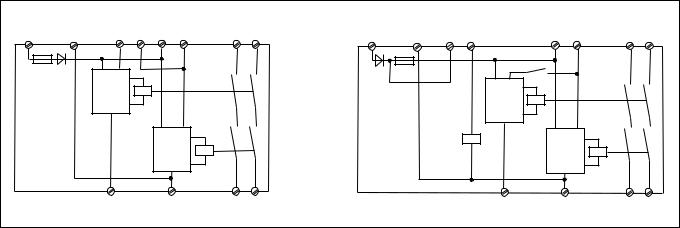
PNOZ X2, PNOZ X2.1 |
|
|
|
|
PNOZ X2.2 |
|
|
|
|
|||
A1 (L+) |
A2 (L-) |
S34 S33 |
S11 S12 |
13 |
23 |
A1 (L+) |
A2 (L-) |
S33 S34 |
S11 S12 |
13 |
23 |
|
|
|
|
|
|
|
|
|
|
K3 |
|
|
|
|
|
Start |
K1 |
|
|
|
|
|
K1 |
|
|
|
|
|
|
|
|
|
|
|
Start |
|
|
||
|
|
Unit |
|
|
|
|
|
|
|
|
||
|
|
|
|
|
|
|
|
|
|
|
||
|
|
|
|
|
|
|
|
|
Unit |
|
|
|
|
|
|
|
|
|
|
|
|
K3 |
|
|
|
|
|
|
|
Start |
K2 |
|
|
|
|
Start |
K2 |
|
|
|
|
|
Unit |
|
|
|
|
|
Unit |
|
|
|
|
S22 |
|
S21 |
14 |
24 |
|
|
S22 |
S21 |
14 |
24 |
Fig. 1: Innenschaltbild/Internal Wiring Diagram/Schéma de principe |
|
|
|
|
|
|
||||||
Betriebsarten:
•Einkanaliger Betrieb: Eingangsbeschaltung nach VDE 0113
Teil 1 und EN 60204-1; keine Redundanz im Eingangskreis; Erdschlüsse im Startkreis werden erkannt. Bei Erdschlüssen im Not-Halt-Kreis löst die Sicherung der Versorgungsspannung aus.
•Zweikanaliger Betrieb: Redundanter Eingangskreis, Erdschlüsse im Tasterkreis und Querschlüsse zwischen den Tasterkontakten werden erkannt.
•Nur PNOZ X2.1: automatischer Start: Gerät ist aktiv, sobald Eingangskreis geschlossen ist.
•Manueller Start: Gerät ist erst dann aktiv, wenn ein Starttaster betätigt oder ein
Startkontakt geschlossen wird.
•Nur PNOZ X2/X2.2: manueller Start mit Überwachung: vor dem Schließen des Startkontakts muss die Versorgungsspannung anliegen. Das Gerät ist erst aktiv, wenn danach der Starttaster betätigt wurde. Dadurch ist eine automatische Aktivierung durch Überbrückung des
Starttasters ausgeschlosssen.
Operating Modes
•Single-channel operation: Input wiring according to VDE 0113 part 1 and
EN 60204-1, no redundancy in the input circuit. Earth faults are detected in the reset circuit. Earth faults in the Emergency
Stop circuit trigger the internal electronic fuse.
•Two-channel operation: Redundancy in the input circuit. Earth faults in the Emergency
Stop circuit and shorts across the emergency stop push button are also detected.
•Only PNOZ X2.1: Automatic reset: Unit is active as soon as the input circuit is closed.
•Manual reset: Unit is only active when a reset button has been pressed or reset contact is closed.
•Only PNOZ X2/X2.2: monitored manual reset: The operating voltage must be applied before the closing of start/reset contacts. The unit is only active if after, the reset button is pressed. This prevents automatic reset and will detect stuck or short-circuited reset button.
Modes de fonctionnement
•Commande par 1 canal : conforme aux prescriptions de la EN 60 204-1 pas de redondance dans le circuit d’entrée. La mise à la terre du circuit de réarmement est détectée. En cas de mise à la terre des circuits d'entrée, le fusible électronique déclenche.
•Commande par 2 canaux: circuit d’entrée redondant. La mise à la terre et les courtscircuits entre les contacts sont détectées.
•PNOZ X2.1 uniquement: réarmement automatique : le relais est activé dès la fermeture des canaux d’entrée.
•Réarmement manuel : le relais n’est activé qu’après une impulsion sur un poussoir de validation.
•PNOZ X2/X2.2 uniquement: réarmement manuel auto-contrôlé: La tension d'alimentation doit être avant la fermeture du circuit de réarmement. Le relais n'est alors activé qu'après une impulsion sur le poussoir de réarmement. De ce fait un réarmement automatique ou un pontage du poussoir de validation est impossible.
- 2 -

•Nur PNOZ X2.2: Die Starteingänge beliebig vieler Geräte können parallel an einen oder mehrere Starttaster gelegt werden. Parallel startende Geräte müssen an dieselbe Spannungsversorgung angeschlossen werden.
•Kontaktvervielfachung und -verstärkung durch Anschluss von externen Schützen
•Only PNOZ X2.2: Start inputs can be connected in parallel to one or more start buttons. As many units as required may be used. Units that start in parallel must be connected to the same supply voltage.
•Increase in the number of available contacts by connection of external contactors/relays.
•PNOZ X2.2 uniquement: les entrées de réarmement de plusieurs appareils peuvent être câbles en parallèle sur un ou plusieurs poussoirs de réarmement.
Les appareils réarmés en parallèle doivent être alimentés par la même tension d’alimentation.
•Augmentation du nombre de contacts ou du pouvoir de coupure par l’utilisation de contacteurs externes.
Montage |
Installation |
Montage |
Das Sicherheitsschaltgerät muss in einen |
The safety relay must be panel mounted |
Le relais doit être monté en armoire ayant |
Schaltschrank mit einer Schutzart von mind. |
(min. IP54). There is a notch on the rear of |
un indice de protection mini IP54. Sa face |
IP54 eingebaut werden. Zur Befestigung auf |
the unit for DIN-Rail attachment. |
arrière permet un montage sur rail DIN. |
einer Normschiene dient ein Rastelement |
|
|
auf der Rückseite des Geräts. |
|
|
Inbetriebnahme
Beachten Sie bei der Inbetriebnahme:
•Vor die Ausgangskontakte eine Sicherung (s. techn. Daten) schalten, um das Verschweißen der Kontakte zu verhindern.
•Berechnung der max. Leitungslänge Imax im Eingangskreis:
Imax = Rlmax
Rl / km
Rlmax = max. Gesamtleitungswiderstand (s. technische Daten)
Rl /km = Leitungswiderstand/km
Da die Funktion Querschlusserkennung nicht einfehlersicher ist, wird sie von Pilz während der Endkontrolle geprüft. Eine Überprüfung nach der Installation des Geräts ist wie folgt möglich:
1.Gerät betriebsbereit (Ausgangskontakte geschlossen)
2.Die Testklemmen S12/S22 zur Querschlussprüfung kurzschließen.
3.Die Sicherung im Gerät muss auslösen und die Ausgangskontakte öffnen. Leitungslängen in der Größenordnung der
Maximallänge können das Auslösen der Sicherung um bis zu 2 Minuten verzögern.
4.Sicherung wieder zurücksetzen: den
Kurzschluss entfernen und die Versorgungsspannung für ca. 1 Minute abschalten.
•Leitungsmaterial aus Kupferdraht mit einer Temperaturbeständigkeit von 60/75 °C verwenden.
•Sorgen Sie beim Anschluss von magnetisch wirkenden, auf Reedkontakten basierenden Näherungsschaltern dafür, dass der max. Einschaltspitzenstrom (am
Eingangskreis) den Näherungsschalter nicht überlastet.
•Angaben im Kapitel „Technische Daten“ unbedingt einhalten.
Ablauf:
•Versorgungsspannung: Versorgungsspannung an Klemmen A1 und A2 anlegen
•Startkreis:
-nur PNOZ X2.1: Automatischer Start:
S33-S34 brücken
-Manueller Start (mit Überwachung bei PNOZ X2):
Taster an S33-S34 anschließen
-nur PNOZ X2.2: Paralleler Start mehrerer Geräte: Die Starteingänge S33 und S34 beliebig vieler Geräte parallelschalten. Einen oder mehrere Starttaster zwischen den Anschlüssen S33 und S34 einfügen. Alle Geräte müssen an derselben Spannungsversorgung betrieben werden.
Operation
Please note for operation:
•To prevent a welding together of the contacts, a fuse (see technical detail) must be connected before the output contacts.
•Calculate the max. Cable runs Imax in the input circuit:
Imax = Rlmax
Rl / km
Rlmax = Max. Total cable resistance (see technical details)
Rl /km = Cable resistance/km As the function for detecting shorts
across the inputs is not failsafe, it is tested by Pilz during the final control check. However, a test is possible after installing the unit and it can be carried out as follows:
1.Unit ready for operation (output contacts closed)
2.Short circuit the test (connection) terminals S12/S22 for detecting shorts across the inputs
3.The unit‘s fuse must be triggered and the output contacts must open. Cable lengths in the scale of the maximum length can delay the fuse triggering for up to 2 minutes.
4.Reset the fuse: remove the short circuit and switch off the operating voltage for approx. 1 minute.
•Use copper wiring that will withstand
60/75 °C.
•When connecting magnetically operated, reed proximity switches, ensure that the max. peak inrush current (on the input circuit) does not overload the proximity switch.
•Important details in the section "Technical
Data“ should be noted and adhered to.
To operate:
•Supply operating voltage:
Connect the operating voltage to terminals A1 and A2
•Reset circuit:
-only PNOZ X2.1: Automatic reset:
Bridge S33-S34
-Manual reset (PNOZ X2 with monitoring): Connect button to S33-S34
-only PNOZ X2.2: Starting several units in parallel: Connect in parallel start inputs S33 and S34 on as many units as required. Add one or more start buttons between the connections S33 and S34. All units must be operated at the same supply voltage.
-3 -
Mise en oeuvre
Remarques préliminaires :
•Protection de contacts de sortie par des fusibles (voir les caractéristiques techniques) pour éviter leur soudage
•Calcular les longueurs de câblage max
Imax dans le circuit d’entrée:
Imax = Rlmax
Rl / km
Rlmax = résistivité de câblage totale max.
(voir les caractéristiques techniques)
Rl /km = résistivité de câblage/km
La fonction de détection de court-circuit est testé par Pilz lors du contrôle final. Un test sur site est possible de la façon suivante :
1.Appareil en fonction (contacts de sortie fermés)
2.Court-circuiter les bornes de raccordement nécessaires au test S12/ S22
3.Le fusible interne du relais doit déclencher et les contacts de sortie doivent s‘ouvrir. Le temps de réponse du fuisible peut aller jusqu‘à 2 min. si les longueurs de câblage sont proches des valeurs maximales.
4.Réarmement du fusible : enlever le court-circuit et couper l‘alimentation du relais pendant au moins 1 min.
•Utiliser uniquement des fils de cablâge en cuivre 60/75 °C.
•Lors du raccordement de détecteurs de proximité magnétiques, basés sur des contacts Reed, veuillez vous assurer que le courant de crête max. à la mise sous tension (sur le circuit d'entrée) ne surcharge pas les détecteurs de proximité.
•Respecter les données indiquées dans le chap. „Caractéristiques techniques“.
Mise en oeuvre :
•Tension d’alimentation: amener la tension d’alimentation sur A1 et A2
•Circuit de réarmement:
-PNOZ X2.1 uniquement: réarmement automatique: pontage des bornes S33-
S34
-Réarmement manuel (auto-contrôlé sur
PNOZ X2): câblage d'un poussoir sur
S33-S34
-PNOZ X2.2 uniquement: Réarmement parallèle de plusieurs appareils :
Câbler en parallèle les bornes S33-S34 des différents appareils. Inserer un
ou plusieurs BP de réarmement entre les bornes S33-S34. Tous les appareils doivent être raccordés à la même tension d’alimentation.

•Eingangskreis:
-Einkanalig:
Öffnerkontakt von Auslöseelement zwischen Plusklemme (L+) der Versorgungsspannung und Klemme A1 anschließen, S11-S12 und S21-S22 brücken
-Zweikanalig: Öffnerkontakt von Auslöseelement an S11-S12 und S21S22 anschließen
•Rückführkreis:
Externe Schütze in Reihe zu Startkreis
S33-S34 anschließen
Die Sicherheitskontakte sind aktiviert (geschlossen). Die Statusanzeigen für "CH.1", "CH.2" leuchten. Das Gerät ist betriebsbereit.
Wird der Eingangskreis geöffnet, öffnen die Sicherheitskontakte 13-14/23-24. Die
Statusanzeige erlischt.
Wieder aktivieren
•Eingangskreis schließen.
•Bei manuellem Start zusätzlich Taster zwischen S33 und S34 betätigen.
Die Statusanzeigen leuchten wieder, die Sicherheitskontakte sind geschlossen.
•Input circuit:
-Single-channel: Connect N/C contact from safety switch between the positive terminal (L+) of the operating voltage and terminal A1, link S11-S12 and S21S22.
-Two-channel: Connect N/C contact from safety switch (e.g. EmergencyStop) to S11-S12 and S21-S22.
•Feedback control loop:
Connect external contactors/relays in series with reset circuit S33-S34.
The safety contacts are activated (closed). The status indicators "CH.1" and "CH.2" are illuminated. The unit is ready for operation. If the input circuit is opened, the safety contacts 13-14/23-24 open. The status indicator goes out.
Reactivation
•Close the input circuit.
•For manual reset press the button
between S33-S34.
The status indicators illuminate once more, the safety contacts are closed.
•Circuits d’entrée:
-Commande par 1 canal : câblage du contact à ouverture entre le potentiel (L+) de la tension d'alimentation et la borne A1 (+), pontage entre S11-S12 et S21-S22
-Commande par 2 canaux: câblage des contacts à ouverture entre S11-S12 et S21-S22
•Boucle de retour:
Câblage en série des contacts externes
dans le circuit de rèarmement S33-S34 Les contacts de sécurité se ferment. Les LEDs "CH.1" et "CH.2" sont allumées.
L’appareil est prêt à fonctionner.
Si le circuit d’entrée est ouvert, les contacts de sécurité retombent. Les LEDs s’éteignent.
Remise en route :
•fermer le circuit d’entrée
•en cas de réarmement manuel, appuyer sur le poussoir de validation entre S33-
S34.
Les LEDs sont à nouveau allumées. Les contacts de sécurité sont fermées.
Anwendung
In Fig. 2 ... Fig. 6 sind Anschlussbeispiele für Not-Halt-Beschaltung mit automatischem und manuellem Start, Schutztüransteuerungen sowie Kontaktvervielfachung durch externe Schütze.
Application
In Fig.2...Fig.6 are connection examples for
Emergency Stop wiring with automatic and manual reset. Safety gate control as well as contact expansion via external contactors.
Utilisation
Dans les figures 2 à 6 sont représentés les différents cablages possibles du PNOZ X2/ X2.1 : poussoirs AU avec réarmement automatique et surveillance du circuit de réarmement, interrupteur de position et augmentation du nombre des contacts par contacteurs externes.
S11 |
S21 |
S33 |
S11 |
S21 S33 |
S11 |
S33 |
|
|
|
|
|
S1 |
|
S1 |
|
S3 |
S1 |
|
S12 S3 |
|
|
|
|
|
|||
|
|
|
|
|
S21 |
|
|
|
|
|
|
S2 |
|
S12 S22 |
S34 |
S12 S22 S34 |
S22 |
S34 |
||
Fig. 2: Eingangskreis zweikanalig, manueller Start/Two-channel input circuit, manual reset/Commande par 2 canaux, réarmement manuel
UB
(L+) S11 S21 S33
S1
S3
Fig. 3: nur bei PNOZ X2.1: automat. Start/
Only PNOZ X2.1: automatic reset/
PNOZ X2.1 uniquement: réarmement automatique
1L1
K4 K5
S33 S34 13
14
A1 |
S12 |
S22 |
S34 |
|
K4 |
|
K5 |
|
|
|
|
|
|
|
|
||||||
|
|
|
|
|
|
|
|
|
||
|
|
|
|
1L2 |
|
|
|
|
|
|
|
|
|
|
|
|
|
|
|
|
|
Fig. 5: Eingangskreis einkanalig, manueller |
Fig. 6: Anschlussbeispiel für externe |
|||||||||
Start/Single-channel input circuit, manual |
Schütze, einkanalig/Connection example for |
|||||||||
reset/Commande par 1 canal, réarmement |
external contactors/relays, single-channel/ |
|||||||||
manuel |
|
|
|
Branchement contacteurs externes, |
||||||
|
|
|
|
commande par 1 canal |
|
|
|
|
|
|
Fig. 4: Schutztürsteuerung zweikanalig, manueller Start/Dual-channel safety gate control, manual reset/Surveillance de protecteur, commande par 2 canaux
betätigtes Element/Switch activated/élément actionné
Tür nicht geschlossen/Gate open/porte ouverte
Tür geschlossen/Gate closed/ porte fermée
S1/S2: Not-Halt- bzw. Schutztürschalter/ Emergency Stop Button, Safety
Gate Limit Switch/Poussoir AU, détecteurs de position
S3: Starttaster/Reset button/Poussoir de réarmement
- 4 -

Fehler - Störungen
•Erdschluss
Die Versorgungsspannung bricht zusammen und die Sicherheitskontakte werden über eine elektronische Sicherung geöffnet. Nach Wegfall der Störungsursache und Abschalten der Versorgungsspannung für ca. 1 Minute ist das Gerät wieder betriebsbereit.
•nur PNOZ X2.2: ein Erdschluss im Startkreis führt zum unabgesicherten Kurzschluss der Versorgungsspannung.
•Fehlfunktionen der Kontakte: Bei verschweißten Kontakten ist nach Öffnen des
Eingangskreises keine neue Aktivierung möglich.
•LED "Power" leuchtet nicht: Kurzschluss oder fehlende Versorgungsspannung
Faults
•Earth fault
Supply voltage fails and the safety contacts are opened via an electronic fuse. Once the cause of the fault has been removed and operating voltage is switched off, the unit will be ready for operation after approximately 1 minute.
•only PNOZ X2.2: An earth fault in the start circuit will lead to a short circuit of the supply voltage. This will not be failsafe.
•Contact failure: In the case of welded contacts, no further activation is possible following an opening of the input circuit.
•LED "Power" is not illuminated if shortcircuit or the supply voltage is lost.
Erreurs - Défaillances
•Défaut de masse
La tension d’alimentation chute et les contacts de sécurité sont ouverts par un fusible électronique. Une fois la cause du défaut éliminée et la tension d’alimentation coupée, l’appareil est à nouveau prêt à fonctionner après environ 1 minute.
•PNOZ X2.2 uniquement: une mise à la terre du circuit de réarmement entraîne un court-circuit de la tension d’alimentation
•Défaut de fonctionnement des contacts de sortie: en cas de soudage d’un contact lors de l’ouverture du circuit d’entrée, un nouvel réarmement est impossible.
•LED "Power" éteinte: tension d'alimentation non présente ou courtcircuit interne.
TechnischeDaten |
Technical details |
Caractéristiquestechniques |
|
|
|
|
|
Elektrische Daten |
Electrical data |
Données électriques |
|
Versorgungsspannung UB |
Supply voltage UB |
Tension d’alimentation UB |
AC: 24 V, DC: 24 V |
Spannungstoleranz UB |
Voltage tolerance UB |
Plage de la tension d'alimentation UB |
-15 %/+10 % |
Leistungsaufnahme bei UB |
Power consumption at UB |
Consommation pour UB |
4,5 VA; 2 W |
Frequenzbereich |
Frequency Range |
Fréquence |
AC: 50-60 Hz |
|
|
|
|
Restwelligkeit |
Residual ripple |
Ondulation résiduelle |
DC: 160% |
|
|
|
|
Spannung und Strom an |
Voltage and current at |
Tension et courant sur |
|
Eingangskreis |
input circuit |
circuit d’entrée |
25 mA |
Startkreis |
reset circuit |
circuit de réarmement |
50 mA |
Rückführkreis |
feedback loop |
boucle de retour |
50 mA |
Anzahl der Ausgangskontakte |
Number of output contacts |
Nombre de contacts de sortie |
|
Sicherheitskontakte (S) unverzögert |
Safety contacts (S) instantaneous |
Contacts de sécurité (F) instantanés |
2 |
Gebrauchskategorie nach |
Utilization category in accordance with |
Catégorie d’utilisation selon |
|
EN 60947-4-1 |
EN 60947-4-1 |
EN 60947-4-1 |
AC1: 240 V/0,01... 6 A/ |
|
|
|
1500 VA |
|
|
|
DC1: 24 V/0,01 ... 6 A/ |
|
|
|
150 W |
EN 60947-5-1 |
EN 60947-5-1 |
EN 60947-5-1 |
AC15: 230 V/5 A; |
(DC13: 6 Schaltspiele/Min.) |
(DC13: 6 cycles/min) |
(DC13: 6 manoeuvres/min) |
DC13: 24 V/4 A |
Konventioneller thermischer Strom |
Conventional thermal current |
Courant thermique |
|
|
|
conventionnel |
6 A |
Kontaktmaterial |
Contact material |
Matériau contact |
AgSnO2+ 0,2 µm Au |
Kontaktabsicherung extern |
External contact fuse protection |
Protection des contacts externe |
|
EN 60947-5-1 (IK = 1 kA) |
EN 60947-5-1 (IK = 1 kA) |
EN 60947-5-1 (IK = 1 kA) |
6 A link/quick acting/rapide |
Schmelzsicherung |
blow-out fuse |
fusible |
|
|
|
|
4 A träge/slow acting/ |
|
|
|
normal |
Sicherungsautomat,
Charakteristik B/C
Max. Gesamtleitungswiderstand
RImax
Eingangskreise, Startkreise einkanalig DC
einkanalig AC
zweikanalig mit Querschlusserkennung DC
zweikanalig mit Querschlusserkennung AC
Min. Eingangswiderstand im Einschaltmoment
Circuit breaker, |
|
Disjoncteur, |
characteristic B/C |
|
caractéristique B/C |
Max. overall cable resistance |
Résistance max. de l'ensemble du |
|
Rlmax |
|
câblage Rlmax |
input circuit, reset circuit |
|
circuit d’entrée, de réarmement |
single-channel DC |
|
commande par 1 canal DC |
single-channel AC |
|
commande par 1 canal AC |
dual-channel with detection of |
Commande par 2 canaux avec |
|
shorts across contacts |
DC |
détection des court-circuits DC |
dual-channel with detection of |
Commande par 2 canaux avec |
|
shorts across contacts |
AC |
détection des court-circuits AC |
Min. input resistance in the starting |
Résistance d'entrée min. au |
|
torque |
|
moment de la mise en marche |
24 V AC/DC, 4 A
150 Ohm
150 Ohm
15 Ohm
30 Ohm
PNOZ X2, PNOZ X2.2:
468 Ohm
PNOZ X2.1: 21 Ohm
Sicherheitstechnische Kenn- |
Safety-related characteristics of |
Caractéristiques techniques |
de |
|
daten der Sicherheitsausgänge |
the safety outputs |
sécurité des sorties de sécurité |
||
PL nach EN ISO 13849-1 |
PL in accordance with |
PL selon EN ISO 13849-1 |
|
|
|
EN ISO 13849-1 |
|
|
PL e (Cat. 4) |
Kategorie nach EN 954-1 |
Category in accordance with |
Catégorie selon EN 954-1 |
|
|
|
EN 954-1 |
|
|
Cat. 4 |
SIL CL nach EN IEC 62061 |
SIL CL in accordance with |
SIL CL selon EN IEC 62061 |
|
|
|
EN IEC 62061 |
|
|
SIL CL 3 |
PFH nach EN IEC 62061 |
PFH in accordance with |
PFH selon EN IEC 62061 |
|
|
|
EN IEC 62061 |
|
|
2,31E-09 |
SIL nach IEC 61511 |
SIL in accordance with IEC 61511 |
SIL selon IEC 61511 |
|
SIL 3 |
PFD nach IEC 61511 |
PFD in accordance with IEC 61511 |
PFD selon IEC 61511 |
|
2,03E-06 |
|
|
|
|
|
tM in Jahren |
tM in years |
tM en années |
20 |
|
- 5 -
 Loading...