


PNOZ 10

Nr. 17 987-01
Betriebsanleitung
Technical Instructions
Instruction d'emploi
PNOZ 10
Sicherheitsbestimmungen
• Das Gerät darf nur von Personen
installiert und in Betrieb genommen
werden, die mit dieser Betriebsanleitung
und den geltenden Vorschriften über
Arbeitssicherheit und Unfallverhütung
vertraut sind. Beachten Sie die VDE-
sowie die örtlichen Vorschriften, insbeson-
dere hinsichtlich Schutzmaßnahmen.
• Beim Transport, bei der Lagerung und im
Betrieb die Bedingungen nach EN 60068-
2-6, 04/95 einhalten (s. technische Daten).
• Durch Öffnen des Gehäuses oder eigen-
mächtige Umbauten erlischt jegliche Ge-
währleistung.
• Montieren Sie das Gerät in einen Schalt-
schrank; Staub und Feuchtigkeit können
sonst zu Beeinträchtigungen der Funktio-
nen führen.
• Sorgen Sie an allen Ausgangskontakten
bei kapazitiven und induktiven Lasten für
eine ausreichende Schutzbeschaltung.
Safety Regulations
• The unit may only be installed and
operated by personnel who are familiar
with both these instructions and the current
regulations for safety at work and accident
prevention. Follow CEN and local
regulations especially as regards
preventative measures.
• Transport, storage and operating conditions
should all conform to EN 60068-2-6, 04/95
(s. technical data).
• Any guarantee is void following opening of
the housing or unauthorised modifications.
• The unit should be panel mounted, other-
wise dampness or dust could lead to
function impairment.
• Adequate protection must be provided on
all output contacts with capacitive and
inductive loads.
Conseils préliminaires
• La mise en oeuvre de l’appareil doit être
effectuée par une personne spécialisée en
installations électriques, en tenant compte
des prescriptions des différentes normes
applicables (NF, EN, VDE...) notamment au
niveau des risques encourus en cas de
défaillance de l’équipement électrique.
• Transport, storage and operating conditions
should all conform to EN 60068-2-6, 04/95
(s. technical data).
• L’ouverture de l’appareil ou sa modifi-cation
annule automatiquement la garantie.
• L’appareil doit être monté dans une ar-
moire; l’humidité et la poussière pouvant
entraîner des aléas de fonctionnement.
• Vérifiez que le pouvoir de coupure des
contacts de sortie est suffisant en cas de
circuits capacitifs ou inductifs.
Bestimmungsgemäße Verwendung
Das Sicherheitsschaltgerät PNOZ 10 ist be-
stimmt für den Einsatz in
• NOT-AUS-Einrichtungen
• Sicherheitsstromkreisen nach VDE 0113
Teil 1, 11/98 und EN 60204-1, 12/97
(z. B. bei beweglichen Verdeckungen)
Authorised Applications
The Safety Relay PNOZ 10 is for use in:
• Emergency Stop installations.
• Safety Circuits according to VDE 0113
part 1, 11/98 and EN 60204-1, 12/97
(e.g. with movable guards).
Domaines d’utilisation
Le bloc logique de sécurité PNOZ 10 est
adapté pour:
• les circuits d’arrêt d’urgence
• les circuits de sécurité selon les normes
NF 79-130 et EN 60-204/1, 12/97 (ex.
protecteurs mobiles).
Gerätebeschreibung
Das Sicherheitsschaltgerät PNOZ 10 ist in
einem P-93-Gehäuse untergebracht. Es
stehen verschiedene Varianten für den
Betrieb mit Wechselspannung und eine
Variante für den Betrieb mit Gleichspannung
zur Verfügung.
Merkmale:
• Relaisausgänge: sechs Sicherheits-
kontakte (Schließer) und vier Hilfskontakte
(Öffner), zwangsgeführt
• Anschlußmöglichkeit für NOT-AUS-Taster,
Schutztürgrenztaster und Starttaster
• Netzanzeige
• Statusanzeige
• Rückführkreis zur Überwachung externer
Schütze
Das Schaltgerät erfüllt folgende Sicherheits-
anforderungen:
• Schaltung ist redundant mit Selbst-
überwachung aufgebaut.
• Sicherheitseinrichtung bleibt auch bei
Ausfall eines Bauteils wirksam.
• Bei jedem Ein-Aus-Zyklus der Maschine
wird automatisch überprüft, ob die Relais
der Sicherheitseinrichtung richtig öffnen
und schließen.
• AC- und DC-Schaltgeräte besitzen eine
elektronische Sicherung.
Description
The Safety Relay PNOZ 10 is enclosed in a
P-93 housing. There are different versions
available for AC operation and one for DC
operation.
Features:
• Relay outputs: six safety contacts (N/O)
and four auxiliary contacts (N/C), positive-
guided.
• Connections for Emergency Stop Button,
Safety Gate Limit Switch and Reset
Button.
• Power indicator
• Status Indicators.
• Feedback Control Loop for monitoring of
external contactors/relays.
The relay complies with the following safety
requirements:
• The circuit is redundant with built-in self-
monitoring.
• The safety function remains effective in
the case of a component failure.
• The correct opening and closing of the
safety function relays is tested automati-
cally in each on-off cycle.
• AC and DC relays are fitted with an
electronic fuse.
Description de l’appareil
Inséré dans un boîtier P93, le bloc logique
de sécurité PNOZ 10 est disponible en
différentes versions pour les tensions
d’alimentation alternatives et une version en
alimentation continue (24 VDC).
Autres particularités:
• Sorties disponibles: 6 contacts à ferme-
ture de sécurité et 4 contacts à ouverture
pour signalisation
• Bornes de raccordement pour poussoirs
AU, détecteurs de position et poussoir de
validation
• LEDs de visualisation des canaux d’entrée
et de la tension d’alimentation
• Boucle de retour pour l’auto-contrôle des
contacteurs externes
Le relais PNOZ 10 répond aux exigences
suivantes:
• conception redondante avec auto-
surveillance
• sécurité garantie même en cas de
défaillance d’un composant
• test cyclique (ouverture/fermeture des
relais internes) à chaque cycle Marche/
Arrêt de la machine
• fusible électronique (relais en AC et en
DC)
Funktionsbeschreibung
Das Schaltgerät PNOZ 10 dient dem
sicherheitsgerichteten Unterbrechen eines
Sicherheitsstromkreises. Nach Anlegen der
Versorgungsspannung, Brücke zwischen
Y1-Y2 und S12-S34 sowie geöffnetem
Eingangskreis geht Relais K3 in Wirk-
stellung.
• Eingangskreis geschlossen (z. B. NOT-
AUS-Taster nicht betätigt)
Relais K1 und K2 gehen über die
Schließer K3.1 und K3.2 in Wirkstellung
und halten sich selbst über K1.1 bzw.
K2.1. Die Statusanzeigen leuchten.
Durch Öffnen der Kontakte K1.2 und
K2.2 geht K3 nach Ablauf der Rück-
fallverzögerung von 90 ms in Ruhe-
stellung. Die Sicherheitskontakte (13-14/
23-24/33-34/43-44/53-54/63-64) sind ge-
schlossen, die Hilfskontakte (71-72/81-
82/91-92/01-02) sind geöffnet.
• Eingangskreis wird geöffnet (z. B. NOT-
AUS-Taster betätigt)
K1 und K2 fallen in die Ruhestellung
zurück. Die Sicherheitskontakte (13-14/
23-24/33-34/43-44/53-54/63-64) werden
redundant geöffnet, die Hilfskontakte (71-
72/81-82/91-92/01-02) geschlossen.
Function Description
The relay PNOZ 10 provides a safety-
oriented interruption of a safety circuit.
When the operating voltage is supplied, Y1 -
Y2 and S12 - S34 are bridged and the input
circuit is closed, relay K3 energises.
• Input circuit closed (e.g. Emergency Stop
Button not activated):
Relay K1 and K2 energise via the N/O
K3.1 and K3.2 and latch via K1.1/K2.1.
The status indicators illuminate. By
opening the contacts K1.1 and K2.2, K3
de-energises following the delay-on de-
energisation of 90 ms. The safety
contacts (13-14/23-24/33-34/43-44/53-54/
63-64) are closed, the auxiliary contacts
(71-72/81-82/91-92/01-02) are opened.
• Input circuit opened (e.g. Emergency Stop
Button activated):
K1 and K2 de-energise. The safety
contacts (13-14/23-24/33-34/43-44/53-54/
63-64) are opened redundantly, the
auxiliary contacts (71-72/81-82/91-92/01-
02) are closed.
Description du fonctionnement
Le relais PNOZ 10 assure de façon sure,
l’ouverture d’un circuit de sécurité. A la mise
sous tension du relais (A1-A2), si Y1-Y2 et
S12-S34 sont pontés et les canaux d’entrée
ouverts, le relais K3 colle.
• Fermeture des canaux d’entrée
(par ex. AU non actionné):
les relais K1 et K2 collent par l’inter-
médiaire des contacts K3.1 et K3.2 et
s’auto-maintiennent par K1.1 et K2.1. Les
LEDs de visualisation sont allumées.
L’ouverture des contacts K1.2 et K2.2 fait
retomber le relais K3 qui se maintient
environ 90 ms. Les contacts de sortie de
sécurité (13-14/23-24/33-34/43-44/53-54
et 63-64) se ferment, les contacts
d’information 71-72/81-82/91-92 et 01-02
s’ouvrent.
• Ouverture des canaux d’entrée (par ex.
action sur AU):
K1 et K2 retombent. Les contacts de sortie
(13-14/23-24/33-34/43-44/53-54/63-64)
s’ouvrent de façon redondante, les
contacts d’information (71-72/81-82/91-92/
01-02) se ferment.
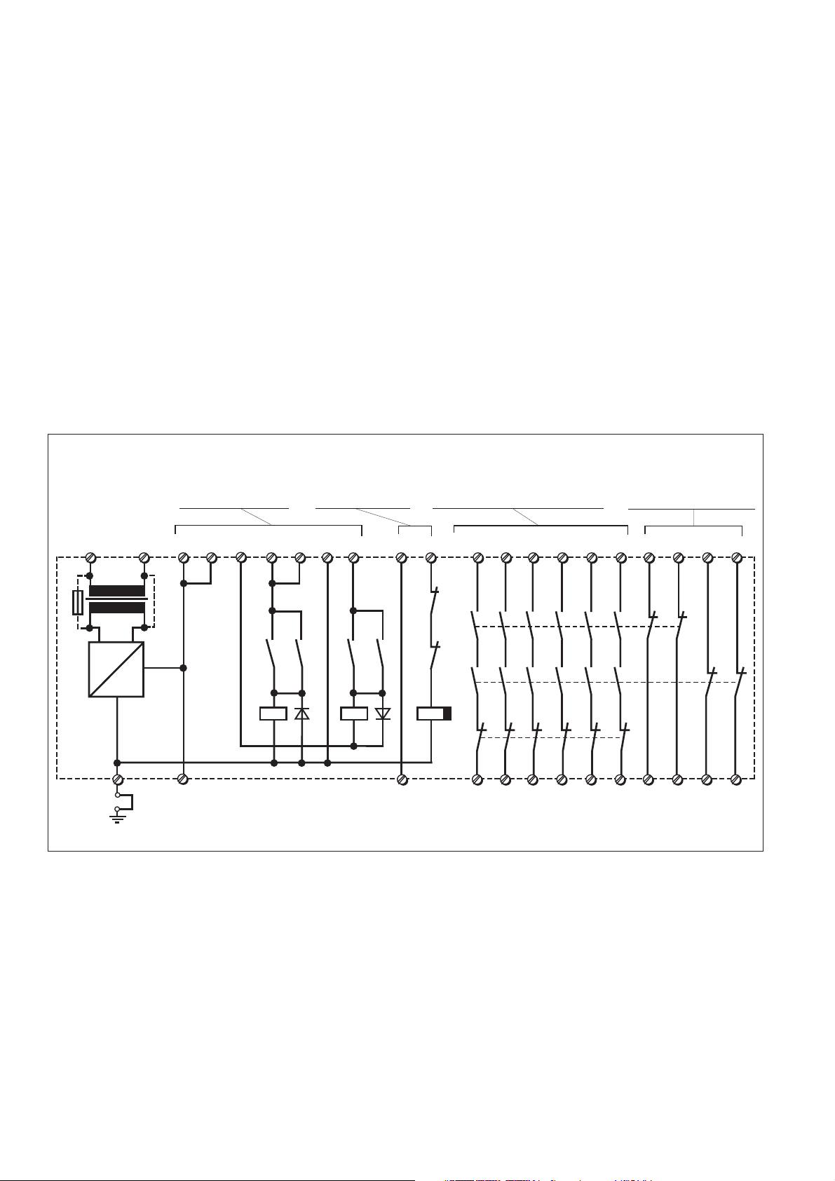
S11 13 23 33 71
14 24 34 72
K2
K1
K3
K2.2
K1.2
Y1
Y3
PNOZ 10
K3
+
~
=
F1
G1
S34
S33
K3.1 K3.2
S12S12 S22
K2
K2.1
K1
A2 (L-)A1 (L+)
K1.1
Rückführkreis
Feedback Control Loop
Boucle retour
NOT-AUS-Taster
Emergency Stop Button
Poussoir arrêt d'urgence
Sicherheitskontakte, zwangsgeführt
Safety Contacts, positive-guided
Contacts pour circuits de sécurité
Hilfsöffner für Sicherheits-
stromkreise unzulässig
Auxiliary N/C contacts,
unsuitable for safety circuits
Contact auxilaire ne pas utiliser
dans le circuits de sécurité
U
B
Eintaster, Reset, Poussoir VAL
43
44
53
54
63
64
81
82
91 01
92
02
S11 S21 Y2
Fig. 1: Innenschaltbild/Internal Wiring Diagram/Schéma de principe
Betriebsarten:
• Einkanaliger Betrieb: Eingangsbeschal-
tung nach VDE 0113 und EN 60204-1,
keine Redundanz im Eingangskreis,
Erdschlüsse im Tasterkreis werden
erkannt.
• Zweikanaliger Betrieb: Redundanter Ein-
gangskreis, Erdschlüsse im Tasterkreis
und Querschlüsse zwischen den Taster-
kontakten werden erkannt.
• Automatischer Start: Gerät ist aktiv,
sobald Eingangskreis geschlossen.
• Manueller Start: Gerät ist erst dann aktiv,
wenn ein Starttaster betätigt wird.
• Kontaktvervielfachung und -verstärkung
durch Anschluß von externen Schützen.
Operating Modes
• Single-channel operation: Input wiring
according to EN 60204-1, no redundancy in
the input circuit, earth faults are detected in
the emergency stop circuit.
• Two-channel operation: Redundancy in the
input circuit, earth faults in the emergency
stop circuit and shorts across the emer-
gency stop pushbutton will be detected.
• Automatic reset: Unit is active as soon as
the input circuit is closed.
• Manual reset: Unit is only active when a
start button has been pressed.
• Increase in the number of available con-
tacts by connection of external contactors/
relays.
Modes de fonctionnement
• Commande par 1 canal: conforme aux
prescriptions de la EN 60204-1, pas de
redondance dans le circuit d’entrée, la mise
à la terre du circuit d’entrée est détectée.
• Commande par 2 canaux: circuit d’entrée
redondant, la mise à la terre et les courts-
circuits entre les contacts sont détectés.
• Réarmement automatique: le relais est
activé dès la fermeture des canaux
d’entrée.
• Réarmement manuel: le relais n’est activé
qu’après une impulsion sur un poussoir de
validation.
• Augmentation du nombre de contacts ou
du pouvoir de coupure par l’utilisation de
contacteurs externes.
 Loading...