


 Loading...
PSEN cs4.1a/b/p/M12
PSEN sensor technology
Operating Manual-22187-EN-02
This document is a translation of the original document.
All rights to this documentation are reserved by Pilz GmbH & Co. KG. Copies may be made for internal purposes. Suggestions and comments for improving this documentation will be gratefully received.
Pilz®, PIT®, PMI®, PNOZ®, Primo®, PSEN®, PSS®, PVIS®, SafetyBUS p®, SafetyEYE®, SafetyNET p®, the spirit of safety® are registered and protected trademarks of Pilz GmbH & Co. KG in some countries.
 SD means Secure Digital

Content
Introduction |
4 |
Validity of documentation |
4 |
Retaining the documentation |
4 |
Definition of symbols |
4 |
|
|
Safety switch PSEN cs4.1 |
5 |
|
|
For your safety |
5 |
|
|
Unit features |
5 |
|
|
Function description |
6 |
Block diagram |
6 |
Operating distances |
7 |
Lateral and vertical offset |
7 |
|
|
Wiring |
8 |
Pin assignment, connector and cable |
8 |
Connection to evaluation devices |
8 |
Single connection |
9 |
Series connection |
10 |
Connection to PNOZ X, PNOZpower, PNOZsigma, PNOZelog |
11 |
Connection to PNOZmulti |
13 |
Connection to PSS |
13 |
|
|
Teaching in the actuator |
13 |
|
|
Installation |
14 |
Parallel assembly |
14 |
Orthogonal assembly |
16 |
|
|
Adjustment |
17 |
|
|
Operation |
17 |
Error display through flashing codes |
18 |
|
|
Dimensions in mm |
19 |
PSEN cs4.1a, PSEN cs4.1b |
19 |
PSEN cs4.1p |
19 |
PSEN cs4.1 M12/8-0.15m |
20 |
|
|
Technical details |
20 |
Safety characteristic data |
25 |
|
|
Order reference |
26 |
Operating Manual PSEN cs4.1a/b/p/M12 |
3 |
22187-EN-02 |
|
PSEN cs4.1a/b/p/M12
Introduction
Validity of documentation
This documentation is valid for the product PSEN cs4.1a/b/p/M12. It is valid until new documentation is published.
This operating manual explains the function and operation, describes the installation and provides guidelines on how to connect the product.
Retaining the documentation
This documentation is intended for instruction and should be retained for future reference.
Definition of symbols
Information that is particularly important is identified as follows:
DANGER!
This warning must be heeded! It warns of a hazardous situation that poses an immediate threat of serious injury and death and indicates preventive measures that can be taken.
WARNING!
This warning must be heeded! It warns of a hazardous situation that could lead to serious injury and death and indicates preventive measures that can be taken.
CAUTION!
This refers to a hazard that can lead to a less serious or minor injury plus material damage, and also provides information on preventive measures that can be taken.
NOTICE
This describes a situation in which the product or devices could be damaged and also provides information on preventive measures that can be taken. It also highlights areas within the text that are of particular importance.
INFORMATION
This gives advice on applications and provides information on special features.
Operating Manual PSEN cs4.1a/b/p/M12 |
4 |
22187-EN-02 |
|

PSEN cs4.1a/b/p/M12
Safety switch PSEN cs4.1
The safety switch meets the requirements in accordance with:
}EN 60204-1 and IEC 60204-1
}EN 60947-5-3 with the actuator PSEN cs4.1
}EN 62061: SIL CL 3
}EN ISO 13849-1: PL e and Cat. 4
The safety switch may only be used with the corresponding actuator PSEN cs4.1. The safety outputs must use 2-channel processing.
For your safety
}Only install and commission the unit if you have read and understood these operating instructions and are familiar with the applicable regulations for health and safety at work and accident prevention.
Ensure VDE and local regulations are met, especially those relating to safety.
}Any guarantee is rendered invalid if the housing is opened or unauthorised modifications are carried out.
}Do not remove the protective cap until you are just about to connect the unit.
Unit features
}Transponder technology
}Coding: fully coded
}Dual-channel operation
}2 safety inputs for series connection of multiple safety switches
}2 safety outputs
}1 signal output
}LED for:
–State of the actuator
–State of the inputs
–Supply voltage/fault
}1 direction of actuation
}Connection types:
–PSEN cs4.1a: Cable, 5 m
–PSEN cs4.1b: Cable, 10 m
–PSEN cs4.1p: 8 pin M8 connector
–PSEN cs4.1 M12/8-0.15m: Connector 8 pin M12
Operating Manual PSEN cs4.1a/b/p/M12 |
5 |
22187-EN-02 |
|

PSEN cs4.1a/b/p/M12
Function description
There is a high signal or a low signal at the safety outputs, depending on the position of the actuator and the state of the inputs. The signal output Y32 signals the position of the actuator.
State of the inputs and outputs:
Actuator in |
|
|
|
|
|
the response |
|
|
Safety out- |
Safety out- |
Signal out- |
range |
Input S11 |
Input S21 |
put 12 |
put 22 |
put Y32 |
Yes |
High |
Low |
High |
Low |
High |
|
|
|
|
|
|
Yes |
Low |
High |
Low |
High |
High |
|
|
|
|
|
|
Yes |
High |
High |
High |
High |
High |
|
|
|
|
|
|
Yes |
Low |
Low |
Low |
Low |
High |
|
|
|
|
|
|
No |
x |
x |
Low |
Low |
Low |
|
|
|
|
|
|
x: High or low signal
The outputs cannot be switched back on until there is a low signal at both inputs simultaneously.
Safety inputs S11 and S21 are monitored for feasibility. A high signal can be present at the inputs at offset times; the low signal must be present at both inputs simultaneously (partial operation lock).
Block diagram
A1 |
A2 |
S11 S21 |
|
|
|
|
|
Input |
|
|
|
|
|
|
|
Receiver |
Actuator |
Power |
& |
|
|
|
|
|
|
|
|
||
|
|
12 |
22 |
Y32 |
|
Operating Manual PSEN cs4.1a/b/p/M12 |
6 |
22187-EN-02 |
|

PSEN cs4.1a/b/p/M12
Operating distances
On |
Off |
Legend:
} : Lateral offset
} : Vertical offset
} : Switch states (y-axis) dependent on operating distances (x-axis)
}Sao: Assured operating distance: 8,0 mm
}So: Typical operating distance: 11,0 mm
}Sr: Typical release distance: 14,0 mm
}Sar: Assured release distance: 20,0 mm
Lateral and vertical offset
|
4 |
4 |
0 |
5 |
10 |
|
|
|
|
|
|||
3 |
|
|
|
|
-10 |
|
|
|
|
|
|
4 |
|
|
|
|
|
|
-8 |
|
|
|
|
|
|
|
|
2 |
-10 -8 -6 -4 0 4 6 8 10 mm |
|
|
-6 |
|
|
10 |
|
10 |
5 |
|
-4 |
|
|
|
|
|
|
|
|
5 |
|
5 |
|
|
0 |
|
0 |
|
0 |
|
|
4 |
|
|
|
|
|
|
6 |
4 |
|
|
|
|
|
8 |
|
|
|
|
|
|
|
|
1 |
|
|
6 |
|
10 |
|
|
|
|
10 mm |
|
||
|
|
|
0 |
5 |
|
|
Legend:
} : Hysteresis
} : Typical operating distance SO
} : Typical release distance Sr
} : Offset in mm
} : Switching distance in mm
} : Response range
Operating Manual PSEN cs4.1a/b/p/M12 |
7 |
22187-EN-02 |
|
PSEN cs4.1a/b/p/M12
Wiring
Please note:
}Information given in the "Technical details" must be followed.
}Calculation of the max. cable length lmax in the input circuit:
Imax = Rlmax
Rl / km
Rlmax = Max. overall cable resistance (see Technical details [ 20]
20]
Rl / km = cable resistance/km
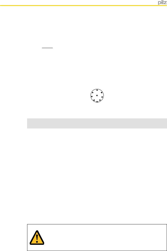
Pin assignment, connector and cable
|
|
|
5 |
|
|
|
6 |
4 |
|
|
|
7 |
8 |
|
|
|
3 |
|
|
|
|
1 |
2 |
|
|
|
|
|
|
Fig.: 8 pin M8/M12 connector |
|
|
|
|
|
|
|
|
|
|
Pin |
|
|
|
PIN |
designation |
Function |
|
Wire colour |
1 |
S21 |
Input, channel 2 |
White |
|
|
|
|
|
|
2 |
A1 |
+24 VUB |
|
Brown |
|
|
|
|
|
3 |
12 |
Output, channel 1 |
Green |
|
|
|
|
|
|
4 |
22 |
Output, channel 2 |
Yellow |
|
|
|
|
|
|
5 |
Y32 |
Signal output |
Grey |
|
|
|
|
|
|
6 |
S11 |
Input, channel 1 |
Pink |
|
|
|
|
|
|
7 |
A2 |
0 V UB |
|
Blue |
|
|
|
|
|
8 |
- |
Do not connect |
Red |
|
|
|
|
|
|
The wire colour also applies for the cable available from Pilz as an accessory.
Connection to evaluation devices
Please note:
}The power supply must meet the regulations for extra low voltages with safe separation (SELV, PELV).
}The inputs and outputs of the safety switch must have a safe separation to voltages over 60 V AC.
CAUTION!
The safety outputs must use 2-channel processing.
Operating Manual PSEN cs4.1a/b/p/M12 |
8 |
22187-EN-02 |
|

PSEN cs4.1a/b/p/M12
Single connection
Actuator |
Receiver |
|
Evaluation device |
Operating Manual PSEN cs4.1a/b/p/M12 |
9 |
22187-EN-02 |
|
Loading...