


S1SW P 24-240VACDC

- 1 -
Sicherheitsbestimmungen
• Das Gerät darf nur von einer Elektro-
fachkraft oder unterwiesenen Personen
installiert und in Betrieb genommen
werden, die mit dieser Betriebsanleitung
und den geltenden Vorschriften über
Arbeitssicherheit und Unfallverhütung
vertraut sind. Beachten Sie die VDE-
sowie die örtlichen Vorschriften, insbeson-
dere hinsichtlich der Schutzmaßnahmen.
• Halten Sie beim Transport, der Lagerung
und im Betrieb die Bedingungen ein, wie
sie unter den technischen Daten angege-
ben sind.
• Entsorgen Sie das Gerät nach Ablauf
seiner Lebensdauer sachgerecht.
• Durch Öffnen des Gehäuses oder
eigenmächtige Umbauten erlischt die
Gewährleistung.
• Bauen Sie das Gerät in einen Schalt-
schrank mit der Schutzart IP54 ein.
• Sorgen Sie bei allen Ausgangskontakten
bei kapazitiven und induktiven Lasten für
eine ausreichende Schutzbeschaltung.
• Diese Bedienungsanleitung dient der
Instruktion. Bewahren Sie sie für künftige
Verwendung auf.
Safety regulations
• Electrical connections should be made by
those who are qualified electrical
engineers or have received sufficient
training and are familiar with the
information in these operating instructions
and the relevant regulations concerning
health and safety at work. Ensure VDE
and local regulations are met, especially
those relating to safety.
• Transport, storage and operating
conditions should conform to the standards
stated under Technical Details.
• The system must be disposed of properly
when it reaches the end of its service life.
• The guarantee is rendered invalid if the
housing is opened or unauthorised
modifications carried out.
• The device should be installed in a control
cabinet with protection type IP54.
• Sufficient fuse protection must be provided
on all output contacts with capacitive and
inductive loads.
• These operating instructions are intended
for instruction and should be retained for
future reference.
Conseils préliminaires
• L’installation et la mise en œuvre de
l’appareil doivent être effectuées par un
électricien ou une personne spécialisée en
installations électriques, en tenant compte
du manuel d’utilisation et des prescriptions
en vigueur au sujet de la sécurité du travail
et de la protection contre les accidents.
Veuillez respecter les règlements VDE
ainsi que les règlements locaux,
notamment en ce qui concerne les
mesures de protection.
• Respecter les exigences des normes
specifiées lors du transport,
du stockage et de l’utilisation de l’appareil
(voir Caractéristiques techniques).
• A la fin de sa durée de service, éliminez
l’appareil conformément aux prescriptions.
• L’ouverture du boîtier ou des modifica-
tions non autorisées annulent automa-
tiquement la clause de garantie.
• Installez l’appareil dans une armoire
électrique de classe de protection IP54.
• Assurez-vous du pouvoir de coupure des
contacts de sortie en cas de charges
inductives ou capacitives.
• Le manuel d’utilisation sert à l’instruction.
Veuillez conserver ce manuel pour une
utilisation ultérieure.
Utilisation conforme
Le contrôleur d’arrêt S1SW P permet de
détecter l’arrêt d’un moteur. Le S1SW P est
conçu pour une utilisation en détecteur
d’arrêt sur des installations avec des parties
de machine ou des outils dangereux.
Intended use
The S1SW P is used for monitoring standstill
of motors. The S1SW P is intended for use
as a standstill monitor in plants with
dangerous machine parts or tools.
Bestimmungsgemäße Verwendung
Der Stillstandswächter S1SW P dient als
Einrichtung zur Stillstandsüberwachung von
Motoren. Das S1SW P ist bestimmt für den
Einsatz in Stillstandsüberwachungen an
Anlagen mit gefährlichen Maschinenteilen
oder Werkzeugen.
Gerätebeschreibung
Der Stillstandswächter ist in einem S-99-
Gehäuse untergebracht.
Merkmale:
• Relaisausgänge :
2 Hilfskontakte (U)
• Potentiometer „ta“ zum Einstellen der
Auslaufüberwachungszeit
• Potentiometer „Level in %“ zum Einstellen
der Ansprechempfindlichkeit U
an
(Stillstandsschwelle)
• LED-Anzeige „PWR/FLT“ für Betrieb/
Störung
• LED-Anzeige „STOP“ für Stillstand
• Schiebeschalter „x1/x2“ zur Messbereichs-
verdoppelung
Der Stillstandswächter S1SW P arbeitet nach
dem Arbeitsstromprinzip, d. h. das Gerät ist
für Sicherheitsanwendungen nur mit
Einschränkung geeignet. Für eine
Sicherheitsschaltung gemäß VDE 0113
empfehlen wir die Sicherheitsschaltgeräte
PSWZ oder PDWZ.
Unit description
The standstill monitor is enclosed in an S-99
housing.
Features:
• Relay outputs:
2 auxiliary contacts (C/O)
• Potentiometer „ta“ to set the rundown
monitoring time
• Potentiometer „Level in %“ to set the
response sensitivity (standstill threshold)
• LED for operation/fault, „PWR/FLT“
• LED for standstill, „STOP“
• Slide switch „x1/x2“ for doubling the
measuring range
The S1SW P operates to normally de-
energised mode, i.e. the device has limited
use in process control and safety
applications. We would recommend using the
PSWZ or the PDWZ in safety circuits in
accordance with VDE 0113.
Description de l’appareil
Le contrôleur d’arrêt est intégré dans un
boîtier S-97.
Particularités :
• Sorties de relais :
2 contacts d’information (OF)
• Potentiomètre « ta » pour régler la durée
de contrôle du temps d’arrêt
• Potentiomètre « Level in % » pour régler
la
sensibilité d’enclenchement (seuil d’arrêt)
• LED de visualisation du fonctionnement /
des pannes, « PWR/FLT »
• LED de visualisation d’arrêt, « STOP »
• Sélecteur « x1/x2 » pour le doublement de
la plage de mesure
Le contrôleur d’arrêt S1SW P fonctionne par
excitation du relais de sortie; son utilisation
pour des applications de sécurité n’est
possible que sous certaines conditions.
Pour des applications de sécurité selon
VDE 0113, nous recommandons les relais de
sécurité PSWZ ou PDWZ.
20 120-01
S1SW P
4
D Betriebsanleitung
4
GB Operating instructions
4
F Manuel d'utilisation
- 2 -
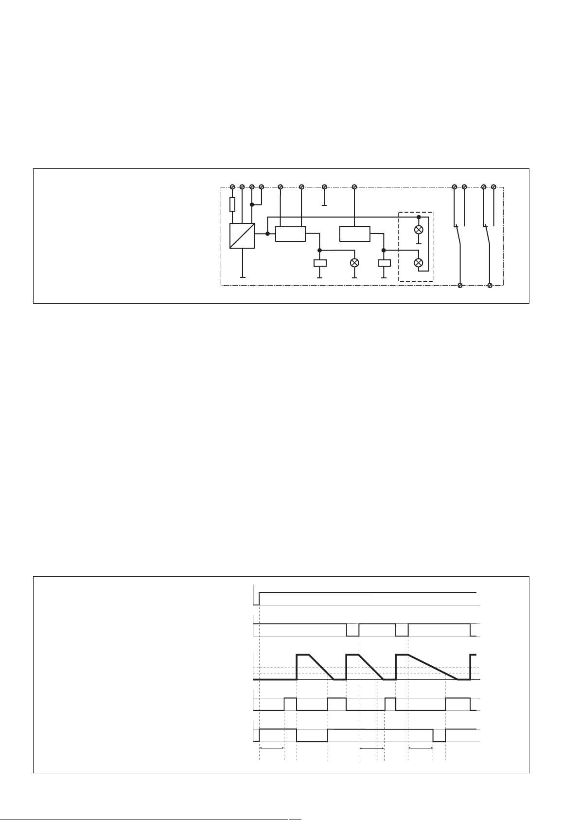
Funktionsbeschreibung
Das Gerät erfasst die in der Motorwicklung
induzierte Spannung U
M
, die beim Auslaufen
der Motorwelle entsteht. Wenn die Spannung
den eingestellten Ansprechwert U
an
unter-
schreitet, meldet das S1SW P Stillstand.
Nach dem Einschalten der Versorgungs-
spannung U
B
und bei Motorstillstand (U
M
<
U
an
) ziehen die Ausgangsrelais K1 und K2
an. Nach Anlauf des Motors fällt K1 ab (U
M
>
U
ab
). Der weitere Ablauf ist abhängig von der
verwendeten Betriebsart.
Fig. 2: Funktionsdiagramm/Pulse diagram/
Diagramme fonctionnel
Fig. 1: Schematisches Schaltbild/Wiring
diagram/Schéma interne
Betriebsarten
• Stillstandsüberwachung ohne Auslauf-
überwachung
Die Klemmen Y3-Y4 sind gebrückt.
Das Relais K1 zieht wieder an, wenn der
Motor abgeschaltet und die vom Motor
induzierte Spannung U
M
den Ansprechwert
U
an
unterschreitet (Stillstand). Der
Hilfskontakt 11-12 öffnet, 11-14 schließt.
• Stillstands- und Auslaufüberwachung
An die Klemmen Y3-Y4 ist der Öffner-
kontakt des Motorschützes angeschlos-
sen.
Durch Abschalten des Motors wird der
Öffnerkontakt des Motorschützes ge-
schlossen und dadurch wird die
Auslaufüberwachungszeit t
a
gestartet.
Wenn die vom Motor induzierte Spannung
U
M
innerhalb dieser Überwachungszeit den
Ansprechwert U
an
unterschreitet, zieht
Relais K1 an. Der Hilfskontakt 11-12
öffnet, 11-14 schließt. Wenn die Spannung
nach Ablauf der Überwachungszeit noch
größer als der Ansprechwert U
an
ist, fällt
Relais K2 ab. Der Hilfskontakt 21-24
öffnet, 21-22 schließt.
~
=
+
K1
14
11 21
K2
12
24
22
U
M
< U
an
t < t
a
Y4A1 Y3U
V
B3 A2
K1
K2
Stand-
still
(gr)
Flt
(rd)
Pwr
(gr)
A2
U
B
U
an
U
ab
U
M
ta
ta
K1
K2
Y3-Y4
ta
Function description
The device measures the regenerated
voltage U
M
induced from the motor during the
rundown period. If voltage falls below the set
response value U
an
, the S1SW P will detect
standstill.
Once the operating voltage U
B
has been
applied and the motor is at standstill (U
M
<
U
an
), the output relays K1 and K2 energise.
Once he motor has started (U
M
> U
ab
), the
output relays de-energise. An additional
cycle will depend on the type of operating
mode used.
Operating modes
• Standstill monitoring without rundown
monitoring
Terminals Y3-Y4 are linked.
Relay K1 energises again if the motor is
switched off and the induced voltage U
M
from the motor falls below the response
value U
an
(standstill). The auxiliary contact
11-12 opens and 11-14 closes.
• Standstill and rundown monitoring
The N/C contact of the motor’s relay is
connected to terminals Y3-Y4.
If the motor is switched off the N/C contact
of the motor’s relay is closed and in doing
so rundown monitoring t
a
is started. If the
induced voltage U
M
from the motor falls
below the response value U
an
within the
monitoring time, relay K1 energises. The
auxiliary contact 11-12 opens and 11-14
closes. If the voltage is still greater than
the response value U
an
once monitoring
time has elapsed, the relay K2 de-
energises. The auxiliary contact 21-24
opens and 21-22 closes.
Description du fonctionnement
L’appareil mesure la tension rémanente U
M
qui est générée dans les enroulements du
moteur lors de sa décélération. Lorsque la
tension mesurée passe en dessous de la
valeur d’enclenchement définie U
an
, le
S1SW P signale l’arrêt.
A la mise sous tension du relais U
B
et en cas
d’arrêt du moteur (U
M
< U
an
), les relais de
sortie K1 et K2 passent en position travail.
Après le démarrage du moteur, K1 retombe
(U
M
> U
ab
). Le déroulement ultérieur dépend
du mode de fonctionnement utilisé.
Modes de fonctionnement
• Contrôle de l’arrêt sans contrôle du temps
d’arrêt
Les bornes Y3-Y4 sont pontées.
Le relais K1 repasse en position travail,
lorsque le moteur est coupé et que la
tension U
M
induite par le moteur passe en
dessous de la valeur d’enclenchement U
an
(arrêt). Le contact d’information 11-9
s’ouvre, 11-10 se ferme.
• Contrôle de l’arrêt et du temps d’arrêt
Le contact repos du contacteur moteur est
raccordé au bornes Y3-Y4.
En arrêtant le moteur, le contact repos du
contacteur moteur ferme le circuit aux
bornes Y3-Y4, ce qui déclenche le début
de la durée de contrôle du temps d’arrêt t
a
.
Si la tension U
M
induite par le moteur au
cours de cette durée de contrôle passe en
dessous de la valeur d’enclenchement U
an
,
le relais K1 passe en position travail. Le
contact d’information 11-12 s’ouvre,
11-14 se ferme. Si la tension est encore
supérieure à la valeur d’enclenchement
U
an
à l’issue de la durée de contrôle, le
relais K2 retombe. Le contact d’informa-
tion 21-24 s’ouvre, 21-22 se ferme.
 Loading...