


 Loading...
PSSu H PLC1 FS SN SD(T)(R)
Control system PSSuniversal PLC
Operating Manual21939EN10
This document is a translation of the original document.
All rights to this documentation are reserved by Pilz GmbH & Co. KG. Copies may be made for internal purposes. Suggestions and comments for improving this documentation will be gratefully received.
Pilz®, PIT®, PMI®, PNOZ®, Primo®, PSEN®, PSS®, PVIS®, SafetyBUS p®, SafetyEYE®, SafetyNET p®, the spirit of safety® are registered and protected trademarks of Pilz GmbH & Co. KG in some countries.
 SD means Secure Digital

Content
Section 1 |
Introduction |
5 |
|
|
1.1 |
Validity of documentation |
5 |
|
1.1.1 |
Retaining the documentation |
5 |
|
1.2 |
Definition of symbols |
5 |
Section 2 |
Overview |
7 |
||
|
|
2.1 |
Module features |
7 |
|
|
2.2 |
Front view |
8 |
|
|
|
|
|
Section 3 |
Safety |
|
9 |
|
|
|
3.1 |
Intended use |
9 |
|
|
3.2 |
Safety regulations |
9 |
|
|
3.2.1 |
Use of qualified personnel |
9 |
|
|
3.2.2 |
Warranty and liability |
10 |
|
|
3.2.3 |
Disposal |
10 |
|
|
|
|
|
Section 4 |
Function description |
11 |
||
|
|
4.1 |
Module features |
11 |
|
|
4.1.1 |
Control system |
11 |
|
|
4.1.2 |
Supply voltage |
11 |
|
|
4.1.2.1 |
Function description |
11 |
|
|
4.1.2.2 |
Current load capacity |
11 |
|
|
4.1.3 |
Integrated protection mechanisms |
13 |
|
|
4.1.4 |
SD card |
13 |
|
|
4.1.5 |
Reset button |
14 |
|
|
4.2 |
SafetyNET p |
14 |
|
|
4.2.1 |
Connection to SafetyNET p |
14 |
|
|
4.3 |
IP connections |
15 |
|
|
|
|
|
Section 5 |
Installation |
16 |
||
|
|
5.1 |
General installation guidelines |
16 |
|
|
5.1.1 |
Dimensions |
16 |
|
|
5.2 |
Installing the head module |
16 |
|
|
|
|
|
Section 6 |
Interfaces |
18 |
||
|
|
6.1 |
SafetyNET p |
18 |
|
|
|
|
|
Section 7 |
Wiring |
|
19 |
|
|
|
7.1 |
General wiring guidelines |
19 |
|
|
7.2 |
Terminal configuration |
20 |
|
|
7.3 |
Connecting the module |
20 |
|
|
|
|
|
Section 8 |
Operation |
21 |
||
|
|
8.1 |
Messages |
21 |
|
|
8.2 |
Display elements |
21 |
|
|
8.2.1 |
MBUS |
22 |
|
|
8.2.2 |
SD CARD |
23 |
|
|
8.2.3 |
ST RUN |
24 |
|
|
|
|
|
Operating Manual PSSu H PLC1 FS SN SD(T)(R) |
3 |
|||
21939EN10 |
|
|
|
|

Content
|
8.2.4 |
FS RUN |
25 |
|
8.2.5 |
DIAG |
26 |
|
8.2.6 |
ST FORCE |
27 |
|
8.2.7 |
FS FORCE |
28 |
|
8.2.8 |
MS |
29 |
|
8.2.9 |
NS |
30 |
|
8.2.10 |
ST SNp |
31 |
|
8.2.11 |
FS SNp |
32 |
|
8.2.12 |
5V, 24V |
33 |
|
8.2.13 |
X3: LNK, X3: TRF, X4: LNK, X4: TRF |
34 |
|
|
|
|
Section 9 |
Technical Details |
35 |
|
|
9.1 |
Safety characteristic data |
40 |
|
|
|
|
Section 10 |
Order reference |
41 |
|
Operating Manual PSSu H PLC1 FS SN SD(T)(R) |
4 |
21939EN10 |
|
Introduction
1 Introduction
1.1Validity of documentation
This documentation is valid for the products types PSSu H PLC1 FS SN SD , PSSu H PLC1 FS SN SDT and PSSu H PLC1 FS SN SDR. It is valid until new documentation is published.
Please also refer to the following documents:
}System Description PSS 4000
}PSSuniversal Installation Manual
This operating manual explains the function and operation, describes the installation and provides guidelines on how to connect the product.
1.1.1Retaining the documentation
This documentation is intended for instruction and should be retained for future reference.
1.2Definition of symbols
Information that is particularly important is identified as follows:
DANGER!
This warning must be heeded! It warns of a hazardous situation that poses an immediate threat of serious injury and death and indicates preventive measures that can be taken.
WARNING!
This warning must be heeded! It warns of a hazardous situation that could lead to serious injury and death and indicates preventive measures that can be taken.
CAUTION!
This refers to a hazard that can lead to a less serious or minor injury plus material damage, and also provides information on preventive measures that can be taken.
Operating Manual PSSu H PLC1 FS SN SD(T)(R) |
5 |
21939EN10 |
|

Introduction
NOTICE
This describes a situation in which the product or devices could be dam aged and also provides information on preventive measures that can be taken. It also highlights areas within the text that are of particular import ance.
INFORMATION
This gives advice on applications and provides information on special fea tures.
Operating Manual PSSu H PLC1 FS SN SD(T)(R) |
6 |
21939EN10 |
|

Overview
2 Overview
2.1Module features
The head module belongs to the performance class "Control system PSSu PLC". It can be used to connect a PSSu system to SafetyNET p. The head module has the following fea tures:
}2 free switch ports for connection to SafetyNET p
}One FS resource and one ST resource
}SD card used to store the device project and the naming data
}Reset button
–For warm reset
–To transfer the naming data and/or device project from the SD card to the device memory
}Supply voltage
–Integrated supply voltage for periphery supply and module supply
–Module supply is buffered for 20 ms if the supply voltage is interrupted
–Plugin connection terminals (either springloaded terminal or screw terminal)
}Status LEDs
}Supports FS and ST modules
}Ttype:
PSSu H PLC1 FS SN SDT: for increased environmental requirements
}Rtype:
PSSu H PLC1 FS SN SD R: for railway applications
Operating Manual PSSu H PLC1 FS SN SD(T)(R) |
7 |
21939EN10 |
|
Overview
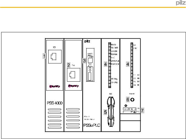
2.2Front view
MS
NS
Key:
}1: SafetyNET p interface
}2: SafetyNET p interface
}3: Labelling strip (see below for details)
}4: Status LEDs
}5: SD card
}6: Reset button
}7: Supply voltage connection (module and periphery supply)
The labelling strip contains the following information:
|
|
|
|
|
|
|
|
|
|
|
|
|
|
|
|
|
Order number |
|
|
312070 |
|
|
|||||||||
|
|
|
|
||||||||||||
|
Serial number |
|
|
100017 |
|
|
|||||||||
|
|
|
|
||||||||||||
|
Hardware version |
|
|
HW 001 |
|
||||||||||
|
|
|
|||||||||||||
|
2D code: |
|
|
|
|
|
|
|
|
|
|
|
|||
|
|
|
|
|
|
|
|
|
|
|
|
|
|
|
|
|
|
|
|
|
|
|
|
|
|
|
|
||||
|
Product |
|
|
|
|
|
|
|
|
||||||
|
information |
|
|
|
|
|
|
|
|
||||||
|
|
|
|
|
|
|
|
|
|||||||
|
|
|
|
|
|
|
|
|
|
MAC |
|
|
|||
|
MAC address |
|
|
|
|
|
|
|
ADD |
|
|
||||
|
|
|
|
0002 |
|
|
|
||||||||
|
|
|
|
|
|
|
|||||||||
|
|
|
|
|
|
|
|
|
|
|
|
||||
|
|
|
|
|
|
|
|
|
4840 |
|
|
|
|||
|
|
|
|
|
|
|
|
|
3152 |
|
|
|
|||
|
2D code: |
|
|
|
|
|
|
|
|
|
|||||
|
|
|
|
|
|
|
|
|
|
|
|
|
|||
|
|
|
|
|
|
|
|
|
|
||||||
|
MAC address |
|
|
|
|
|
|
|
|
||||||
|
|
|
|
|
|
|
|
|
|
|
|
|
|
|
|
|
|
|
|
|
|
|
|
|
|
|
|
|
|
|
|
|
|
|
|
|
|
|
|
|
|
|
|
|
|
|
|
|
|
|
|
|
|
|
|
|
|
|
|
|
|
|
|
|
|
|
|
|
|
|
|
|
|
|
|
|
|
|
|
Operating Manual PSSu H PLC1 FS SN SD(T)(R) |
8 |
21939EN10 |
|

Safety
3 Safety
3.1Intended use
The module is suitable for use in safety and nonsafetyrelated applications, with and without SafetyNET p.
The modules PSSu H PLC1 FS SN SD and PSSu H PLC1 FS SN SDT may be used as a safety component in accordance with the Lifts Directive 95/16/EC, EN 811, EN 812 and EN 1151.
The programmable safety system should be installed in a protected environment that meets at least the requirements of pollution degree 2. Example: Protected inside space or control cabinet with protection class IP54 and corresponding air conditioning.
The module PSSu H PLC1 FS SN SDT is suitable for use where there are increased envir onmental requirements (see Technical Details).
The module PSSu H PLC1 FS SN SDR is suitable for use where there are increased en vironmental requirements demanded by railway applications (see Technical Details).
Intended use includes making the electrical installation EMCcompliant. Please refer to the guidelines stated in the "PSSuniversal Installation Manual". The module is designed for use in an industrial environment. It is not suitable for use in a domestic environment, as this can lead to interference.
The following is deemed improper use in particular:
}Any component, technical or electrical modification to the module
}Use of the module outside the areas described in this manual
}Any use of the module that is not in accordance with the technical details.
NOTICE
Always use the latest version of PAS4000 for programming the head mod ules (download from www.pilz.de).
–Base type and Ttype: at least version 1.3.1.
–Rtype:
at least version 1.5.0
3.2Safety regulations
3.2.1Use of qualified personnel
The products may only be assembled, installed, programmed, commissioned, operated, maintained and decommissioned by competent persons.
Operating Manual PSSu H PLC1 FS SN SD(T)(R) |
9 |
21939EN10 |
|

Safety
A competent person is someone who, because of their training, experience and current pro fessional activity, has the specialist knowledge required to test, assess and operate the work equipment, devices, systems, plant and machinery in accordance with the general standards and guidelines for safety technology.
It is the company’s responsibility only to employ personnel who:
}Are familiar with the basic regulations concerning health and safety / accident preven tion
}Have read and understood the information provided in this description under "Safety"
}And have a good knowledge of the generic and specialist standards applicable to the specific application.
3.2.2Warranty and liability
All claims to warranty and liability will be rendered invalid if
}The product was used contrary to the purpose for which it is intended
}Damage can be attributed to not having followed the guidelines in the manual
}Operating personnel are not suitably qualified
}Any type of modification has been made (e.g. exchanging components on the PCB boards, soldering work etc.).
3.2.3Disposal
}In safetyrelated applications, please comply with the mission time tM in the safetyre lated characteristic data.
}When decommissioning, please comply with local regulations regarding the disposal of electronic devices (e.g. Electrical and Electronic Equipment Act).
Operating Manual PSSu H PLC1 FS SN SD(T)(R) |
10 |
21939EN10 |
|
Function description
4 |
Function description |
4.1Module features
4.1.1Control system
The head module is a programmable logic controller (PLC), which can be used in safetyre lated and nonsafetyrelated applications. The control system has memory areas for the op erating system, the data and the device project with the user program.
The head module has a nonvolatile memory for the nonvolatile variables.
User programs can be created in IEC 61131 programming and/or Multi programming.
For safetyrelated applications, the processor section is designed with multichannel di versity.
The control system communicates with the input and output modules via the local module bus and with the decentralised input and output modules via SafetyNET p. LEDs provide in formation on the status of the safety system and indicate any errors.
4.1.2Supply voltage
4.1.2.1Function description
The product provides the module supply and periphery supply for the modules on the mod ule bus:
}Module supply
Supply voltage for subsequent module (righthand side)
}Periphery supply
Supply voltage for sensors, actuators and test pulses
When the supply voltage is fed in separately, the module supply and periphery supply are galvanically isolated. If galvanic isolation is not required, a common power supply may be used for the periphery supply and module supply.
4.1.2.2Current load capacity
Ensure you comply with the current load capacity of the module and periphery supply (see "Technical Details"). If the current load is higher, an additional supply voltage module is re quired to refresh the module supply and periphery supply.
}Module supply
The current load is the total current consumption of all the electronic and compact mod ules.
The module supply does not automatically switch off if values exceed or drop below their limits. However, the "5 V" LED will light and a message will be entered in the dia gnostic list.
}Periphery supply
The current load is the total current consumption of the sensors, actuators and test pulses supplied via the input/output modules.
Operating Manual PSSu H PLC1 FS SN SD(T)(R) |
11 |
21939EN10 |
|

Function description
The periphery supply does not automatically switch off if values exceed or drop below their limits. However, the "24 V" LED will light and a message will be entered in the dia gnostic list.
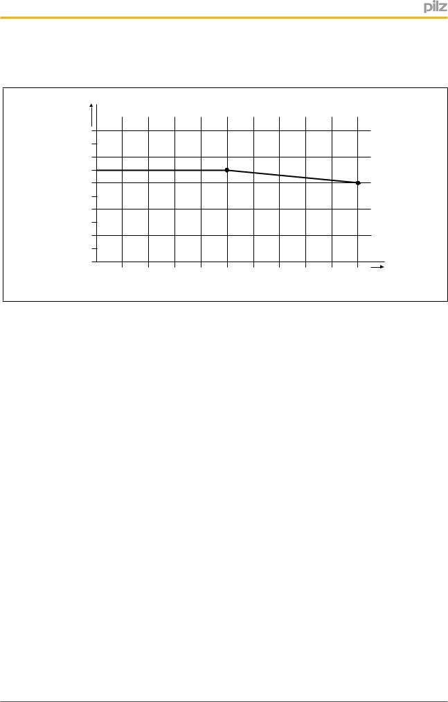
Please refer to the derating diagrams.
PSSu H PLC1 FS SN SD: Derating diagram for periphery supply: Temperature T depend ent on load current I
T (°C) |
|
|
|
|
|
|
|
|
|
|
100 |
|
|
|
|
|
|
|
|
|
|
80 |
|
|
|
|
|
|
|
|
|
|
60 |
|
|
|
|
|
|
|
|
|
|
40 |
|
|
|
|
|
|
|
|
|
|
20 |
|
|
|
|
|
|
|
|
|
|
0 |
|
|
|
|
|
|
|
|
|
|
1 |
2 |
3 |
4 |
5 |
6 |
7 |
8 |
9 |
10 |
I (A) |
PSSu H PLC1 FS SN SD (T)(R): Derating diagram for periphery supply: Permitted ambi ent temperature T dependent on load current I
T [°C] |
|
|
|
|
|
|
|
|
|
|
100 |
|
|
|
|
|
|
|
|
|
|
80 |
|
|
|
|
|
|
|
|
|
|
60 |
|
|
|
|
|
|
|
|
|
|
40 |
|
|
|
|
|
|
|
|
|
|
20 |
|
|
|
|
|
|
|
|
|
|
0 |
|
|
|
|
|
|
|
|
|
|
1 |
2 |
3 |
4 |
5 |
6 |
7 |
8 |
9 |
10 |
I [A] |
|
Operating Manual PSSu H PLC1 FS SN SD(T)(R) |
12 |
21939EN10 |
|
Function description
PSSu H PLC1 FS SN SD (T)(R): Derating diagram for infeed for module supply: Permitted ambient temperature T dependent on load current I
T [°C] |
|
|
|
|
|
|
|
|
|
|
100 |
|
|
|
|
|
|
|
|
|
|
80 |
|
|
|
|
|
|
|
|
|
|
60 |
|
|
|
|
|
|
|
|
|
|
40 |
|
|
|
|
|
|
|
|
|
|
20 |
|
|
|
|
|
|
|
|
|
|
0 |
|
|
|
|
|
|
|
|
|
|
0,2 |
0,4 |
0,6 |
0,8 |
1 |
1,2 |
1,4 |
1,6 |
1,8 |
2 |
I [A] |
|
4.1.3Integrated protection mechanisms
The module has the following protection mechanisms:
}Multichannel diverse processor section
}Cyclical self tests
}Potentially isolated SafetyNET p interface
}Infeed for module supply
–Polarity protection
–Voltage monitoring
–Transient voltage limitation
–20 ms voltage buffer if the supply voltage is interrupted
}Module supply
–Short circuitproof
}Periphery supply
–Voltage monitoring (exceeding upper/lower limit)
4.1.4SD card
The SD card has the following functions:
}The SD card is used to store the naming data and the device project; see PSS 4000 System Description.
}The SD card is part of the safety concept on PSS 4000. If the SD card is missing or has been swapped, the next time the PSSu system is booted it will be unable to achieve the operating status "PSSu System in RUN condition without error". The SD card has a
Operating Manual PSSu H PLC1 FS SN SD(T)(R) |
13 |
21939EN10 |
|
Loading...