


22 150-02
Betriebsanleitung
Operating Instructions
Instrucciones de uso
P3WP3P
Sicherheitsbestimmungen
• Das Gerät darf nur von Personen
installiert und in Betrieb genommen
werden, die mit dieser Betriebsanleitung
und den geltenden Vorschriften über
Arbeitssicherheit und Unfallverhütung
vertraut sind. Beachten Sie die VDEsowie die örtlichen Vorschriften, insbesondere hinsichtlich der Schutzmaßnahmen.
• Beim Transport, bei der Lagerung und im
Betrieb die Bedingungen nach EN 600682-6 einhalten (s. techn. Daten).
• Durch Öffnen des Gehäuses oder
eigenmächtige Umbauten erlischt die
Gewährleistung.
• Montieren Sie das Gerät in einen
Schaltschrank; Staub und Feuchtigkeit
können sonst zu Beeinträchtigungen der
Funktionen führen.
Bestimmungsgemäße Verwendung
Der Wirkleistungsmesswandler P3WP3P
dient in Überwachungsschaltungen als
Messeinrichtung für abgegebene Wirkleistung. Das Gerät kann drei Motoren, die am
Drehstromnetz betrieben werden, gleichzeitig messen. Zur Messauswertung wird ein
zusätzliches Auswertegerät benötigt (z. B.
Komparator, SPS, A/D-Wandler, Anzeigeinstrument o. ä.).
Safety Regulations
• The unit may only be installed and operated
by personnel who are familiar with both
these instructions and the current
regulations for safety at work and accident
prevention. Follow local regulations
especially as regards preventative
measures.
• Transport, storageand operating conditions
should all conform to
EN 60068-2-6.
• Any guarantee is void following opening of
the housing or unauthorised modifications.
• The unit should be panel mounted,
otherwise dampness or dust could lead to
functional impairment.
Intended Application
The True Power Monitor P3WP3P acts in
monitoring systems as measuring equipment
for true output power. The unit can
simultaneously measure three motors which
are driven on a three-phase current circuit.
To evaluate this an additional evaluating
unit is required (i.e. comparator, A/D
convertor etc.).
Normas de seguridad
• El dispositivo tiene que ser instalado y
puesto en funcionamiento exclusivamente
por personas que estén familiarizadas tanto
con estas instrucciones de uso como con
las prescripciones vigentes relativas a la
seguridad en el trabajo y a la prevención de
accidentes. Hay que observar tanto las
prescripciones VDE como las
prescripciones locales, especialmente en lo
que se refiere a las medidas de protección.
• Para el transporte, el almacenaje y el
funcionamiento, respetar los requisitos
establecidos en la norma EN 60068-2-6
(ver datos técnicos).
• Se pierde toda garantía en caso de que se
abra la carcasa o se lleven a cabo
modificaciones por cuenta propia.
• Montar el dispositivo dentro de un armario
de distribución; en caso contrario es
posible que el polvo y la suciedad puedan
afectar el funcionamiento.
Campo de aplicación adecuado
El conversor de medición de potencia activa
P3WP3P es un dispositivo de medida de la
potencia activa producida en circuitos de
supervisión. El dispositivo puede medir
simultáneamente tres motores conectados
a la red trifásica. Para evaluar la medición
se necesita un dispositivo de evaluación
suplementario (p. ej., comparador, PLC,
convertidor A/D, instrumento indicador o
similar).
Gerätebeschreibung
Der Wirkleistungsmesswandler P3WP3P
ist in einem P-01-90-mm-Gehäuse untergebracht.
Merkmale:
• Das Gerät P3WP3P wird über die
Klemmen +24V und GND versorgt.
• Die drei Außenleiter an den Klemmen
L11, L21 und L31 dienen als
Versorgungsspannung des ersten
Motors M1.
• Die drei Außenleiter an den Klemmen
L12, L22 und L32 dienen als
Messspannung des zweiten und dritten
Motors (M2, M3).
• LED als Versorgungsspannungsanzeige
• verschiedene Messbereiche für jedes
Messobjekt getrennt einstellbar
• Analogausgänge für Spannung
• Aronschaltung
Description
The true power monitor P3WP3P is enclosed
in a P-01, 90 mm housing.
Features:
• The internal voltage for the P3WP3P is
supplied via the terminals +24V and GND.
• The 3 external conductors at the terminals
L11, L21 and L31 function as the operating
voltage for the first motor (M1).
• The three external conductors at the
terminals L12, L22 and L32 function as the
measuring voltage for the second and
third motors (M2, M3).
• LED for operating voltage status indication
• Different adjustable measuring ranges can
be set individually for each object to be
measured
• Analogue outputs for voltage
• Aron wiring principle
Descripción del dispositivo
El conversor de medición de potencia activa
P3WP3P está dentro de una carcasa
P-01-90-mm.
Características:
• El dispositivo P3WP3P se alimenta a
través de los bornes +24V y GND.
• Los tres conductores de fase de los bornes
L11, L21 y L31 conducen la tensión de
alimentación del primer motor M1.
• Los tres conductores de fase de los
bornes L12, L22 y L32 conducen la
tensión de medición del segundo y tercer
motor (M2, M3).
• LED como indicador de la tensión de
alimentación
• Opción de ajustar diferentes intervalos de
medición para cada objeto
• Salidas analógicas para tensión
• Circuito Aron
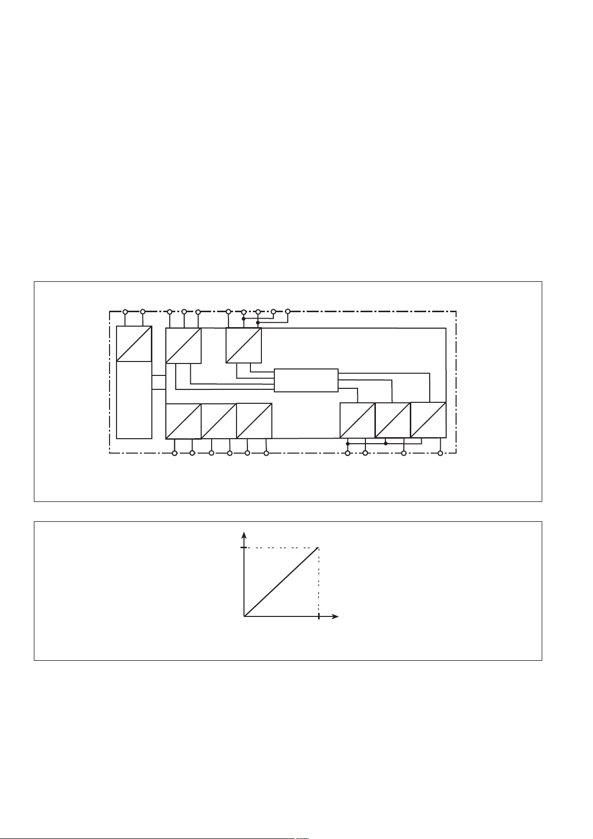
Funktionsbeschreibung
Der Wirkleistungsmesswandler P3WP3P
überträgt die aufgenommene Wirkleistung
eines Motors in ein elektrisches Ausgangssignal. Dazu wird der Laststrom IM und die
Messspannung gemessen. Aus Laststrom
und der Messspannung ermittelt der
Messwandler den Leistungsfaktor cos ϕ.
Durch Multiplikation von Spannung, Strom
und dem Leistungsfaktor bildet der
Messwandler ein zur
Wirkleistung proportionales Ausgangsignal.
Das Gerät arbeitet nach dem Prinzip der
Aronschaltung: Es wird für das erste
Messobjekt (M1) die Drehstromspannung an
den Klemmen L11, L21, L31 gemessen und
für das zweite und dritte Messobjekt (M2, M3)
die Drehstromspannung an den Klemmen
L12, L22, L32 gemessen. Für jedes der
Messobjekte werden 2 Phasenströme
getrennt gemessen. Das Ausgangsignal steht
als Spannungsausgang UA zur Verfügung. Zur
weiteren Signalverarbeitung ist ein zusätzliches Auswertegerät erforderlich.
+24V
GND
L11 L21 L31 L12 L22 L32 L22 L32
Function Description
The True Power Monitor P3WP3P forms a
measuring system which evaluates the
true absorbed power of a motor and
converts it to an analogue output signal.
The load current IM and the measuring
voltage are also measured. From the load
current and the measuring voltage, the unit
determines the power factor cos ϕ. By
multiplying the voltage, current and the
power factor the true power is determined,
and an output signal is produced proportional to this. The P1WP3/3 operates with Aron
wiring principle.
The 3-phase voltage at the terminals L11,
L21 and L31 is measured for the first
measured load (M1); for the second and third
measured loads (M2, M3), the
3-phase voltage is measured at terminals
L12, L22 and L32. Two phase currents are
measured separately for each measured load.
The output signal is available as voltage
output U
additional unit is required.
For further signal processing an
A.
Descripción del funcionamiento
El convertidorde potencia activa P3WP3P
transforma la potencia activa consumida de
un motor en una señal de salida eléctrica.
Para esto mide la corriente de carga IM y la
tensión de medición. Con la corriente de
carga y la tensión de medición, el conversor
determina el factor de potencia cos ϕ. El
conversor multiplica la tensión, la corriente y
el factor de potencia para generar una señal
de salida proporcional a la potencia activa. El
dispositivo trabaja según el principio de
conexión Aron: la tensión trifásica del primer
objeto (M1) se mide en los bornes L11, L21,
L31 y la tensión trifásica del segundo y
tercer objeto (M2, M3) se mide en los
bornes L12, L22, L32. Se miden 2
corrientes de fase por separado para cada
objeto de medida. La señal de salida se envía
a la salida de tensión UA. Para procesar la
señal se precisa un dispositivo de
evaluación.
=
U
M
I
M
U
M
I
M
=
U
Power
Power
I
Output
V1 W1
I
M
M
Output
V2 W2 V3 W3
I
Output
M
Fig. 1: Schematisches Schaltbild/Wiring diagram/Plano de conexiones esquemático
10 V
U
0 V
M * IM *
cos phi
P
max
P
A1
U
A
GND AN1
P
W
P
A1
U
A
AN2 AN3
P
A1
U
A
Fig. 2: Funktionsdiagramm/Timing diagram/Diagrama funcional

Montage
Das Gerät muss in einen Schaltschrank mit
einer Schutzart von min. IP 54 eingebaut
werden. Zur Befestigung auf einer Normschiene hat das Gerät ein Rastelement auf
der Rückseite.
Installation
The unit must be panel mounted (min. IP 54).
There is a notch on the rear of the unit for
DIN-Rail attachment.
Montaje
El dispositivo tiene que ser montado dentro
de un armario de distribución con un grado de
protección de IP 54 como mínimo. El
dispositivo dispone en su parte trasera de
un elemento de encaje para fijarlo a una
guía normalizada.
Inbetriebnahme
Beachten Sie bei der Inbetriebnahme:
• Die Messausgänge sind empfindlich. Um
Fehlfunktionen zu vermeiden, empfehlen
wir die Verwendung von abgeschirmten
Leitungen.
• Leitungsmaterial aus Kupferdraht mit einer
Temperaturbeständigkeit von 60/75 °C
verwenden.
• Das Anzugsdrehmoment der Schrauben auf
den Anschlussklemmen darf max.
0,6 Nm betragen.
• Achten Sie bitte auf eine sorgfältige Leitungsverlegung, da eine Unterbrechung im
Messkreis zum Ausfall der Gerätefunktion
führt.
• Angaben im Kapitel "Technische Daten"
unbedingt einhalten.
Hinweis!
• Sorgen Sie für eine ausreichende Absicherung der Anschlussleitungen
• P3WP3P liefert bei einem Ausfall der
Versorgungsspannungen an den Klemmen
+24V und GND an allen Spannungsausgängen 0 V, obwohl die angeschlossenen Motoren noch im Betrieb sind.
• Die Versorgungsspannung und der
Messstrom müssen für jeden Motor
phasenrichtig angeschlossen werden.
Commissioning
Please note when commissionng:
• The measuring outputs are very sensitive.
To avoid any malfunctions, we recommend
you use screened cables
• Use copper wiring that can withstand
60/75 °C.
• Tighten terminals to 0.6 Nm.
• Ensure adequate cabling and correct
connections, as an interruption on the
measuring circuit may lead to the unit
malfunctioning
• Important details in the section "Technical
Data" should be noted and adhered to.
Important!
• Ensure adequate fusing for the connection
cables
• If the operating voltages fail at terminals
+24V and GND, P3WP3P supplies 0 V on
all voltage outputs, although the
connected motors are still in operation
• The operating voltage and the measuring
current for each motor must be
connected in-phase.
Puesta en marcha
Al poner en marcha hay que tener en
cuenta:
• Las salidas de medición son sensibles.
Recomendamos utilizar cables
apantallados para evitar fallos de
funcionamiento.
• Utilizar cables de alambre de cobre con
una resistencia a la temperatura de
60/75 °C.
• El par de apriete de los tornillos en los
bornes de conexión puede ser de 0,6 Nm
como máximo.
• Extremar las precauciones a la hora de
instalar los cables, pues toda interrupción
del circuito de medición provocará un fallo
de funcionamiento del dispositivo.
• Respetar al pie de la letra las indicaciones
del capítulo "Datos técnicos".
Advertencia
• Comprobar que los cables de conexión
tengan protección suficiente.
• Si caen las tensiones de alimentación en
los bornes +24V y GND, el P3WP3P
transmite 0 V a todas las salida de tensión
aunque funcionen todavía los motores
conectados.
• Conectar correctamente las fases de la
tensión de alimentación y la corriente de
medición de cada motor.
Anschluss
• Schließen Sie ausschließlich die beschrifteten Klemmen an.
• Messkreis für Drehstromspannungen
(Messspannung):
erster Motor (M1): Phase L1 an Klemme
L11, Phase L2 an Klemme L21 und
Phase L3 an Klemme L31;
zweiter und dritter Motor (M2, M3): Phase
L1 an Klemme L12, Phase L2 an Klemme
L22 und Phase L3 an Klemme L32
Hinweis!
Bei einer Messpannung von 230 V müssen
die Klemmen L22-L22 und L32-L32
gebrückt werden.
• Messkreis für Phasenströme:
- ersten Motor an die mit "M1"
zusammengefassten Klemmen
anschließen:
Motorphase U an Klemme U1, Motorphase V an Klemme V1 und Motorphase
W an Klemme W1 anschließen.
- zweiten Motor wie zuvor beschrieben
an die unter "M2" zusammengefassten
Klemmen anschließen.
- dritten Motor wie zuvor beschrieben an
die unter "M3" zusammengefaßten
Klemmen anschließen.
• Nachfolgende Auswerteeinrichtung (z. B.
Komparator) an die Klemmen AN1 ... AN3
und GND anschließen.
Connection
• Only connect the labelled terminals.
• Measuring circuit for 3-phase voltages
(measuring voltage):
First motor (M1): phase L1 to terminal
L11, phase L2 to terminal L21 and phase
L3 to terminal L31. Second and third
motor (M2, M3): phase L1 to terminal
L12, phase L2 to terminal L22 and phase
L3 to terminal L32.
Important!
At a measuring voltage of 230 V, the
terminals L22-L22 and L32-L32 must be
linked.
• Measuring circuit for phase currents:
- connect the first motor to the combined
terminals of “M1”:
motor phase U to the terminal U1, motor
phase V to the terminal V1 and motor
phase W to the terminal W1
- connect the second motor as
described above, but on the “M2”
terminals
- connect the third motor as
described above, but on the “M3”
terminals
• Further measuring equipment (i.e.
comparator) connect on the terminals AN1
... AN3 and GND.
Conexión
• Conectar exclusivamente los bornes
rotulados.
• Circuito de medición de tensiones trifásicas
(tensión de medición):
primer motor (M1): fase L1 a borne L11,
fase L2 a borne L21 y fase L3 a borne
L31;
segundo y tercer motor (M2, M3): fase
L1 a borne L12, fase L2 a borne L22 y
fase L3 a borne L32.
Advertencia
Si la tensión de medición es de 230 V,
deben puentearse los bornes L22-L22 y
L32-L32.
• Circuito de medición de corrientes de fase:
- Conectar primer motor a los bornes
agrupados como "M1":
Conectar fase de motor U a borne U1,
fase de motor V a borne V1 y fase de
motor W a borne W1.
- Conectar segundo motor los bornes
agrupados como "M2" según se ha
descrito arriba.
- Conectar tercer motor a los bornes
agrupados como "M3" según se ha
descrito arriba.
• Conectar el dispositivo de evaluación
siguiente (p. ej., comparador) a los bornes
AN1 ... AN3 y GND.
Einstellung
• Gewünschten Messbereich am Drehschalter "M1" für das erste Messobjekt,
"M2" für das zweite Messobjekt und "M3"
für das dritte Messobjekt einstellen.
Setting
• Set required measuring range on the rotary
switch "M1" for the first measuring object,
“M2” for the second and “M3” for the
third.
Ajuste
• Ajustar el intervalo de medición elegido
mediante el mando "M1" para el primer
objeto, "M2" para el segundo objeto y "M3"
para el tercer objeto de medida.

Ablauf
Die LED "POWER" leuchtet, sobald die
Versorgungsspannung eingeschaltet wird.
Die Spannungsausgänge werden für alle 3
Messobjekte gleichzeitig aktiviert.
To operate
The LED "POWER" is illuminated when the
operating voltage (control voltage) is
applied. The voltage output for all three
measuring objects are activated.
Secuencia
En cuanto se conecta la tensión de
alimentación, se enciende el LED verde
"POWER". Las salidas de tensión se
activan simultáneamente para los 3 objetos
de medida.
Anwendung
Die nachfolgenden Schaltungsbeispiele sind
typische Anwendungen (Fig. 3).
L1
L2
L3
K2
M2
U
V
M 3~
V
W
M1
K1
U
M 3~
Application
The following circuit diagrams are typical
applications (Fig. 3).
L11
L21
M1
M1
V1W1V2
L31
M2
L12 L22
W2 V3
L32
M2 + M3
M3
W3
L22 L32
Aplicación
Los ejemplos de circuitos siguientes son
aplicaciones típicas (fig. 3).
Supply
GND
+24 V
GND
+24V
GND AN1AN2
GND I1 I2
AN3
I3
PLC
K3
V
U
W
M3
M 3~
W
N
Fig. 3: Messung von 3 Drehstrommotoren/Measurement from 3 rotary current motors/Medición de 3 motores trifásicos
L1
L2
L3
L11
L21
M1
L31
L12 L22
L32
M2 + M3
K4K3
L22 L32
Supply
GND
GND
P3WP3P
M2
W2 V3
M3
W3
GND AN1AN2
GND I1 I2
PLC
M1
V1W1V2
K2K1
+24 V
+24V
AN3
I3
M1
U
V
M 3~
V
U
W
M2
M 3~
W
M3
U
V
M 3~
W
N
Fig. 4: Messung von 3 Drehstrommotoren mit Drehrichtungsumkehr/Measurement of three 3-phase motors with a change in
phase rotation/Medición de 3 motores trifásicos con inversión de dirección de giro

Technische Daten/Technical Data/Datos técnicos
Elektrische Anforderungen/Electrical Data/Requisitos eléctricos
Versorgungsspannung UB/Operating Voltage UB/Tensión de alimentación U
Spannungstoleranz UB/Voltage Tolerance UB /Tolerancia de tensión de alimentación U
Leistungsaufnahme bei UB/Power Consumption at UB/Consumo de energía con U
Messspannung UM/Measuring Voltage UM/Tensión de medición U
M
Spannungstoleranz UM/Voltage Tolerance UM /Tolerancia de tensión U
Frequenzbereich UM/Frequency Range UM/Margen de frecuencia U
B
B
B
M
M
Eigenschaften/Features/Propiedades
Abweichung von UA bei Temperaturänderung/Deviation UA at Temperature change/ ± 0,1%/K
Diferencia respecto a UA con variación de temperatura (bei/at/con cos ϕ = 0,87)
Reaktionszeit (bezogen auf 63 % ΔUA)/Reaction time (refers to 63 % ΔUA)/ ca./appx./aprox. 30 ms
Tiempo de reacción (referido a 63% ΔUA)
Ausgangssignale bei Motorbetrieb/Output signal with motor drive/
Señales de salida con motor en funcionamiento:
Ausgangsspannung UA /Output Voltage UA /Tensión de salida U
A
Abschlussimpedanz RA (Bürde)/Terminating Impedance RA/Impedancia de terminación RA (carga) ≥ 1 kΩ
Restwelligkeit UA/Residual Ripple UA/Ondulación residual U
A
Grenzbelastbarkeit/Loading capacity limit/Capacidad de carga límite
Max. zulässige Überlastung Messkreis/Max. permitted overload on measure circuit/ UM = 230 V: 6 A (100 %); 12 A (max./máx. 5 s)
Sobrecarga máx. permitida circuito medición UM = 400 V: 3,5 A (100 %); 7 A (max./máx. 5 s)
Elektromagnetische Verträglichkeit (EMV)/Electromagnetic Compatibility (EMC)/ EN 61000-6-2, EN 61000-6-4
Compatibilidad electromagnética (CEM)
Luft- und Kriechstrecken nach/Airgap Creepage/Distancias de fuga y dispersión superficial según EN 60947-1
Geräteabsicherung min. 1 A; max. abhängig vom Leitungsquerschnitt
Unit Fuse Protection min. 1 A; max. dependent on cable cross section
Protección de dispositivo mín. 1 A; máx. en función de la sección del cable
Umgebungsbedingungen/Environment Conditions/Condiciones ambientales
Umgebungstemperatur/Operating Temperature/Temperatura ambiente 0 ... +60 °C
Lagertemperatur/Storage Temperature/Temperatura de almacenamiento -40 ... +85 °C
Klimabeanspruchung/Climate Suitability/Condiciones ambientales EN 60068-2-6
Schwingungen nach/Vibration to/Oscilaciones según IEC 68-2-6 Frequenz/Frequency/Frecuencia: 10...55 Hz
Allgemeine Angaben zum Gerät/General Information - Unit/
Datos generales del dispositivo
Max. Anschlussquerschnitt (Einzelleiter und mehrdrähtiger Leiter mit Aderendhülsen) 1 x 2,5 mm² oder/or/o 2 x 1,5 mm2
Max. cable cross section (single-core or multicore with crimpconnectors)
Sección de conexión máx. (conductor monofilar y conductor multifilar con terminales)
Anzugsdrehmoment für Anschlussklemmen (Schrauben)/Torque setting for connection 0,6 Nm
terminal screws/Par de apriete de bornes de conexión (tornillos)
Schutzarten/Protection/Grados de protección:
Einbauraum (z. B. Schaltschrank)/Mounting (e.g. Panel)/
Lugar de montaje (p. ej., armario de distribución) IP 54
Gehäuse/Housing/Carcasa IP 20
Klemmenbereich/Terminals/Zona de bornes IP 20
Gehäusematerial (Kunststoff)/Housing material (synthetic)/Material de la carcasa (plástico) Noryl SE 100
Abmessungen (H x B x T)/Dimensions (H x W x D)/Dimensiones (Al x An x P) 94 x 90 x 121 mm (3.7" x 3.54" x 4.76")
Gewicht/Weight/Peso 470 g
+24 V DC
-15 %/+10 %
ca./appx./aprox. CC: 2,5 W
3 AC: 230 V, 400 V
85 - 110 %
50 ... 60 Hz
DC: 0 ... +10 V
max./máx. 100 mV
Amplitude/Amplitude/Amplitud: 0,35 mm
Es gelten die 2009-11 aktuellen Ausgaben der
Normen.
The standards current on 2009-11 apply
Son válidas las versiones actuales de las
normas 2009-11.
Range P[kw]
12345
230 V 1,5 2,1 2,7 3,3 3,9
400 V 1,5 2,1 2,7 3,3 3,9
Tab. 1: Einstellbare Messbereichsendwerte/Adjustable measuring ranges/Valores finales del intervalo de medición, ajustables

Abmessungen in mm ('')/Dimensions in mm ('')/Dimensiones en mm ('')
121 (4.76")
94 (3.70")
EG-Konformitätserklärung:
Diese(s) Produkt(e) erfüllen die Anforderungen der Richtlinie 2006/42/EG über
Maschinen des europäischen Parlaments
und des Rates.
Die vollständige EG-Konformitätserklärung
finden Sie im Internet unter www.pilz.com
Bevollmächtigter: Norbert Fröhlich,
Pilz GmbH & Co. KG, Felix-Wankel-Str. 2,
73760 Ostfildern, Deutschland
90 (3.54")
EC Declaration of Conformity:
This (these) product(s) comply with the
requirements of Directive 2006/42/EC of the
European Parliament and of the Council on
machinery.
The complete EC Declaration of Conformity
is available on the Internet at www.pilz.com
Authorised representative: Norbert Fröhlich,
Pilz GmbH & Co. KG, Felix-Wankel-Str. 2,
73760 Ostfildern, Germany
Déclaration de conformité CE :
Ce(s) produit(s) satisfait (satisfont) aux
exigences de la directive 2006/42/CE
relative aux machines du Parlement
Européen et du Conseil.
Vous trouverez la déclaration de conformité
CE complète sur notre site internet
www.pilz.com
Représentant : Norbert Fröhlich,
Pilz GmbH & Co. KG, Felix-Wankel-Str. 2,
73760 Ostfildern, Allemagne
Technischer Support
+49 711 3409-444 +49 711 3409-444
...
In vielen Ländern sind wir durch
unsere Tochtergesellschaften und
Handelspartner vertreten.
Nähere Informationen entnehmen
Sie bitte unserer Homepage oder
nehmen Sie Kontakt mit unserem
Stammhaus auf.
Technical support
... ...
In many countries we are
represented by our subsidiaries
and sales partners.
Please refer to our Homepage
for further details or contact our
headquarters.
Asistencia técnica
Assistance technique
+49 711 3409-444
Tenemos filiales y socios
Nos filiales et partenaires
comerciales que nos
commerciaux nous représentent
representan en muchos países.
dans plusieurs pays.
Para más información, visite
Pour plus de renseignements,
nuestra página web o contacte
consultez notre site internet ou
contactez notre maison mère.
con nuestra sede central.
www
www.pilz.com
Pilz GmbH & Co. KG
Sichere Automation
Felix-Wankel-Straße 2
73760 Ostfildern, Germany
Telephone: +49 711 3409-0
Telefax: +49 711 3409-133
E-Mail: pilz.gmbh@pilz.de
Originalbetriebsanleitung/Original instructions/Notice originale
22 150-02, 2010-12 Printed in Germany
 Loading...