


 Loading...
PNOZ s4
Safety relays
Operating Manual21396EN13
This document is a translation of the original document.
All rights to this documentation are reserved by Pilz GmbH & Co. KG. Copies may be made for internal purposes. Suggestions and comments for improving this documentation will be gratefully received.
Pilz®, PIT®, PMI®, PNOZ®, Primo®, PSEN®, PSS®, PVIS®, SafetyBUS p®, SafetyEYE®, SafetyNET p®, the spirit of safety® are registered and protected trademarks of Pilz GmbH & Co. KG in some countries.
 SD means Secure Digital

Content
Introduction |
4 |
Validity of documentation |
4 |
Retaining the documentation |
4 |
Definition of symbols |
4 |
|
|
PNOZ s4 safety relay |
5 |
|
|
For your safety |
5 |
|
|
Unit features |
5 |
|
|
Safety features |
6 |
|
|
Block diagram/terminal configuration |
6 |
|
|
Function description |
7 |
|
|
Installation |
7 |
|
|
Wiring |
8 |
|
|
Preparing for operation |
8 |
Operating modes |
8 |
Set operating modes |
8 |
Connection |
9 |
|
|
Operation |
11 |
Status indicators |
11 |
Error indicators |
11 |
|
|
Faults malfunctions |
13 |
|
|
Service life graph |
13 |
|
|
Technical details |
14 |
Safety characteristic data |
25 |
|
|
Order reference |
26 |
|
|
EC declaration of conformity |
26 |
Operating Manual PNOZ s4 |
3 |
21396EN13 |
|
PNOZ s4
Introduction
Validity of documentation
This documentation is valid for the product PNOZ s4. It is valid until new documentation is published.
This operating manual explains the function and operation, describes the installation and provides guidelines on how to connect the product.
Retaining the documentation
This documentation is intended for instruction and should be retained for future reference.
Definition of symbols
Information that is particularly important is identified as follows:
DANGER!
This warning must be heeded! It warns of a hazardous situation that poses an immediate threat of serious injury and death and indicates preventive measures that can be taken.
WARNING!
This warning must be heeded! It warns of a hazardous situation that could lead to serious injury and death and indicates preventive measures that can be taken.
CAUTION!
This refers to a hazard that can lead to a less serious or minor injury plus material damage, and also provides information on preventive measures that can be taken.
NOTICE
This describes a situation in which the product or devices could be dam aged and also provides information on preventive measures that can be taken. It also highlights areas within the text that are of particular import ance.
Operating Manual PNOZ s4 |
4 |
21396EN13 |
|

PNOZ s4
INFORMATION
This gives advice on applications and provides information on special fea tures.
PNOZ s4 safety relay
The safety relay provides a safetyrelated interruption of a safety circuit.
The safety relay meets the requirements of EN 6094751, EN 602041 and VDE 01131 and may be used in applications with
}ESTOP pushbuttons
}Safety gates
}Light beam devices
Units with the following order numbers can be used as a safety component for lifts in ac cordance with Annex IV of the directive 95/16/EC and EN 811:
}750 104
}751 104
}750 134
}751 134
For your safety
}Only install and commission the unit if you have read and understood these operating instructions and are familiar with the applicable regulations for health and safety at work and accident prevention.
Ensure VDE and local regulations are met, especially those relating to safety.
}Any guarantee is rendered invalid if the housing is opened or unauthorised modifica tions are carried out.
}With railway applications in accordance with EN 50155: The unit may only be access ible for maintenance and repair and not during operation.
Unit features
}Positiveguided relay outputs:
–2 safety contacts (N/O), instantaneous
–1 auxiliary contact (N/C), instantaneous
}1 semiconductor output
}Connection options for:
–ESTOP pushbutton
–Safety gate limit switch
–Start button
–Light beam device
–PSEN
Operating Manual PNOZ s4 |
5 |
21396EN13 |
|

PNOZ s4
}A connector can be used to connect 1 PNOZsigma contact expansion module
}Operating modes can be set via rotary switch
}LED indicator for:
–Supply voltage
–Input status, channel 1
–Input status, channel 2
–Switch status of the safety contacts
–Start circuit
–Errors
}Plugin connection terminals (either springloaded terminal or screw terminal)
Safety features
The relay meets the following safety requirements:
}The circuit is redundant with builtin selfmonitoring.
}The safety function remains effective in the case of a component failure.
}The correct opening and closing of the safety function relays is tested automatically in each onoff cycle.
}The unit has an electronic fuse.
Block diagram/terminal configuration
|
|
* |
|
|
|
|
* |
A1 |
A2 |
S11 S12 S21 S22 |
13 |
23 |
33 |
41 |
|
= |
) |
|
|
|
|
|
|
(~) |
|
Input |
Input |
|
|
|
|
|
|
|
|
|
|
||
( |
= |
|
|
K1 |
|
|
Interface expansion unit |
Power |
|
|
|
|
|
||
|
|
|
|
|
|
|
|
|
|
|
|
K2 |
|
|
|
|
|
Reset/ |
|
|
|
|
|
|
|
Start |
|
|
|
|
|
|
|
S34 |
Y32 |
14 |
24 |
34 |
42 |
Fig.: Rotary cam arrangement monitoring Front view with cover, right: Front view without cover
Grey highlighted area: Applies only with UB = 48 – 240 V AC/DC
*Insulation between the nonmarked area and the relay contacts: Basic insulation (over voltage category III), Protective separation (overvoltage category II)
Operating Manual PNOZ s4 |
6 |
21396EN13 |
|

PNOZ s4
Function description
}In2+ Singlechannel operation: no redundancy in the input circuit, earth faults in the start
circuit and input circuit are detected.
}Dualchannel operation without detection of shorts across contacts: redundant input cir cuit, detects
–earth faults in the start and input circuit,
–short circuits in the input circuit and, with a monitored start, in the start circuit too.
}In2- Dualchannel operation with detection of shorts across contacts: redundant input cir cuit, detects
–earth faults in the start and input circuit,
–short circuits in the input circuit and, with a monitored start, in the start circuit too,
–shorts between contacts in the input circuit.
} Automatic start: Unit is active once the input circuit has been closed.
}Manual start: Unit is active once the input circuit is closed and then the start circuit is closed.
} Monitored start with falling edge: Unit is active once
–the input circuit is closed and then the start circuit is closed and opened again.
–the start circuit is closed and then opened again once the input circuit is closed.
} Monitored start with rising edge: Unit is active once the input circuit is closed and once the start circuit is closed after the waiting period has elapsed (see technical de tails).
} Start with startup test: The unit checks whether safety gates that are closed are opened and then closed again when supply voltage is applied.
}Increase in the number of available instantaneous safety contacts by connecting con tact expander modules or external contactors/relays;
A connector can be used to connect 1 PNOZsigma contact expander module.
Installation
Install base unit without contact expansion module:
}Ensure that the plug terminator is inserted at the side of the unit.
Connect base unit and PNOZsigma contact expansion module:
}Remove the plug terminator at the side of the base unit and at the contact expansion module.
}Connect the base unit and the contact expansion module to the supplied connector be fore mounting the units to the DIN rail.
Installation in control cabinet
}The safety relay should be installed in a control cabinet with a protection type of at least IP54.
}Use the notch on the rear of the unit to attach it to a DIN rail (35 mm).
}When installed vertically: Secure the unit by using a fixing element (e.g. retaining bracket or end angle).
Operating Manual PNOZ s4 |
7 |
21396EN13 |
|

PNOZ s4
}Push the device upwards or downwards before lifting it from the DIN rail.
Wiring
Please note:
}Information given in the "Technical details" must be followed.
}Outputs 1314, 2324, 3334 are safety contacts; output 4142 is an auxiliary contact (e.g. for display).
}Auxiliary contact 4142 and semiconductor output Y32 should not be used for safety circuits!
}To prevent contact welding, a fuse should be connected before the output contacts (see technical details).
}Calculation of the max. cable length lmax in the input circuit:
Imax |
= |
Rlmax |
Rl / km |
Rlmax = max. overall cable resistance (see technical details)
Rl / km = cable resistance/km
}Use copper wire that can withstand 60/75 °C.
}Sufficient fuse protection must be provided on all output contacts with capacitive and in ductive loads.
}With UB 48 – 240 VAC/DC: Connect S21 to the protective earth system
}When connecting magnetically operated, reed proximity switches, ensure that the max. peak inrush current (on the input circuit) does not overload the proximity switch.
Preparing for operation
Operating modes
The operating mode is set via the rotary switch on the unit. You can do this by opening the cover on the front of the unit.
NOTICE
Do not adjust the rotary switch during operation, otherwise an error mes sage will appear, the safety contacts will open and the unit will not be ready for operation until the supply voltage has been switched off and then on again.
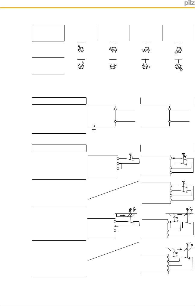
Set operating modes
}Switch off supply voltage.
}Select operating mode via the operating mode selector switch "mode".
}If the operating mode selector switch "mode" is in its start position (vertical position), an error message will appear.
Operating Manual PNOZ s4 |
8 |
21396EN13 |
|
PNOZ s4
Operating mode |
Automatic/ |
Monitored start |
Monitored start |
Automatic start |
selector switch |
manual start |
rising edge |
falling edge |
with startup test |
"mode" |
|
|
|
|
Without detec |
In2+ In2- |
In2+ In2- |
In2+ In2- |
In2+ In2- |
|
|
|
|
|
tion of shorts |
|
|
|
|
across contacts |
|
|
|
|
With detection of |
In2+ In2- |
In2+ In2- |
In2+ In2- |
In2+ In2- |
shorts across |
|
|
|
|
contacts |
|
|
|
|
Connection
}Supply voltage
Supply voltage |
AC |
|
|
DC |
|
|
|
A1 |
L |
A1 |
L+ |
|
S21 |
A2 |
N |
A2 |
L- |
|
|
|
}Input circuit
Input circuit |
Singlechannel |
Dualchannel |
|
|
ESTOP |
S1 |
|
S1 |
|
without detection of shorts |
S11 |
S11 |
|
|
S12 |
|
|
|
|
across contacts |
S22 |
S12 |
|
|
|
|
|
|
|
|
|
S22 |
|
|
ESTOP |
|
|
S1 |
|
with detection of shorts |
|
S11 |
|
|
|
S21 |
|
|
|
across contacts |
|
S22 |
|
|
|
|
S12 |
|
|
Safety gate |
|
|
|
|
without detection of shorts |
|
S1 |
|
|
across contacts |
|
|
|
|
S11 |
S11 |
S1 |
|
|
|
|
|
S2 |
|
|
S12 |
|
|
|
|
|
|
|
|
|
S22 |
S12 |
|
|
|
|
S22 |
|
|
Safety gate |
|
|
|
|
with detection of shorts |
|
|
|
|
across contacts |
|
S11 |
|
|
|
|
S1 |
|
|
|
|
|
S2 |
|
|
|
S12 |
|
|
|
|
|
|
|
|
|
S21 |
|
|
|
|
S22 |
|
|
Operating Manual PNOZ s4 |
9 |
21396EN13 |
|
Loading...