


PSEN-op4H-s-30-150-1
Table of contents
 Loading...
PSEN op4F/H-s-...../1
Safety light curtains with infrared beams
OPERATING MANUAL
1001422-EN-03

This document is a translation of the original document.
All rights to this documentation are reserved by Pilz GmbH &
Co. KG. Copies may be made for internal purposes.
Suggestions and comments for improving this documentation
will be gratefully received.
Pilz®, PIT®, PMI®, PNOZ®, Primo®, PSEN®, PSS®, PVIS®,
SafetyBUS p®, SafetyEYE®, SafetyNET p®, the spirit of
safety® are registered and protected trademarks of
Pilz GmbH & Co. KG in some countries.
Pilz GmbH & Co. KG
Felix-Wankel-Straße 2
73760 Ostfildern, Germany
Telephone: +49 711 3409-0
Telefax: +49 711 3409-133
E-Mail: pilz.gmbh@pilz.de
www.pilz.com

PSEN op4F/H-s Series Instruction Manual
INDEX
1. GENERAL INFORMATION .......................................................................................... 1
1.1. General Description of the safety light curtains ................................................... 1
1.1.1. Package contents ................................................................................... 3
1.2. New features compared PSEN op4F-s series (with EDM function) .................... 3
1.3. How to choose the device ................................................................................... 4
1.3.1. Resolution .............................................................................................. 4
1.3.2. Controlled height .................................................................................... 5
1.3.3. Minimum installation distance ................................................................ 6
1.4. Typical applications ............................................................................................. 8
1.5. Safety information ............................................................................................. 11
2. INSTALLATION MODE .............................................................................................. 12
2.1. Precautions to be observed for the choice and installation ............................... 12
2.2. General information on device positioning ........................................................ 13
2.2.1. Minimum installation distance .............................................................. 14
2.2.2. Minimum distance from reflecting surfaces .......................................... 15
2.2.3. Distance between homologous devices ............................................... 17
2.2.4. Emitter and receiver orientation ........................................................... 20
2.2.5. Use of deviating mirrors ....................................................................... 20
2.2.6. Controls after first installation ............................................................... 21
3. MECHANICAL MOUNTING ....................................................................................... 23
4. ELECTRICAL CONNECTIONS ................................................................................. 26
4.1. Notes on connections ........................................................................................ 28
4.2. Ground connection ............................................................................................ 31
5. ALIGNMENT PROCEDURE ...................................................................................... 33
5.1. Correct alignment procedure ............................................................................. 34
6. FUNCTIONING MODE ............................................................................................... 36
6.1. Restart mode ..................................................................................................... 36
6.2. Test function ...................................................................................................... 37
6.3. Reset function ................................................................................................... 37
6.4. EDM function ..................................................................................................... 38
6.5. Alignment aid function ....................................................................................... 39
7. DIAGNOSTIC FUNCTIONS ....................................................................................... 40
7.1. User interface .................................................................................................... 40
7.2. Dagnostic messages ......................................................................................... 41
8. PERIODICAL CHECKS ............................................................................................. 44
8.1. General information and useful data ................................................................. 45
9. DEVICE MAINTENANCE ........................................................................................... 46
9.1. Product disposal ................................................................................................ 46
10. TECHNICAL DATA .................................................................................................... 47
11. LIST OF AVAILABLE MODELS ................................................................................ 48
12. OVERALL DIMENSIONS ........................................................................................... 49
13. OUTFIT ....................................................................................................................... 50
14. ACCESSORIES .......................................................................................................... 51
14.1 Angled fixing bracket mounting ......................................................................... 52
15. GLOSSARY ................................................................................................................ 57


Instruction Manual PSEN op4F/H-s Series
1
1. GENERAL INFORMATION
1.1. General Description of the safety light curtains
The safety light curtains of the PSEN op4F/H-s series are
optoelectronic multibeam devices that are used to protect working
areas that, in presence of machines, robots, and automatic systems
in general, can become dangerous for operators that can get in
touch, even accidentally, with moving parts.
The light curtains of the PSEN op4F/H-s series are Type 4 intrinsic
safety systems used as accident-prevention protection devices and
are manufactured in accordance with the international Standards in
force for safety, in particular:
CEI IEC 61496-1: 2004 Safety of machinery: electrosensitive
protective equipment. Part 1:
General prescriptions and tests.
CEI IEC 61496-2: 2006 Safety of machinery: electrosensitive
protective equipment - Particular
requirements for equipment using
active optoelectronic protective
devices.
The device, consisting of one emitter and one receiver housed inside
strong aluminium profiles, generates infrared beams that detect any
opaque object positioned within the light curtain detection field.
The emitter and the receiver are equipped with the command and
control functions. The connections are made through a M12
connector located in the lower side of the profile.
The synchronisation between the emitter and the receiver takes
place optically, i.e. no electrical connection between the two units is
required.
The microprocessor guarantees the check and the management of
the beams that are sent and received through the units: The
microprocessor LEDs inform the operator about the general
conditions of the safety light curtain (see section 7 “Diagnostic
functions”).
PSEN op4F/H-s Series Instruction Manual
2
The device consists in 2 units that, according to the model, are
composed by one or several emitting and receiving modules. The
receiver checks the control operations and safety actions.
During installation, an user interface facilitates the alignment of both
units (see section 5 “Alignment procedure”).
As soon as an object, a limb or the operator’s body accidentally
interrupts one or some of the infrared beams sent by the emitter, the
receiver immediately opens the OSSD outputs and blocks the MPCE
machine (if correctly connected to the OSSD).
Some parts or sections of this manual containing important
information for the user or installing operator are preceded by a note:
Notes and detailed descriptions about particular characteristics of the
safety devices in order to better explain their functioning.
Special instructions regarding the installation process.
The information provided in the paragraphs following this symbol is
very important for safety and may prevent accidents.
Always read this information accurately and carefully follow the
advice to the letter.
This manual contains all the information necessary for the selection
and operation of the safety devices.
However, specialised knowledge not included in this technical
description is required for the planning and implementation of a
safety light curtain on a power-driven machine. As the required
knowledge may not be completely included in this manual, we
suggest the customer to contact Pilz Technical Service for any
necessary information relative to the functioning of the PSEN
op4F/H-s light curtains and the safety rules that regulate the correct
installation (see section 8 “Periodical checks”).

Instruction Manual PSEN op4F/H-s Series
3
1.1.1. Package contents
• Package contains the following objects:
• Receiver (RX)
• Emitter (TX)
• Installation Quick Guide of PSEN op4F/H-s curtain
• Biannual checklist and periodical maintenance schedule
• CD with instruction manual and other documents
• 4 angled fixing brackets and specific fasteners
• 2 angled fixing brackets for models with heights included between
1200 and 1800 mm
1.2. New features compared PSEN op4F-s series (with EDM function)
With respect to PSEN op4F-s (EDM) series, the PSEN op4F/H-s.../1
Series safety light curtain series presents new important features:
• Higher operating distance
• Shorter response time (see sect.10 “Technical Data”)
• Range enlargement with 150 to 1800 mm controlled heights
• New fastening system with rotating brackets
• TEST line with reversed activation logics (active high)
• Advanced alignment for receiver and transmitter units
Furthermore, PSEN op4F-s has 2 selectable functions, i.e.:
• EDM function
• Manual/automatic Restart
PSEN op4F/H-s Series Instruction Manual
4
1.3. How to choose the device
There are at least three different main characteristics that should be
considered when choosing a safety light curtain, after having
evaluated the risk assessment:
1.3.1. Resolution
The resolution of the device is the minimum dimension that an
opaque object must have in order to obscure at least one of the
beams that constitute the sensitive area.
The resolution strictly depends on the part of the body to be
protected.
R = 14mm Finger protection
Type 4
R = 30 mm Hand protection
Type 4
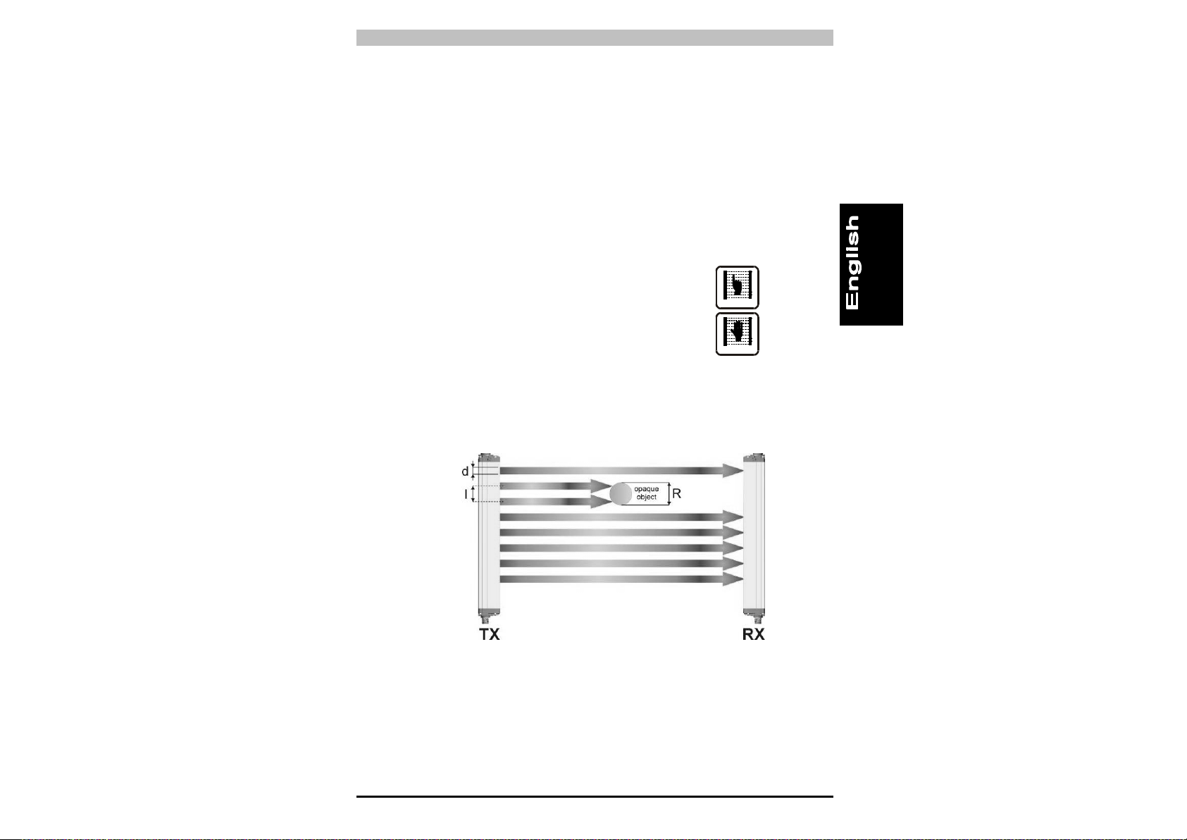
As shown in Fig.1, the resolution only depends on the geometrical
characteristics of the lenses, diameter and distance between centres,
and is independent of any environmental and operating conditions of
the safety light curtain.
Fig. 1
The resolution value is obtained applying the following formula:
R = I + d
where:
I = Distance between two adjacent optics
d = Lens diameter
Instruction Manual PSEN op4F/H-s Series
5
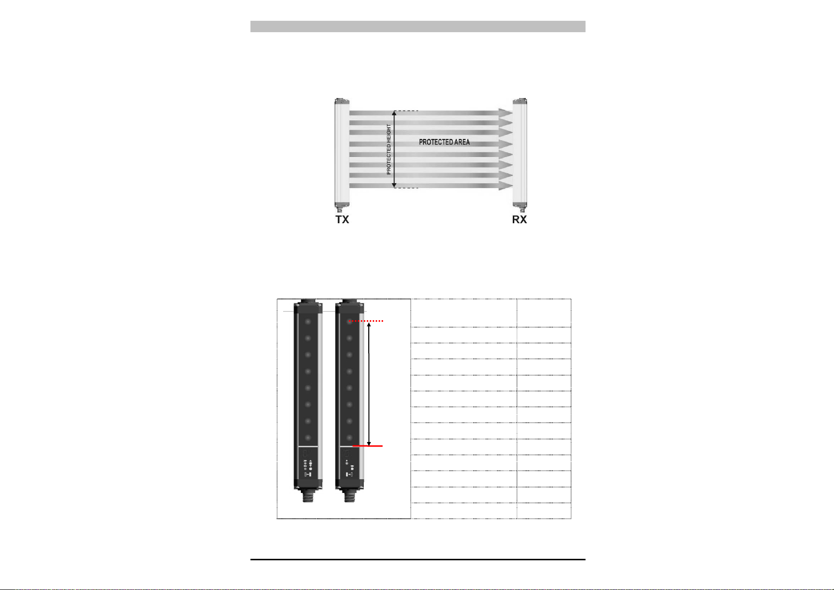
1.3.2. Controlled height
The controlled height is the height protected by the safety light
curtain (Hp)
Fig. 2
The PSEN op4F/H-s controlled height is delimited by the yellow line
pad-printed on the front glass and by the dimensions listed in the
table:
Model
Controlled
height Hp
(mm)
PSEN op4F/H-s-XX-015/1 150
PSEN op4F/H-s-XX-030/1 300
PSEN op4F/H-s-XX-045/1 450
PSEN op4F/H-s-XX-060/1 600
PSEN op4F/H-s-XX-075/1 750
PSEN op4F/H-s-XX-090/1 900
PSEN op4F/H-s-XX-105/1 1050
PSEN op4F/H-s-XX-120/1 1200
PSEN op4F/H-s-XX-135/1 1350
PSEN op4F/H-s-XX-150/1 1500
PSEN op4F/H-s-XX-165/1 1650
PSEN op4F/H-s-XX-180/1 1800
xx = Resolution (14 mm – 30 mm)
Hp
Reference

PSEN op4F/H-s Series Instruction Manual
6
1.3.3. Minimum installation distance
The safety device must be positioned at a specific safety distance
(Fig. 3). This distance must ensure that the dangerous area cannot
be reached before the dangerous motion of the machine has been
stopped by the AOPD.
The safety distance depends on 4 factors, according to the EN-999
Standard:
• Response time of the AOPD (the time between the effective beam
interruption and the opening of the OSSD contacts).
• Machine stopping time (the time between the effective opening of
the contacts of the AOPD and the real stop of the dangerous
motion of the machine).
• AOPD resolution.
• Approaching speed of the object to be detected.
Fig. 3
The following formula is used for the calculation of the safety
distance:
S = K (t
1
+ t
2
) + C
where:
S = Minimum safety distance in mm.
K = Speed of the object, limb or body approaching the
dangerous area in mm/sec.
t
1
= Response time of the AOPD in seconds
(see section 10 “Technical data”)
t
2
= Machine stopping time in seconds.
d = Resolution of the system.
C = Additional distance based on the possibility to insert the body or one
of body parts inside the dangerous area before the protective
device trips.
C = 8 (d -14) for devices with resolution ≤ 40 mm.
Instruction Manual PSEN op4F/H-s Series
7
NOTE: K value is:
2000 mm/s if the calculated value of S is ≤ 500 mm
1600 mm/s if the calculated value of S is > 500 mm
When devices with > 40 mm resolution are used, the height of the top
beam has to be ≥ 900 mm (H2) from machine supporting base while
the height of the bottom beam has to be ≤ 300 mm (H1).
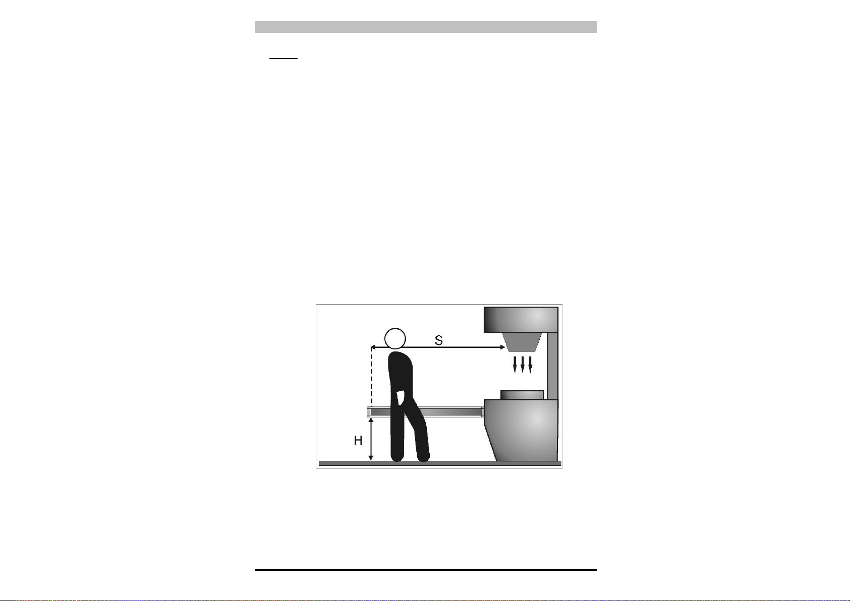
If the safety light curtain must be mounted in a horizontal position
(Fig.4), the distance between the dangerous area and the most
distant optical beam must be equal to the value calculated using the
following formula:
S = 1600 mm/s (t
1
+ t
2
) + 1200 – 0.4 H
where:
S = Minimum safety distance in mm.
t
1
= Response time of the AOPD in seconds
(see section 10 “Technical data”)
t
2
= Machine stopping time in seconds.
H = Beam height from ground. This height must always be less than
1,000 mm.
Fig. 4
PSEN op4F/H-s Series Instruction Manual
8
Practical examples
Let's suppose to have a light curtain with height = 600 mm
To calculate the distance of the device from the AOPD, in a
vertical
position, the following formula is used:
S = K*T + C
where:
T = t
1
+ t
2
t
1
= AOPD response time + PNOZsigma relay release time (max 80 ms)
t
2
= Machine total stopping time.
C = 8 * (d – 14) for devices with resolution <= 40 mm
D = resolution
In all cases, if K = 2000mm/sec then S > 500 mm. Distance will have
then to be recalculated using K = 1600 mm/sec.
PSEN op4F-s-14-060/1 PSEN op4H-s-30-060/1
T
0.393 sec
0.394 sec
C
0 mm 128 mm
S
641.6 mm 758.4 mm
WARNING: The reference standard is EN 999 “Machine safety - the
positioning of the protective device based on the approaching speed of
the human body”.
The following information is to be considered as indicative and
concise. For correct safety distance please refer to complete
standard EN-999.
1.4. Typical applications
The PSEN op4F/H-s FINGER safety light curtains provide solutions
in all automation fields where the access to dangerous areas has to
be controlled.
In particular, the safety curtains can be used in stopping moving
parts in:
- Automatic machines;
- Packaging and cutting machines;
- Textile, wood-working and ceramic machines;
- Automatic assembling lines;
- Milling, lathe and shearing machines;
- Bending and metal-working machines.”
Instruction Manual PSEN op4F/H-s Series
9
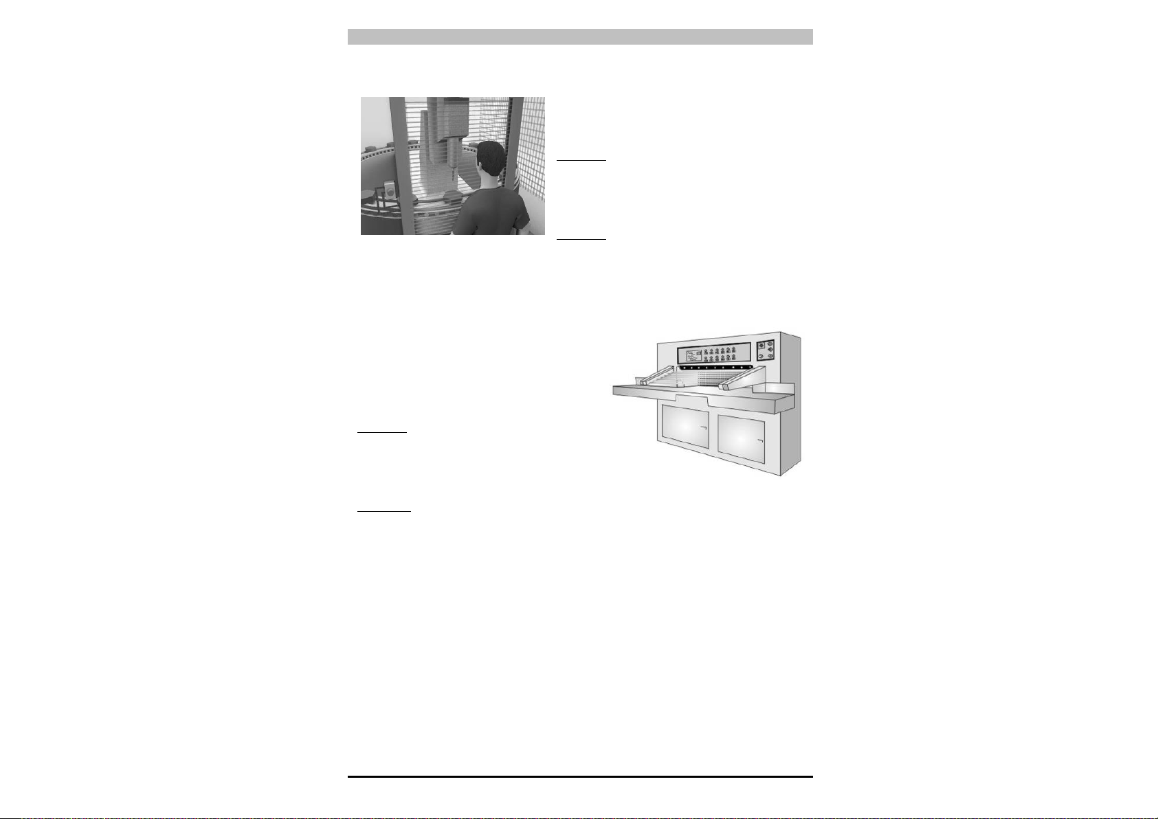
Example 1: Operating point protection on drilling machines
The operator positions the part and takes
it back after machining.
The operator must be protected against
possible abrasions while working.
Solution: PSEN op4F/H-s 14 mm safety
light curtain is especially suitable for this
kind of application, which requires the
installation of the device directly on the
machine.
Benefits: The extremely reduced profile
guarantees installation flexibility adapting itself to the machine
dimensions.
The rotating fixing brackets, supplied as accessories, speed up and
facilitate mounting.
Example 2 : Paper cutting machines
These machines typically cut paper to
a specific size for newspapers or
special applications. The operator must
be protected against abrasion or cuts
by cutter blades.
Solution: PSEN op4F/H-s 30 mm
safety light curtain is especially
suitable for this kind of application,
which require the installation of the
device directly on the machine.
Benefits: Highly reduced profile and the two side slots ensure installation
flexibility for machine dimensions.
Advantages: The extremely reduced profile guarantees installation
flexibility adapting itself to the machine dimensions.
The rotating fixing brackets, supplied as accessories, speed up and
facilitate mounting.
PSEN op4F/H-s Series Instruction Manual
10
Example 3 : Milling machines
A milling machine is a machine tool used for the shaping of metals and
other solid materials. Operator hands and body must be protected from
being dragged, entangled or cut by the tool / spindle.
Solution:
PSEN op4F/H-s 30 mm series safety light curtain is the best
solution considering the required safety levels and application type. When
even just one of the light curtain beams is interrupted, the machine is
immediately stopped.
Benefits: The extremely reduced profile guarantees installation flexibility
adapting itself to the machine dimensions.
The rotating fixing brackets, supplied as accessories, speed up and
facilitate mounting.

Instruction Manual PSEN op4F/H-s Series
11
1.5. Safety information
For a correct and safe use of the safety light curtains of the
PSEN op4F/H-s series, the following points must be observed:
• The stopping system of the machine must be electrically controlled.
• This control system must be able to stop the dangerous movement
of the machine within the total machine stopping time T as per
paragraph 1.3.3, and during all working cycle phases.
• Mounting and connection of the safety light curtain must be carried
out by qualified personnel only, according to the indications
included in the special sections (refer to sections 2; 3; 4; 5) and in
the applicable standards.
• The safety light curtain must be securely placed in a particular
position so that access to the dangerous zone is not possible
without the interruption of the beams (refer section 2 “Installation
mode”).
• The personnel operating in the dangerous area must be well trained
and must have adequate knowledge of all the operating procedures
of the safety light curtain.
• The TEST (optional for the safety light curtains Type 4) button must
be located outside the protected area because the operator must
check the protected area during all Test operation.
• The RESET/RESTART button must be located outside the
protected area because the operator must check the protected area
during all Reset/Restart operations.
Please carefully read the instructions for the correct functioning
before powering the light curtain.
PSEN op4F/H-s Series Instruction Manual
12
2. INSTALLATION MODE
2.1. Precautions to be observed for the choice and installation
Make sure that the protection level assured by the PSEN op4F/H-s
device (Type 4) is compatible with the real danger level of the
machine to be controlled, according to EN 954-1 and EN 13849-1.
• The outputs (OSSD) of the AOPD must be used as machine
stopping devices and not as command devices. The machine must
have its own START command.
• The dimension of the smallest object to be detected must be larger
than the resolution level of the device.
• The AOPD must be installed in a room complying with the technical
characteristics indicated in section 10 “Technical Data”.
• Do not install device near strong and/or flashing light sources or
close to similar devices.
• The presence of intense electromagnetic disturbances could
jeopardise device functioning. This condition shall be carefully
assessed by seeking the advice of Pilz Technical service.
• The operating distance of the device can be reduced in presence of
smog, fog or airborne dust.
• A sudden change in environment temperature, with very low
minimum peaks, can generate a small condensation layer on the
lenses and so jeopardise functioning.
Instruction Manual PSEN op4F/H-s Series
13
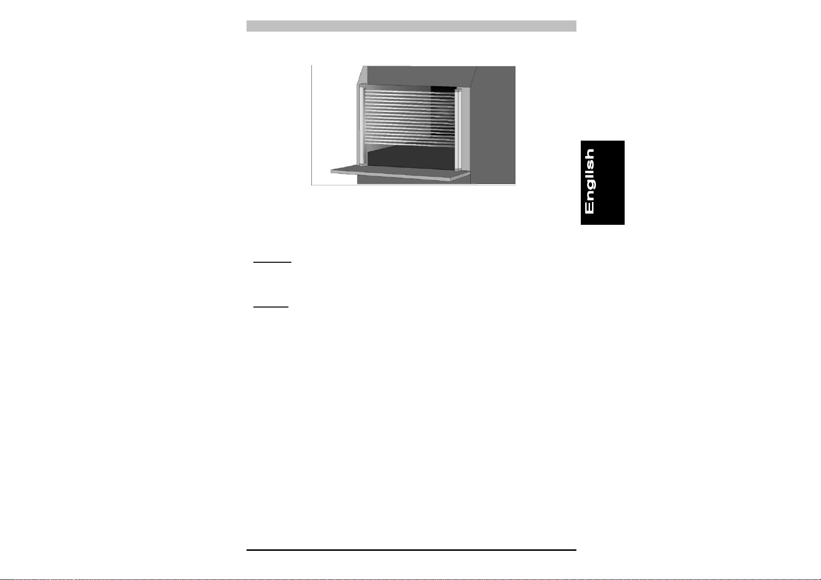
2.2. General information on device positioning
The safety light curtain should be carefully positioned, in order to
reach a very high protection standard. Access to the dangerous area
must only be possible by passing through the protecting safety light
beams.
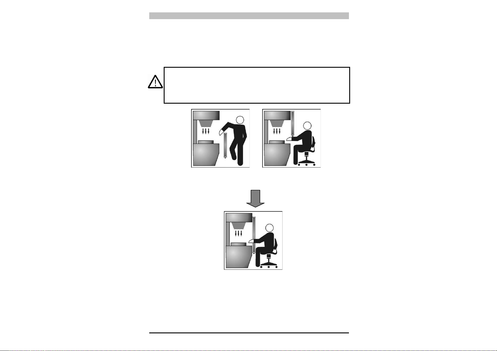
Fig.5a shows some examples of possible access to the machine
from the top and the bottom sides. These situations may be very
dangerous and so the installation of the safety light curtain at
sufficient height in order to completely cover the access to the
dangerous area (Fig.5b) becomes necessary.
Fig. 5a
Fig. 5b
Under standard operating conditions, machine starting must not be
possible while operators are inside the dangerous area.
NO
YES
PSEN op4F/H-s Series Instruction Manual
14
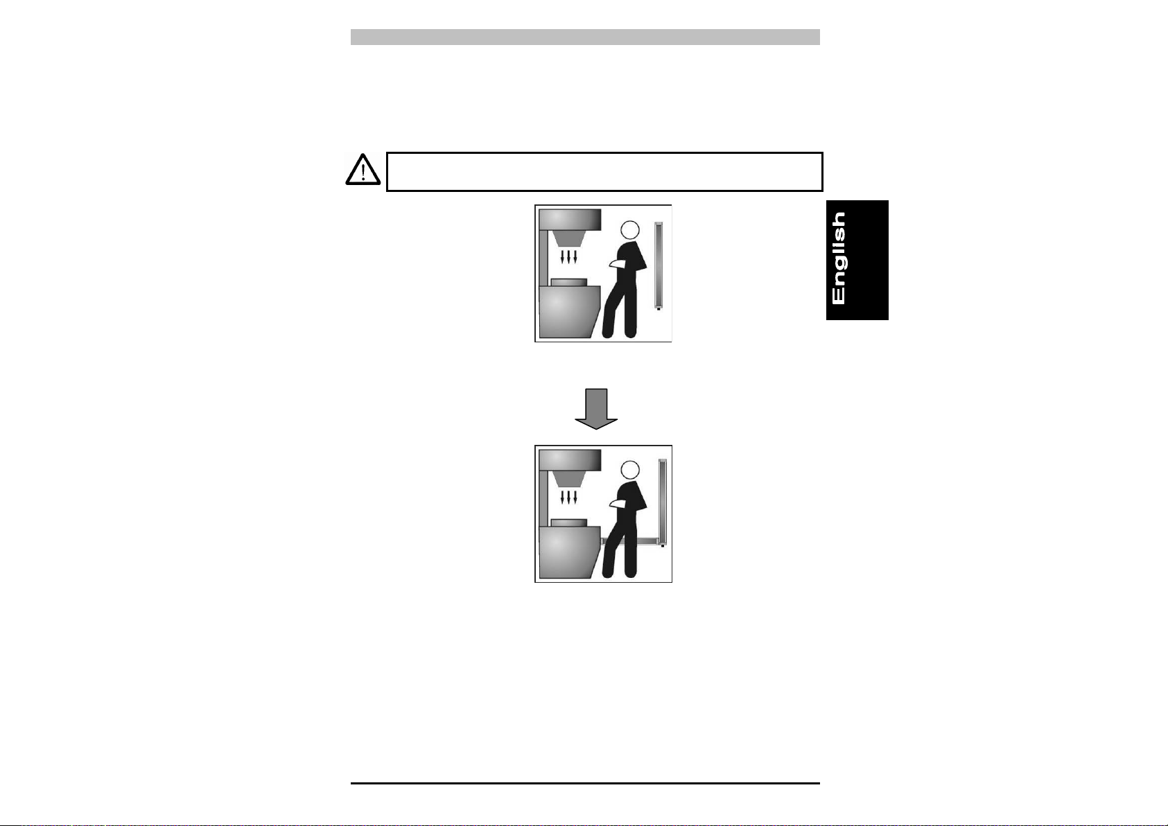
When the installation of the safety light curtain near to the dangerous
area is not possible, a second light curtain must be mounted in a
horizontal position in order to prevent any lateral access, as shown in
Fig.6b.
If the operator is able to enter the dangerous area, an additional
mechanical protection must be mounted to prevent the access.
Fig. 6a
Fig. 6b
2.2.1. Minimum installation distance
Refer to paragraph1.3.3. “Minimum installation distance”
NO
YES
Instruction Manual PSEN op4F/H-s Series
15
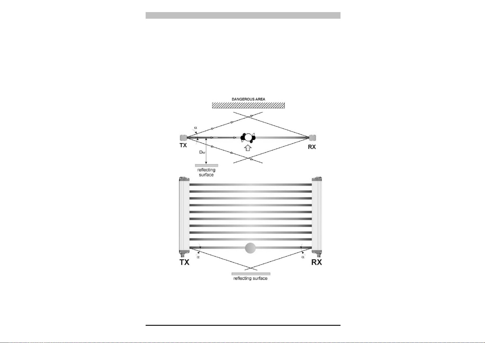
2.2.2. Minimum distance from reflecting surfaces
Reflecting surfaces placed near the light beams of the safety device
(over, under or laterally) can cause passive reflections. These
reflections can affect the recognition of an object inside the controlled
area.
However, if the RX receiver detects a secondary beam (reflected by
the side-reflecting surface) the object might not be detected, even if
the object interrupts the main beam.
Fig. 7
Loading...