


22 121-03 PSEN ma1.4a-51
4 D Betriebsanleitung
4 GB Operating instructions
4 F Manuel d'utilisation
Sicherheitsschalter PSEN ma1.4a-51 Safety switch PSEN ma1.4a-51
Der Sicherheitsschalter erfüllt Forderungen der EN 60204-1.
Der Sicherheitsschalter erfüllt EN 60947-5-3 nur zusammen mit dem Betätiger
PSEN ma1.4-03mm oder PSEN ma1.4-10mm und hierfür zugelassenen Auswertegeräten. Schließen Sie den Sicherheitsschalter nur an Auswertegeräte an, die im Abschnitt "Anschlüsse" aufgeführt sind.
The safety switch meets the requirements of EN 60204-1.
The safety switch only complies with
EN 60947-5-3 in conjunction with the actuator
PSEN ma1.4-03mm or PSEN ma1.4-10mm and its approved evaluation devices.
The safety switch should only be connected to the evaluation devices listed under "Connections".
Capteur de sécurité PSEN ma1.4a-51
Le capteur de sécurité satisfait aux exigences de l'EN 60204-1.
Le capteur de sécurité est conforme à la norme EN 60947-5-3 uniquement lorsqu'il est utilisé avec l'actionneur PSEN ma1.4-03mm ou PSEN ma1.4-10mm et les unités de contrôle spécialement homologuées.
Ne raccordez le capteur de sécurité qu'aux unités de contrôle indiquées dans le chapitre
« Raccordements ».
Zu ihrer Sicherheit
`Installieren und nehmen Sie das Gerät nur dann in Betrieb, wenn Sie diese Betriebsanleitung gelesen und verstanden haben und Sie mit den geltenden Vorschriften über Arbeitssicherheit und Unfallverhütung vertraut sind.
Beachten Sie die VDEsowie die örtlichen Vorschriften, insbesondere hinsichtlich Schutzmaßnahmen
`Durch Öffnen des Gehäuses oder eigenmächtige Umbauten erlischt jegliche Gewährleistung.
For your safety
`Only install and commission the unit if you have read and understood these operating instructions and are familiar with the applicable regulations for health and safety at work and accident prevention.
Ensure VDE and local regulations are met, especially those relating to safety.
`Any guarantee is rendered invalid if the housing is opened or unauthorised modifications are carried out.
Pour votre sécurité
`Vous n'installerez l'appareil et ne le mettrez en service qu'après avoir lu et compris le présent manuel d'utilisation et vous être familiarisé avec les prescriptions en vigueur sur la sécurité du travail et la prévention des accidents.
Respectez les normes locales ou VDE, particulièrement en ce qui concerne la sécurité.
`L'ouverture de l'appareil ou sa modification annule automatiquement la garantie.
Gerätemerkmale
`Zum Sicherheitsschalter gehört der Betätiger
PSEN ma1.4-03mm oder PSEN ma1.4-
10mm
`Sicherheitsschalter mit Kabel (5 m)
`2 Sicherheitskontakte (Schließer)
`1 Hilfskontakt (Schließer)
`Betätiger PSEN ma1.4-03mm:
–Gesicherter Schaltabstand: 3 mm
–Gesicherter Ausschaltabstand: 12 mm
`Betätiger PSEN ma1.4-10mm:
–Gesicherter Schaltabstand: 10 mm
–Gesicherter Ausschaltabstand: 22 mm
`eckige Bauform
`Wirkweise magnetisch
`Schaltspannung 24 V DC
`LED zur Anzeige des Schaltzustands
Unit features |
Caractéristiques de l'appareil |
||
` The safety switch is used with the actuator |
` L'actionneur PSEN ma1.4-03mm ou |
||
PSEN ma1.4-03mm or PSEN ma1.4-10mm |
PSEN ma1.4-10mm est associé au capteur |
||
` Safety switch with cable (5 m) |
de sécurité. |
||
` 2 safety contacts (N/O) |
` Capteur de sécurité avec câble (5 m) |
||
` 1 auxiliary contact (N/O) |
` 2 contacts de sécurité (contacts à fermeture) |
||
` Actuator PSEN ma1.4-03mm: |
` 1 contact d'information (contact à fermeture) |
||
– |
Assured operating distance: 3 mm |
` Actionneur PSEN ma1.4-03mm : |
|
– |
Assured release distance: 12 mm |
– |
Distance de commutation de sécurité : |
` Actuator PSEN ma1.4-10mm: |
|
3 mm |
|
– |
Assured operating distance: 10 mm |
– |
Distance de déclenchement de |
– |
Assured release distance: 22 mm |
|
sécurité : 12 mm |
` Square design |
` Actionneur PSEN ma1.4-10mm : |
||
` Works magnetically |
– |
Distance de commutation de sécurité : |
|
` Switching voltage 24 VDC |
|
10 mm |
|
` LED to display switch status |
– |
Distance de déclenchement de |
|
sécurité : 22 mm
` architecture rectangulaire ` actionnement magnétique ` tension commutée 24 V DC
` LED pour l'affichage de l'état de commutation
- 1 -

Schaltabstände |
Operating distances |
|
Distances de commutation |
|||
1 |
2 |
3 |
|
|
|
|
|
y |
|
|
|
|
|
|
Ein/On/Marche |
|
|
|
|
|
|
Aus/Off/Arrêt |
|
|
|
|
|
|
|
somin |
sao so |
sr |
sar |
(mm) x |
Legende |
Key |
|
Légende |
|
|
|
` c: Seitenversatz |
|
|
` c: Lateral offset |
|
` c: Décalage latéral |
|
|||||
` d: Höhenversatz |
|
|
` d: Vertical offset |
|
` d: Décalage en hauteur |
|
|||||
` e: Schaltzustände (y-Achse) in Abhängigkeit |
` e: Switch statuses (y-axis) dependent on the |
` e: Etats de commutation (axe y) en fonction |
|||||||||
des Schaltabstands (x-Achse) |
|
operating distance (x-axis) |
|
de la distance de commutation (axe x) |
|||||||
` BetätigerPSEN ma1.4-03mm |
|
` ActuatorPSEN ma1.4-03mm |
|
` Actionneur PSEN ma1.4-03mm |
|||||||
– |
Somin: Minimaler Schaltabstand: 0,0 mm |
– |
Somin: Minimum operating distance: |
– |
Somin : Distance de commutation |
||||||
– |
Sao: Gesicherter Schaltabstand: 3 mm |
|
0,0 mm |
|
|
minimale : 0,0 mm |
|
||||
– |
So: Typischer Schaltabstand: 3,5 mm |
– |
Sao: Assured operating distance: 3 mm |
– |
sao : Distance de commutation de |
||||||
– |
Sr: Typischer Ausschaltabstand: 6 mm |
– |
So: Typical operating distance: 3,5 mm |
|
sécurité : 3 mm |
|
|||||
– |
Sar: Gesicherter Ausschaltabstand: |
|
– |
Sr: Typical release distance: 6 mm |
– |
So : Distance de commutation approxima- |
|||||
|
12 mm |
|
|
– |
Sar: Assured release distance: 12 mm |
|
tive : 3,5 mm |
|
|||
` Betätiger PSEN ma1.4-10mm |
|
` Actuator PSEN ma1.4-10mm |
|
– Sr : Distance approximative de déclenche- |
|||||||
– |
Somin: Minimaler Schaltabstand: 0,0 mm |
– |
Somin: Minimum operating distance: |
|
ment : 6 mm |
|
|||||
– |
Sao: Gesicherter Schaltabstand: 10 mm |
|
0,0 mm |
|
– |
Sar : Distance de déclenchement de sécu- |
|||||
– |
So: Typischer Schaltabstand: 12,5 mm |
– |
Sao: Assured operating distance: 10 mm |
|
rité : 12 mm |
|
|||||
– |
Sr: Typischer Ausschaltabstand: 16 mm |
– |
So: Typical operating distance: 12,5 mm |
` Actionneur PSEN ma1.4-10mm |
|||||||
– |
Sar: Gesicherter Ausschaltabstand: |
|
– |
Sr: Typical release distance: 16 mm |
– |
Somin : Distance de commutation |
|||||
|
22 mm |
|
|
– |
Sar: Assured release distance: 22 mm |
|
minimale : 0,0 mm |
|
|||
|
|
|
|
|
|
|
|
– sao : Distance de commutation de |
|||
|
|
|
|
|
|
|
|
|
sécurité : 10 mm |
|
|
|
|
|
|
|
|
|
|
– So : Distance de commutation approxima- |
|||
|
|
|
|
|
|
|
|
|
tive : 12,5 mm |
|
|
|
|
|
|
|
|
|
|
– Sr : Distance approximative de déclenche- |
|||
|
|
|
|
|
|
|
|
|
ment : 16 mm |
|
|
|
|
|
|
|
|
|
|
– Sar : Distance de déclenchement de sécu- |
|||
|
|
|
|
|
|
|
|
|
rité : 22 mm |
|
|
Seitenund Höhenversatz |
|
Lateral and vertical offset |
|
Décalage latéral et en hauteur |
|||||||
` Betätiger PSEN ma1.4-03mm |
|
` Actuator PSEN ma1.4-03mm |
|
` Actionneur PSEN ma1.4-03mm |
|||||||
Gesicherter Ausschaltabstand Sar: Max. 12 mm Assured release distance Sar: Max. 12 mm with |
Distance de déclenchement de sécurité Sar : |
||||||||||
bei alle Höhenund Seitenversätzen |
|
all vertical and lateral offsets |
|
12 mm max. pour tous les décalages latéraux |
|||||||
|
|
|
|
|
|
|
|
et en hauteur |
|
||
|
|
|
|
|
|
|
|||||
Gesicherter Schaltabstand Sao in mm/Assured operating distance Sao in mm/Distance de commutation de sécurité Sao en mm |
|||||||||||
|
|
Seitenversatz/Lateral offset/ Décalage latéral |
|
|
|
|
|
||||
Höhenversatz/ |
|
|
|
|
|
|
|
|
|
|
|
|
0 |
|
|
1 |
2 |
|
|
3 |
4 |
||
Height offset/ |
|
|
|
|
|
||||||
|
|
|
|
|
|
|
|
|
|
||
0 |
3,0 |
|
|
3,0 |
2,5 |
|
|
1,5 |
1,0 |
||
Décalage en |
|
|
|
|
|||||||
|
|
|
|
|
|
|
|
|
|
||
hauteur |
1 |
3,0 |
|
|
2,5 |
2,0 |
|
|
0,5 |
- |
|
|
|
|
|
|
|
|
|
|
|
|
|
|
|
2 |
2,5 |
|
|
1,5 |
1,0 |
|
|
- |
- |
|
|
|
|
|
|
|
|
|
|
|
|
|
|
3 |
1,5 |
|
|
0,5 |
- |
|
|
- |
- |
|
|
|
|
|
|
|
|
|
|
|
|
|
|
4 |
0,5 |
|
|
- |
- |
|
|
- |
- |
|
|
|
|
|
|
|
|
|
|
|
|
Die angegebenen Werte sind gültig bei einer
Temperatur von 20 °C.
` Betätiger PSEN ma1.4-10mm
Gesicherter Ausschaltabstand Sar: Max. 22 mm bei alle Höhenund Seitenversätzen
The stated values are valid at a temperature of
20 °C.
` Actuator PSEN ma1.4-10mm
Assured release distance Sar: Max. 22 mm with all vertical and lateral offsets
Les valeurs indiquées sont valables pour une
température de 20 °C.
` Actionneur PSEN ma1.4-10mm
Distance de déclenchement de sécurité Sar : 22 mm max. pour tous les décalages latéraux et en hauteur
Gesicherter Schaltabstand Sao in mm/Assured operating distance Sao in mm/Distance de commutation de sécurité Sao en mm
|
Seitenversatz/Lateral offset/ Décalage latéral |
|
|
|
|||
Höhenversatz/ |
|
|
|
|
|
|
|
|
0 |
2 |
4 |
6 |
8 |
||
Height offset/ |
|
||||||
|
|
|
|
|
|
||
0 |
10,0 |
10,0 |
9,0 |
7,0 |
5,0 |
||
Décalage en |
|||||||
|
|
|
|
|
|
||
hauteur |
2 |
10,0 |
10,0 |
8,0 |
6,0 |
3,0 |
|
|
|
|
|
|
|
|
|
|
4 |
9,0 |
8,0 |
7,0 |
5,0 |
- |
|
|
|
|
|
|
|
|
|
|
6 |
7,0 |
6,0 |
5,0 |
- |
- |
|
|
|
|
|
|
|
|
|
Die angegebenen Werte sind gültig bei einer Temperatur von 20 °C.
The stated values are valid at a temperature of 20 °C.
Les valeurs indiquées sont valables pour une température de 20 °C.
- 2 -
Verdrahtung
Beachten Sie:
`Angaben im Abschnitt „Technische Daten“ unbedingt einhalten.
`Berechnung der max. Leitungslänge Imax im Eingangskreis:
Imax = Rlmax
Rl / km
Rlmax = max. Gesamtleitungswiderstand (s. techn. Daten)
Rl / km = Leitungswiderstand/km
`Beachten Sie bei Einsatz von Auswertegeräten mit rückfallverzögerten Kontakten:
–Verzögerungszeit ≤30 s: die rückfallverzögerten Kontakte genügen den Anforderungen der Kategorie 3 gemäß EN 954-1 bzw. den Anforderungen an PDF mit Einfehlersicherheit (PDF-S).
–Verzögerungszeit ≥ 30 s: die rückfallverzögerten Kontakte genügen den Anforderungen der Kategorie 1 gemäß EN 954-1 bzw. den Anforderungen an PDF mit Zuverlässigkeit durch besonderes Design (PDF-D).
`Überprüfen Sie in folgenden Fällen von Inbetriebnahme die Funktion Querschlusserkennung:
–Bei Auswertegeräten mit Versorgungsspannung DC: Gesamtleitungswiderstand
≥15 Ohm pro Kanal
–Bei Auswertegeräten mit Versorgungsspannung AC: Gesamtleitungswiderstand
≥25 Ohm pro Kanal
–Wie Sie die Querschlussprüfung durchführen müssen, entnehmen Sie der entsprechenden Bedienungsanleitung des Auswertegeräts.
Wiring
Please note:
`Information given in the “Technical details” must be followed.
`Calculation of the max. cable runs lmax in the input circuit:
Imax = Rlmax
Rl / km
Rlmax = max. overall cable resistance (see Technical details)
Rl / km = cable resistance/km
`When using evaluation devices with delay-on de-energisation contacts, please note:
–Delay time ≤30 s: Delay-on de-energisation contacts satisfy the requirements of category 3 in accordance with EN 954-1 and the requirements of a PDF with single-fault tolerance (PDF-S).
–Delay time ≥ 30 s: Delay-on de-energisa- tion contacts satisfy the requirements of Category 1 in accordance with EN 954-1 and the requirements of a PDF with designed reliability (PDF-D).
`In the following commissioning cases, check the function that detects shorts across contacts:
–On evaluation devices with DC supply
voltage: Overall cable resistance ≥ 15 Ohms per channel
–On evaluation devices with AC supply voltage: Overall cable resistance ≥ 25 Ohms per channel
–For details of how to perform the test for shorts across the contacts, please refer to the operating manual for the relevant evaluation device.
Câblage
Important :
`Tenez compte impérativement des données indiquées au chapitre "Caractéristiques techniques".
`Calcul de la longueur de câble max. Imax sur le circuit d'entrée :
Imax = Rlmax
Rl / km
Rlmax = résistance max. de l'ensemble du câblage (voir les caractéristiques techniques)
Rl /km = résistance du câblage/km
`En cas de mise en œuvre d'appareils de contrôle avec contacts temporisés à la retombée, il faut tenir compte des indications suivantes :
–Temporisation ≤30 s : les contacts temporisés à la retombée satisfont aux prescriptions de la catégorie 3 selon l'EN 954-1, et/ ou aux prescriptions des PDF avec sécurité de défaut unique (PDF-S).
–Temporisation ≥ 30 s : les contacts temporisés à la retombée satisfont aux prescriptions de la catégorie 1 selon l'EN 954-1, et/ ou aux prescriptions des PDF avec une fiabilité obtenue grâce à un design particulier (PDF-D).
`Vérifiez dans les cas suivants de mise en service la fonction de détection des courtscircuits :
–pour les appareils de contrôle avec ali-
mentation DC : Résistance de l'ensemble du câblage ≥ 15 ohms par canal
–pour les appareils de contrôle avec ali-
mentation AC : Résistance de l'ensemble du câblage ≥ 25 ohms par canal
–vous trouverez dans la notice d'utilisation de l'appareil de contrôle comment exécuter le contrôle des courts-circuits.
Anschlüsse |
Connections |
Raccordements |
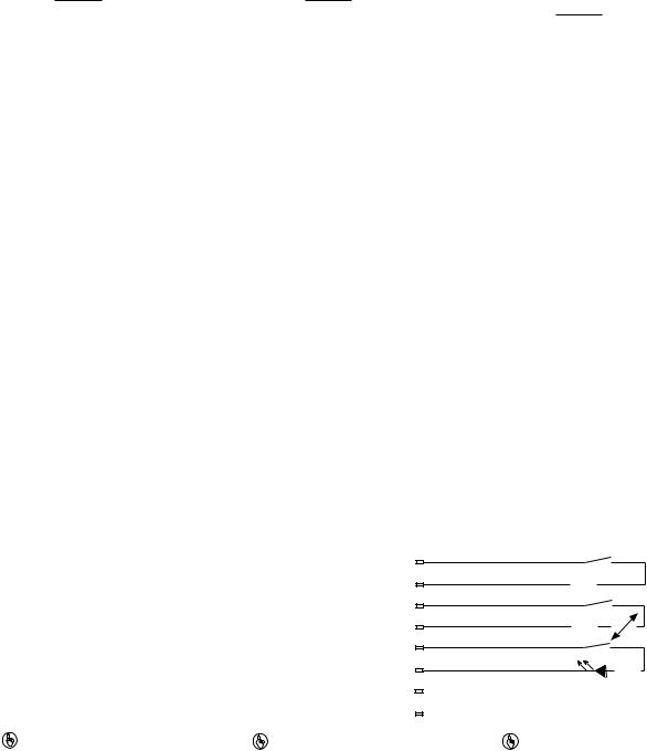
Anschlussbelegung
Der Sicherheitsschalter ist in unbetätigtem Zustand dargestellt.
Terminal assignment
The safety switch is shown in an unoperated condition.
Repérage des broches
Le capteur de sécurité est représenté en position de repos.
Belegung des 8-adrigen Kabels/Layout of the 8-core |
|
6 |
|
|
|
|
|
rosa/pink/rose |
|
|
|
|
|
|
|
|
|
|
|
|
|
|
|
||
cable/Repérage du câble à 8 conducteurs |
|
|
|
|
|
|
|
|
|
|
|
|
|
|
|
|
|
|
|
|
|
|
|||
|
|
|
|
|
|
|
grün/green/vert |
|
|
|
|
|
|
|
|
|
|
|
|
|
|
|
|||
|
|
|
3 |
|
|
|
|
|
|
|
|
|
|
|
|
|
|
|
|
|
|
|
|
||
|
|
|
1 |
|
|
|
|
|
weiß/white/blanc |
|
|
|
|
|
|
|
|
|
|
|
|
|
|
|
|
|
|
|
|
|
|
|
|
gelb/yellow/ambre |
|
|
|
|
|
|
|
|
|
|
|
|
|
|
|
||
|
|
|
4 |
|
|
|
|
|
|
|
|
|
|
|
|
|
|
|
|
|
|
|
|
||
|
|
|
2+ |
|
|
|
|
|
braun/brown/marron |
||||||||||||||||
|
|
|
|
|
|
|
|
blau/blue/bleu |
|
|
|
|
|
|
|
|
|
|
|
|
|
|
|
||
|
|
|
7 |
|
|
|
|
|
|
|
|
|
|
|
|
|
|
|
|
|
|
|
|
||
|
|
|
5 |
|
|
|
|
|
grau/grey/gris |
|
NC |
||||||||||||||
|
|
|
|
|
|
|
|
rot/red/rouge |
|||||||||||||||||
|
|
|
8 |
|
|
|
|
|
NC |
||||||||||||||||
|
|
|
|
|
|
|
|
|
|
||||||||||||||||
|
|
|
|
|
|
|
|
|
|
|
|
|
|
|
|
|
|
|
|
|
|
|
|
|
|
WICHTIG |
NOTICE |
|
|
|
IMPORTANT |
||||||||||||||||||||
Der Hilfskontakt mit LED |
The auxiliary contact with LED |
Le contact d'information avec LED |
|||||||||||||||||||||||
` darf mit PNOZ X-Geräten nur mit Versor- |
` May only be operated with a supply volt- |
` ne doit être utilisé, pour les appareils |
|||||||||||||||||||||||
gungsspannung bis 24 V DC betrieben |
|
age up to 24 VDC on PNOZ X units |
PNOZ X, qu'avec une alimentation jus- |
||||||||||||||||||||||
werden |
` May not be connected in series with |
qu'à 24 V DC |
|||||||||||||||||||||||
` ist mit PNOZ X-, PNOZelogund |
|
PNOZ X, PNOZelog and PNOZmulti |
` ne peut pas être monté en série avec les |
||||||||||||||||||||||
PNOZmulti-Geräten nicht in Reihe |
|
units |
|
|
|
appareils PNOZ X, PNOZelog et |
|||||||||||||||||||
schaltbar |
|
|
|
|
|
|
|
|
|
|
PNOZmulti |
||||||||||||||
- 3 -
 Loading...