

20879-6NL-06
PNOZ mc1p, PNOZ mc1p coated version
4
D Betriebsanleitung
4
GB Operating instructions
4
F Manuel d'utilisation
4 E Instrucciones de uso
4 I Istruzioni per l`uso
4 NL Gebruiksaanwijzing
Erweiterungsmodul PNOZ mc1p
(coated version)
Das Erweiterungsmodul PNOZ mc1p
(coated version) darf nur an ein Basisgerät
(z. B. PNOZ m1p des modularen Sicherheitssystems PNOZmulti) angeschlossen werden.
Das modulare Sicherheitssystem PNOZmulti
dient dem sicherheitsgerichteten Unterbrechen von Sicherheitsstromkreisen und ist
bestimmt für den Einsatz in:
• NOT-AUS-Einrichtungen
• Sicherheitsstromkreisen nach VDE 0113
Teil 1, 11/98 und EN 60204-1, 12/97
(z. B. bei beweglichen Verdeckungen)
Die Hilfsausgänge dürfen nicht für
sicherheitsgerichtete Funktionen
verwendet werden.
Info: Diese Anleitung beschreibt den
Betrieb des Erweiterungsmoduls
PNOZ mc1p (coated version) in
Verbindung mit dem Basisgerät PNOZ
m1p. Alle Funktionen des Basisgeräts
finden Sie in der Betriebsanleitung
"PNOZ m0p, PNOZ m1p".
Lieferumfang:
• Erweiterungsmodul PNOZ mc1p (coated
version)
• Steckbrücke
PNOZ mc1p (coated version)
expansion module
The PNOZ mc1p (coated version)
expansion module may only be connected
to a base unit (e.g. PNOZ m1p from the
PNOZmulti modular safety system). The
PNOZmulti modular safety system is used
for the safety-related interruption of safety
circuits and is designed for use in:
• Emergency stop equipment
• Safety circuits in accordance with
VDE 0113 Part 1, 11/98 and EN 60204-1,
12/97 (e.g. on movable guards)
The auxiliary outputs may not be
used for safety-related functions.
Information: These instructions
describe the operation of the
expansion module PNOZ mc1p
(coated version) with the base module
PNOZ m1p. All functions of the base
module are described in the operating
instructions "PNOZ m0p, PNOZ m1p".
Range:
• Expansion module PNOZ mc1p (coated
version)
• Link
Module d’extension PNOZ mc1p
(coated version)
Le module d’extension PNOZ mc1p (coated
version) ne doit être raccordé qu’à un
appareil de base (par exemple PNOZ m1p du
système de sécurité modulaire PNOZmulti).
Le système de sécurité modulaire PNOZmulti
est conçu pour interrompre en toute sécurité
des circuits de sécurité. Il est conçu pour être
utilisé dans les :
• circuits d’arrêt d’urgence
• circuits de sécurité selon les normes VDE
0113-1, 11/98 et EN 60204-1, 12/97
(p. ex. pour protections mobiles)
Les sorties information ne doivent
pas être utilisées pour des fonctions
de sécurité.
Information: Ce manuel d'utilisation
explique l'utilisation du module
d'extension PNOZ mc1p (coated
version) aved le module de basse
PNOZ m1p. Vous trouvez toutes les
fonctions de l'appareil de base dans le
manuel d'utilisation "PNOZ m0p,
PNOZ m1p".
Contenu de la livraison :
• Module d'extension PNOZ mc1p (coated
version)
• Cavalier de pontage
Zu Ihrer Sicherheit
Das Erweiterungsmodul PNOZ mc1p
(coated version) erfüllt alle notwendigen
Bedingungen für einen zuverlässigen
Betrieb.
Beachten Sie jedoch nachfolgend aufgeführte Sicherheitsbestimmungen:
• Installieren und nehmen Sie das Modul nur
dann in Betrieb, wenn Sie mit dieser
Betriebsanleitung und den geltenden
Vorschriften über Arbeitssicherheit und
Unfallverhütung vertraut sind.
• Verwenden Sie das Modul nur gemäß
seiner Bestimmung. Beachten Sie dazu
auch die Werte im Abschnitt "Technische
Daten".
• Halten Sie beim Transport, bei der
Lagerung und im Betrieb die Bedingungen
nach EN 60068-2-6, 01/00 ein (siehe
"Technische Daten").
• Sorgen Sie bei allen induktiven Verbrauchern für eine ausreichende Schutzbeschaltung.
• Öffnen Sie nicht das Gehäuse und
nehmen Sie auch keine eigenmächtigen
Umbauten vor.
• Schalten Sie bei Wartungsarbeiten (z. B.
beim Austausch von Schützen) unbedingt
die Versorgungsspannung ab.
Beachten Sie unbedingt die Warnhinweise in
den anderen Abschnitten dieser Anleitung.
Diese Hinweise sind optisch durch Symbole
hervorgehoben.
For your safety
The PNOZ mc1p (coated version)
expansion module meets all the necessary
conditions for reliable operation.
However, always ensure the following safety
requirements are met:
• Only install and commission the module if
you are familiar with both these
instructions and the current regulations
for health and safety at work and accident
prevention.
• Only use the module in accordance with
its intended purpose. Please also take
note of the values in the "Technical
details" section.
• Transport, storage and operating
conditions should all conform to
EN 60068-2-6, 01/00 (see "Technical
details").
• Adequate protection must be provided for
all inductive loads.
• Do not open the housing or undertake any
unauthorised modifications.
• Please make sure you shut down the
supply voltage when performing
maintenance work (e.g. replacing
contactors).
You must take note of the warnings given in
other sections of these operating instructions.
These are highlighted visually through the
use of symbols.
Pour votre sécurité
Le module d’extension PNOZ mc1p
(coated version) satisfait à toutes les
conditions nécessaires pour un
fonctionnement sûr.
Toutefois, vous êtes tenu de respecter les
prescriptions de sécurité suivantes :
• Vous n’installerez le module et ne le
mettrez en service qu’après vous être
familiarisé avec le présent manuel
d’utilisation et les prescriptions en vigueur
sur la sécurité du travail et la prévention
des accidents.
• N’utilisez le module que conformément à
l’usage auquel il est destiné. À ce sujet,
respectez les valeurs indiquées à la
section "Caractéristiques techniques".
• Pour le transport, le stockage et
l’utilisation, respectez les exigences de la
norme EN 60068-2-6, 01/00 (voir
"Caractéristiques techniques").
• Veillez à ce que les consommateurs
inductifs aient une protection suffisante.
• N’ouvrez pas le boîtier et n’effectuez pas
de modifications non autorisées.
• En cas de travaux de maintenance (p.
ex. remplacement des contacteurs),
coupez impérativement la tension
d’alimentation.
Respectez impérativement les avertissements dans les autres paragraphes du
présent manuel d’utilisation. Ces
avertissements sont signalés par des
symboles visuels.
- 1 -
Wichtig: Beachten Sie die Sicherheitsbestimmungen, sonst erlischt
jegliche Gewährleistung.
Notice: Failure to keep to these safety
regulations will render the warranty
invalid.
Important : respectez les consignes
de sécurité sinon la garantie devient
caduque.
Modulbeschreibung
Modulmerkmale:
• 16 Hilfsausgänge in Halbleitertechnik
• konfigurierbar mit PNOZmulti
Configurator
• max. 8 Erweiterungsmodule und ein
Feldbusmodul an das Basisgerät, z. B.
PNOZ m1p anschließbar
• Statusanzeigen
Zubehör:
• steckbare Schraubklemmen oder
Käfigzugfederklemmen
Funktionsbeschreibung
Arbeitsweise
Das Erweiterungsmodul PNOZ mc1p
(coated version) dient als Meldemodul mit
nicht sicheren Ausgängen.
Die Funktionsweise der Ein- und Ausgänge
des Sicherheitssystems PNOZmulti hängt
von der mit dem PNOZmulti Configurator
erstellten Sicherheitsschaltung ab. Die
Sicherheitsschaltung wird mittels Chipkarte
in das Basisgerät PNOZ m1p übertragen.
Das Basisgerät PNOZ m1p hat 2 MicroController, die sich gegenseitig überwachen.
Sie werten die Eingangskreise des Basisgeräts und der Erweiterungsmodule aus und
schalten abhängig davon die Ausgänge des
Basisgeräts und der Erweiterungsmodule.
Module description
Module features:
• 16 auxiliary outputs use semiconductor
technology
• Can be configured using the PNOZmulti
Configurator
• Max. of 8 expansion modules and one
field bus module can be connected to the
base unit, e.g.
PNOZ m1p
• Status indicators
Accessories:
• Plug-in screw terminals or cage clamp
terminals
Function description
Operation:
The expansion module PNOZ mc1p
(coated version) is used as signal module
with non-safety-related outputs.
The function of the inputs and outputs on
the PNOZmulti safety system depends on
the safety circuit created using the
PNOZmulti Configurator. A chip card is used
to download the safety circuit to the PNOZ
m1p base unit. The PNOZ m1p base unit
has 2 microcontrollers that monitor each
other. They evaluate the input circuits on the
base unit and expansion modules and
switch the outputs on the base unit and
expansion modules accordingly.
Description du module
Caractéristique du module :
• 16 sorties d’information sont sorties
statiques
• Paramétrable avec PNOZmulti
Configurator
• Possibilité de raccorder jusqu’à 8
modules d’extension et un module de bus
de terrain maximum à l’appareil de base,
p.ex. PNOZ m1p
• Affichages d’état
Accessoires :
•
Bornes débrochables à vis ou à ressort
Descriptif du fonctionnement
Fonctionnement :
Le module d'extension PNOZ mc1p (coated
version) sert de module de signification
avec des sorties non sécurisées.
Le fonctionnement des entrées et des
sorties du système de sécurité PNOZmulti
dépend du circuit de sécurité créé avec le
Configurator. Le circuit de sécurité est
transmis dans l’appareil de base PNOZ m1p
au moyen de la carte à puce. L’appareil de
base PNOZ m1p possède 2 microcontrôleurs qui se surveillent mutuellement. Ils
évaluent les circuits d’entrée de l’appareil
de base et des modules d’extension, et
activent en conséquence les sorties de
l’appareil de base et des modules
d’extension.
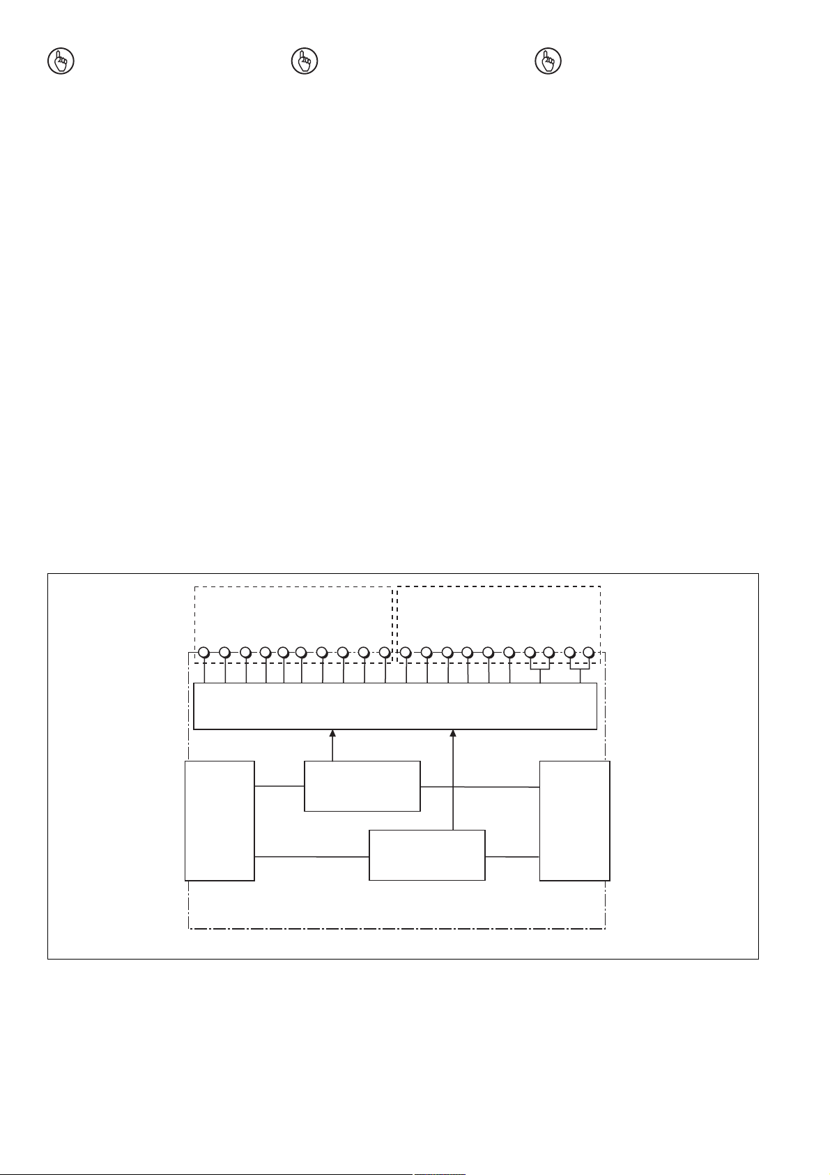
X1 X2
OA2
OA0
OA5
OA4
OA3
OA1
OA7
OA6
OA9
OA8
OA10
OA11
OA12
OA13
OA14
24 V 0 V
OA15
Hilfsausgänge, Versorgungsanschlüsse
Auxiliary outputs, supply connections
Sorties information, raccords d'alimentation
Busanschluss A
Bus connection A
Raccordement du
bus A
Busanschluss B
Bus connection B
Raccordement du
Interface
zum vorigen Modul
to previous module
avec le module
précédent
Fig. 1: Innenschaltbild Fig. 1: Internal wiring diagram Figure 1 : Schéma interne
bus B
Interface
zum nächsten Modul
to next module
avec le module
suivant
- 2 -
Funktionen
Die LEDs an Basisgerät und Erweiterungsmodulen zeigen den Status des Sicherheitssystems PNOZmulti an.
Functions:
The LEDs on the base unit and expansion
modules indicate the status of the
PNOZmulti safety system.
Fonctions :
Les LED sur l’appareil de base et les
modules d’extension indiquent l’état du
système de sécurité PNOZmulti.
Info: In der Online-Hilfe des
PNOZmulti Configurators finden Sie
Beschreibungen über die Betriebsarten und alle Funktionen des Sicherheitssystems PNOZmulti sowie
Anschlussbeispiele.
Montage
Beachten Sie bei der Montage:
Achtung! Durch elektrostatische
Entladung können Bauteile des
Sicherheitssystems beschädigt
werden. Sorgen Sie für Entladung,
bevor Sie das Sicherheitssystem
berühren, z. B. durch Berühren
einer geerdeten, leitfähigen Fläche
oder durch Tragen eines geerdeten
Armbands.
• Montieren Sie das Sicherheitssystem in
einen Schaltschrank mit einer Schutzart
von mindestens IP54.
Montieren Sie das Sicherheitssystem auf
eine waagrechte Normschiene.
Die Lüftungsschlitze müssen nach oben
und unten zeigen. Die vorgeschriebene
Einbaulage ist waagerecht (siehe
Betriebsanleitung des Basisgeräts PNOZ
m0p, PNOZ m1p). Andere Einbaulagen
können zur Zerstörung des Sicherheitssystems führen.
• Befestigen Sie das Sicherheitssystem mit
Hilfe der Rastelemente auf der Rückseite
auf der Normschiene. Führen Sie das
Sicherheitssystem gerade auf die
Normschiene, so dass die Erdungsfedern
am Sicherheitssystem auf die Normschiene gedrückt werden.
• Um die EMV-Anforderungen einzuhalten,
muss die Normschiene mit dem Schaltschrankgehäuse niederohmig verbunden
sein.
Information: The online help on the
PNOZmulti Configurator contains
descriptions of the operating modes
and all the functions of the PNOZmulti
safety system, plus connection
examples.
Installation
Please note for installation:
Caution! Electrostatic discharge
can damage components on the
safety system. Ensure against
discharge before touching the safety
system, e.g. by touching an earthed,
conductive surface or by wearing an
earthed armband.
• The safety system should be installed in a
control cabinet with a protection type of at
least IP54.
Fit the safety system to a horizontal DIN
rail. The venting slots must point up and
down. The prescribed mounting position
is horizontal (see operating instructions
of the base module PNOZ m0p, PNOZ
m1p). Other mounting positions could
damage the safety system.
• Use the notches on the back of the safety
system to attach it to a DIN rail. Connect
the safety system to the DIN rail in an
upright position so that the earthing
springs on the safety system are pressed
on to the DIN rail.
• To comply with EMC requirements, the
DIN rail must have a low-impedance
connection to the control cabinet housing.
Information : l’aide en ligne du
PNOZmulti Configurator contient la
description des modes de
fonctionnement et de toutes les
fonctions du système de sécurité
PNOZmulti ainsi que des exemples
de branchement.
Montage
Pour le montage, respectez les consignes
suivantes :
Attention ! Une décharge électrostatique peut endommager les
éléments du système de sécurité.
Veillez à vous décharger avant de
toucher le système de sécurité, par
ex. en touchant une surface
conductrice mise à la terre ou en
portant un bracelet de mise à la
terre.
• Montez le système de sécurité dans une
armoire d’indice de protection IP54 au
moins.
Montez le système de sécurité sur un rail
DIN horizontal. Les ouïes de ventilation
doivent être orientées vers le haut et vers
le bas. La position de montage horizontale est obligatoire (voir manuel d'utilisation
de l'appareil de base PNOZ m0p, PNOZ
m1p). D’autres positions de montage
pourraient provoquer une perturbation du
système de sécurité.
• Accrochez le système de sécurité sur un
rail DIN à l’aide des ergots à l’arrière de
l’appareil. Installez le système de sécurité
droit sur le rail DIN de sorte que les
ressorts de mise à la terre du système de
sécurité reposent sur le rail DIN.
• Pour respecter les exigences CEM, le rail
DIN doit être relié par une liaison à basse
impédance au corps de l’armoire.
- 3 -

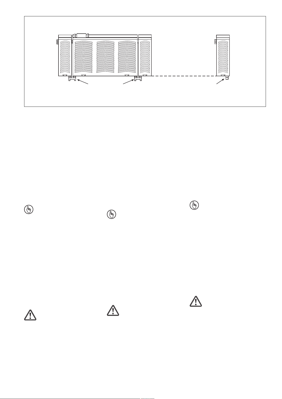
Erweiterungsmodul mit Basisgerät
verbinden
Wenn das Sicherheitssystem bereits
eingebaut ist und Sie das erste
Erweiterungsmodul anschließen, nehmen
Sie das System von der Normschiene ab.
Für die nächsten Erweiterungsmodule ist
das nciht mehr erforderlich.
Die Module werden mit Steckbrücken
verbunden. Es dürfen max. 8 Erweiterungsmodule und ein Feldbusmodul an ein
Basisgerät angeschlossen werden.
Auf der Geräterückseite des Basisgeräts
PNOZ m1p befinden sich 2 Stiftleisten. Der
seitliche Aufdruck "Termination/LInk" zeigt
die Anschlussstelle für das Erweiterungsmodul. Dort befindet sich ein Abschlussstecker.
• Entfernen Sie den Abschlussstecker.
• Verbinden Sie das Basisgerät und die
Erweiterungsmodule mit den mitgelieferten Steckbrücken (siehe Fig. 2).
• Stecken Sie den Abschlussstecker auf
das letzte Erweiterungsmodul.
• Wenn kein Feldbusmodul montiert wird,
darf auf die freie Stiftleiste am Grundgerät
kein Abschlussstecker gesteckt werden.
Connect the expansion modules and the
base module
If the safety system is installed, take it off
the rail for fitting the first expansion module.
Further expansion modules may be fitted
with the system in place.
Jumpers are used to connect the modules.
A max. of 8 expansion modules and 1 field
bus module to the base unit.
There are 2 pin connectors on the rear of
the PNOZ m1p base unit. The designation
"Termination/LInk" on the side shows where
the expansion module is to be connected.
There is a terminator.
• Remove the terminator.
• Connect the base unit and expansion
modules using the jumpers supplied (see
fig. 2).
• Fit the terminator to the last expansion
module.
• If a fieldbus module is not installed, a
terminator must not be connected to the
free pin connector on the base module.
Relier les modules d’extension et
l'appareil de base
Si le système est déjà installé, enlevez-le du
rail avant de brancher le premier module
d'extension. Ce n'est pas nécessaire pour
des modules d'extension suivants.
Les modules sont reliés par des cavaliers
de pontage. Huit modules d’extension et un
module de bus de terrain au maximum
peuvent être reliés à un appareil de base.
La face arrière de l’appareil de base
PNOZ m1p comporte 2 broches. Le point de
raccordement du module d'extension par la
côté est référé par "Termination/LInk", ou se
trouve une fiche de terminaison.
• Retirez la fiche de terminaison.
• Reliez l’appareil de base et les modules
d’extension avec les cavaliers de pontage
livrés avec les appareils (voir figure 2).
• Branchez la fiche de terminaison sur le
dernier module d’extension.
• Si aucun module bus de terrain n’est
monté, aucune fiche de terminaison ne
doit être branchée sur la broche libre de
l’appareil de base.
Feldbusmodul
Fieldbus module
Module bus de terrain
Steckbrücke
Link
Cavalier de pontage
Fig. 2: Basisgerät und Erweiterungmodule
verbinden
Inbetriebnahme
Inbetriebnahme vorbereiten:
Beachten Sie bei der Vorbereitung der
Inbetriebnahme:
• Für die Versorgungsanschlüsse 24 V und
0 V sind jeweils 2 Anschlussklemmen
vorhanden. Damit kann die Versorgungsspannung auf mehrere Anschlüsse
geschleift werden. Der Strom darf max.
3 A an jeder Klemme betragen.
• Verwenden Sie Leitungsmaterial aus
Kupferdraht mit einer Temperaturbeständigkeit von
60/75 °C.
Wichtig: Beachten Sie beim
PNOZ mc1p coated version die
eingeschränkte Gesamtleistung an
den Ausgängen bei Umgebungstemperaturen > 50 °C (siehe "Technische Daten").
Basisgerät
Base
module
Appareil de base
Erweiterungsmodul 1
Expander module 1
Module d'extension 1
Fig. 2: Connecting the base unit and
expansion modules
Commissioning
Preparing for commissioning:
Please note the following when preparing
for commissioning:
• Two connection terminals are available for
each of the supply connections 24 V and
0 V. This means that the supply voltage
can be looped through several
connections. The current at each terminal
may not exceed 3 A.
• Use copper wire that will withstand
temperatures of 60/75 °C.
Important: Note the limited overall
performance at the outputs of the
PNOZ mc1p coated version at
ambient temperatures > 50 °C
(see "Technical details").
Erweiterungsmodul 8
Expander module 8
Module d'extension 8
Abschlussstecker
Terminator
Fiche de terminaison
Figure 2 : Relier l’appareil de base et les
modules d’extension
Mise en service
Préparation de la mise en service :
Pour préparer la mise en service, respectez
les consignes suivantes :
• Les bornes d’alimentation 24 V et 0 V
(sorties statiques) ainsi que A1 et A2
(bloc d’alimentation) sont chacune
dédoublées. La tension d’alimentation
peut ainsi être dérivée sur plusieurs
autres bornes. Le courant maximal sur
chaque borne ne doit pas dépasser 3 A.
• Utilisez des fils de câblage en cuivre
supportant des températures de 60/75 °C.
Important : Pour le PNOZ mc1p
coated version, respectez la limite de
puissance totale autorisée sur les
sorties à une température d’utilisation
> 50 °C (voir "Caractéristiques
techniques").
- 4 -

Betriebsbereitschaft herstellen:
Versorgungsspannung für Ausgänge:
Legen Sie die Versorgungspannung an:
• Klemmen 24 V: + 24 V DC
• Klemmen 0 V: 0 V
Geändertes Projekt in das Sicherheitssystem PNOZmulti übertragen:
Sobald ein zusätzliches Erweiterungsmodul
mit dem System verbunden wurde, ist mit
dem PNOZmulti Configurator das Projekt zu
ändern.
Gehen Sie vor wie in der Betriebsanleitung
für das Basisgerät PNOZ m1p beschrieben.
ACHTUNG!
Nach dem Austausch der Chipkarte
prüfen, ob die Sicherheitseinrichtungen korrekt funktionieren.
Betrieb
Beim Einschalten der Versorgungsspannung übernimmt das Sicherheitssystem
PNOZmulti die Konfiguration aus der
Chipkarte. In der dafür benötigten Zeit
leuchten am Basisgerät die LEDs "POWER", "DIAG", "FAULT", "IFAULT" und
"OFAULT".
Das Sicherheitssystem PNOZmulti ist
betriebsbereit, wenn am Basisgerät die
LEDs "POWER" und "RUN" dauerhaft
leuchten.
Preparing the unit for operation:
Connect the supply voltage:
• Terminals 24 V: + 24 VDC
• Terminals 0 V: 0 V
Transfer the modified project to the
PNOZmulti safety system:
As soon as an additional expansion module
has been connected to the system, the
project must be modified using the
PNOZmulti Configurator .
Proceed as described inthe operating
instructions for the base unit PNOZ m1p.
Caution!
Check whether the safety devices
operate correctly once the chip card
has been exchanged.
Operation
When the supply voltage is switched on, the
PNOZmulti safety system copies the
configuration from the chip card. While this
is happening, the "POWER", "DIAG",
"FAULT", "IFAULT" and "OFAULT" LEDs
will light up on the base unit.
The PNOZmulti safety system is ready for
operation when the "POWER" and "RUN"
LEDs on the base unit are lit continuously.
Mise en route :
Appliquez la tension d’alimentation :
• Bornes 24 V : + 24 V CC
• Bornes 0 V : 0 V
Transférer un projet modifié dans le
système de sécurité PNOZmulti :
A la connection d'un module d'extension
additionel, il faut modifier le project à l'aide
du configurateur PNOZmulti.
Procédez comme décrit dans le manuel
d'utilisation pur l'appareil de base PNOZ
m1p.
Attention !
Une vérification des fonctions de
sécurité doit être effectuée après le
changement de la carte à puce
Exploitation
Lors de la mise sous tension, le système de
sécurité PNOZmulti charge la configuration
enregistrée sur la carte à puce. Pendant le
temps nécessaire à cette opération, les LED
suivantes sont allumées sur l’appareil de
base : "POWER", "DIAG", "FAULT",
"IFAULT" et "OFAULT".
Le système de sécurité PNOZmulti est prêt
à fonctionner lorsque les LED "POWER" et
"RUN" restent allumées.
- 5 -

Technische Daten
Technical details
Caractéristiques techniques
Elektrische Daten
Versorgungsspannung (UB)
über Basisgerät
Spannungstoleranz (UB)
Restwelligkeit (UB)
Leistungsaufnahme bei U
B
Zeiten
Einschaltverzögerung
(nach Anlegen von UB)
Überbrückung von
Spannungseinbrüchen
Hilfsausgänge
Anzahl
Spannung und Strom
PNOZ mc1p coated version
Max. Gesamtleistung bei
Umgebungstemperatur > 50 °C
Externe Spannungsversorgung (UA)
Spannungstoleranz (UA)
Galvanische Trennung
Kurzschlussschutz
Reststrom bei "0"
Signalpegel bei "1"
Statusanzeige
Umweltdaten
Luft- und Kriechstrecken
Klimabeanspruchung
PNOZ mc1p coated version
Kälte
feuchte Wärme, zyklisch
EMV
Schwingungen nach
Frequenz
Amplitude
Umgebungstemperatur
PNOZ mc1p
mit UL-Zulassung
ohne UL-Zulassung (mit Zwangs-
konvektion)
PNOZ mc1p coated version
mit UL-Zulassung
ohne UL-Zulassung
Lagertemperatur
Mechanische Daten
Schutzart
Einbauraum (z. B. Schaltschrank)
Gehäuse
Klemmenbereich
Normschiene
Hutschiene
Durchzugsbreite
Querschnitt des Außenleiters
Einzelleiter starr, mehrdrähtiger
Leiter flexibel oder mehrdrähtiger
Leiter mit Aderendhülse
Anzugsdrehmoment für
Anschlussklemmen
Gehäusematerial
Front
Gehäuse
Einbaulage
Abmessungen H x B x T
Gewicht mit Stecker
Electrical data
Supply voltage (UB)
via base unit
Voltage tolerance (UB)
Residual ripple (UB)
Power consumption at U
B
Times
Switch-on delay
(after UB is applied)
Supply interruption before
de-energisation
Auxiliary outputs
Number
Voltage and current
PNOZ mc1p coated version
Max. overall performance at an
ambient temperature > 50 °C
External supply voltage (UA)
Voltage tolerance (UA)
Galvanic isolation
Short circuit protection
Residual current at "0"
Signal level at "1"
Status display
Environmental data
Airgap creepage
Climatic suitability
PNOZ mc1p coated version
Cold
damp heat, cyclic
EMC
Vibration to
Frequency
Amplitude
Ambient temperature
PNOZ mc1p
with UL approval
without UL approval
(with forced convection)
PNOZ mc1p coated version
with UL approval
without UL approval
Storage temperature
Mechanical data
Protection type
Mounting (e.g. control cabinet)
Housing
Terminals
DIN rail
Top hat rail
Recess width
Cable cross section
Rigid single-core, flexible multi-core
or multi-core with crimp connector
Torque setting for
connection terminals
Housing material
Front panel
Housing
Fitting position
Dimensions H x W x D
Weight with connector
Données électriques
Tension d’alimentation (UB)
par l’appareil de base
Plage de la tension d'alimentation (UB)
Ondulation résiduelle (UB)
Consommation pour U
B
Temps
Temporisation d’enclenchement
(après application de UB)
Tenue aux micro-coupures
Sorties information
Nombre
Tension et courant
PNOZ mc1p coated version
Puissance totale max. à une
température d'utilisation > 50 °C
Tension d’alimentation externe (UA)
Plage de la tension d'alimentation (UA)
Séparation galvanique
Protection contr"e les courts-circuits
Courant résiduel pour signal "0"
Signal à "1"
Affichage de l'état
Environnement
Cheminement et claquage
Sollicitations climatiques
PNOZ mc1p coated version
Froid
essai cyclique de chaleur humide
CEM
Vibrations selon
Fréquence
Amplitude
Température d’utilisation
PNOZ mc1p
avec homologation UL
sans homologation UL
(avec convection forcée)
PNOZ mc1p coated version
avec homologation UL
sans homologation UL
Température de stockage
Caractéristiques mécaniques
Indice de protection
Lieu d'implantation (p. ex. armoire)
Boîtier
Bornier
Rail DIN normalisé
Support profilé
Largeur de passage
Capacité de raccordement
Conducteur monofil rigide,
conducteur multibrin flexible ou
conducteur multibrin avec embout
Couple de serrage des
bornes de raccordement
Matériau du boîtier
Face avant
Boîtier
Position de montage
Dimensions H x L x P
Poids avec connecteur
24 V DC
85...120%
+/- 5%
< 2,5 W
5 s
min. 20 ms
16
24 V DC/max. 0,5 A/
max. 12 W
144 W
24 V DC
85 ... 120 %
ja/yes/oui
ja/yes/oui
< 0,5 mA
UB - 0,5 V DC bei 0,5 A
UB -0.5 VDC at 0.5 A
UB-0,5 V DC pour 0,5 A
LED/LED/DEL
DIN VDE 0110-1, 04/97
EN 60068-2-78, 10/01
EN 60068-2-1
EN 60068-2-30
EN 60947-5-1, 11/97
EN 60068-2-6, 01/00
10 ... 55 Hz
0,35 mm
0 ... + 55 °C
0 ... + 60 °C
0 ... + 50 °C
-25 ... + 60 °C
-25 ... + 70 °C
IP54
IP20
IP20
35 x 7,5 EN 50022
27 mm
0,5 ... 1,5 mm2,
AWG 20 ... 16
0,2 ... 0,25 Nm
ABS UL 94 V0
PPO UL 94 V0
waagerecht/horozontal/
horizontale
94 x 45 x 121 mm
185 g
- 6 -

Ersatzteile Spare parts Pièces de rechange
Bezeichnung/Description/Désignation
Steckbrücke/Link/Cavalier de pontage
Steckbrücke/Link/Cavalier de pontage
Abschlussstecker/Terminator/Fiche de Terminaison
Abschlussstecker/Terminator/Fiche de Terminaison
Zubehör, z. B. Klemmen, siehe
technischer Katalog.
Accessories, e.g. terminals see
technical catalogue.
Typ/Type/Type
coated version
coated version
Accessoires, par ex. borniers voir
catalogue technique.
Bestell-Nr./Order no./Références
774 639
774 640
779 110
779 112
- 7 -

20 879-6NL-06
PNOZ mc1p, PNOZ mc1p coated version
4 E Instrucciones de uso
4 I Istruzioni per l`uso
4 NL Gebruiksaanwijzing
Módulo de ampliación PNOZ mc1p
(coated version)
El módulo de ampliación PNOZ mc1p
(coated version) puede ser conectado sólo
en un dispositivo básico (p. ej, PNOZ m1p
del sistema de seguridad modular
PNOZmulti). El sistema de seguridad
modular PNOZmulti sirve para la
interrupción, orientada a la seguridad, de
circuitos eléctricos y está diseñado para su
empleo en:
• Dispositivos de PARADA DE
EMERGENCIA
• Circuitos de seguridad según VDE 0113
parte 1, 11/98 y EN 60204-1, 12/97
(p. ej. con cubiertas móviles)
Las salidas auxiliares no deben utilizarse
para funciones orientadas a la seguridad.
Información: Estas instrucciones
describen el funcionamiento del
módulo de ampliación PNOZ mc1p
(coated version) en combinación con
el dispositivo básico PNOZ m1p.
Encontrará todas las funciones de
este dispositivo básico en las
instrucciones de uso "PNOZ m0p,
PNOZ m1p".
Volumen de suministro:
• Módulo de ampliación PNOZ mc1p
(coated version)
• Puente insertable
Modulo di espansione PNOZ mc1p
(coated version)
Il modulo di espansione PNOZ mc1p
(coated version) può essere collegato
soltanto ad un dispositivo di base (ad es.
PNOZ m1p del sistema di sicurezza
modulare PNOZmulti). Il sistema di
sicurezza modulare PNOZmulti consente
l’interruzione sicura dei circuiti di sicurezza
ed è concepito per essere utilizzato in:
• Dispositivi di arresto di emergenza
• Circuiti elettrici di sicurezza a norma VDE
0113 Parte 1, 11/98 e EN 60204-1, 12/97
(p. es. in caso di coperture mobili)
Le uscite ausiliarie non possono essere
utilizzate per le funzioni di sicurezza.
Informazione: le presenti istruzioni
descrivono il funzionamento del
modulo di espansione PNOZ mc1p
(coated version) in combinazione con
il dispositivo base
PNOZ m1p. Tutte le funzioni del
dispositivo base sono reperibili nelle
istruzioni per l’uso "PNOZ m0p, PNOZ
m1p".
Materiale della fornitura:
• Modulo di espansione PNOZ mc1p
(coated version)
• Ponticello
Uitbreidingsmodule PNOZ mc1p
(coated version)
De uitbreidingsmodule PNOZ mc1p
(coated version) mag alleen op een
basismodule (b.v. PNOZ m1p) van het
modulaire veiligheidssysteem PNOZmulti
aangesloten worden. Het modulaire
veiligheidssysteem PNOZmulti dient om
veiligheidscircuits veilig te onderbreken en
is bestemd voor gebruik in:
• noodstopvoorzieningen
• veiligheidscircuits volgens VDE 0113
deel 1, 11/98 en EN 60204-1, 12/97
(b.v. bij beweegbare afschermingen)
De hulpuitgangen mogen niet voor
veiligheidsrelevante functies gebruikt
worden.
Info: Deze handleiding beschrijft de
werking van de uitbreidingsmodule
PNOZ mc1p (coated version) in
combinatie met de basismodule
PNOZ m1p. Alle functies van de
basismodule vindt u in de gebruiksaanwijzing "PNOZ m0p, PNOZ m1p".
Inbegrepen bij levering:
• Uitbreidingsmodule PNOZ mc1p (coated
version)
• Busconnector
Para su propia seguridad
El módulo de ampliación PNOZ mc1p
(coated version) cumple todas las
condiciones que se requieren para un
funcionamiento seguro.
Aún así, tenga en cuenta las siguientes
prescripciones de seguridad:
• Instale y ponga en funcionamiento el
módulo sólo si usted está familiarizado
con estas instrucciones de uso y con las
prescripciones vigentes relativas a la
seguridad en el trabajo y a la prevención
de accidentes.
• Utilice el módulo solo para la aplicación a
la que está destinado. Tenga en cuenta
los valores indicados en la sección "Datos
técnicos".
• Durante el transporte, el almacenaje y el
funcionamiento hay que atenerse a las
condiciones conforme a EN 60068-2-6,
01/00 (véase "Datos técnicos").
• Compruebe que haya un conexionado de
seguridad suficiente en todos los
consumidores con cargas capacitivas e
inductivas.
• No abra la carcasa ni lleve a cabo
remodelación alguna por cuenta propia.
• Desconecte siempre la tensión de
alimentación durante los trabajos de
mantenimiento (p. ej. al cambiar los
contactores).
Per la vostra sicurezza
Il modulo di espansione PNOZ mc1p
(coated version) risponde a tutte le
condizioni necessarie per un funzionamento
sicuro.
È tuttavia necessario osservare le seguenti
norme di sicurezza:
• Il modulo può venire installato e messo in
funzione solo se si conoscono bene le
presenti istruzioni per l'uso e le
disposizioni vigenti relative alla sicurezza
di lavoro e all'antinforunistica.
• Utilizzare il modulo solo in base alle
disposizioni ad esso riferite. Osservare
anche i valori indicati al paragrafo "Dati
tecnici".
• Durante il trasporto, l’immagazzinamento
e il funzionamento attenersi alle
condizioni prescritte dalla norma
EN 60068-2-6, 01/00 (v. Dati tecnici).
• Assicurare un'adeguata protezione per
tutti i carichi capacitivi e induttivi.
• Non aprire la custodia e non apportare
modifiche non autorizzate.
• Assicuratevi di aver interrotto la tensione
di alimentazione prima di procedere a
lavori di manutenzione (es. quando si
sostituiscono i contattori).
Voor uw veiligheid
De uitbreidingsmodule PNOZ mc1p (coated
version) voldoet aan alle noodzakelijke
voorwaarden voor een betrouwbare
werking.
Neem echter de volgende
veiligheidsvoorschriften in acht:
• Installeer en neem de module alleen in
gebruik, als u vertrouwd bent met deze
gebruiksaanwijzing en de geldende
voorschriften op het gebied van
arbeidsveiligheid en ongevallenpreventie.
• Gebruik de module alleen waarvoor hij
bestemd is. Neem daartoe ook de
waarden in de paragraaf "Technische
gegevens" in acht.
• Neem bij transport, opslag en in bedrijf de
richtlijnen volgens EN 60068-2-6, 01/00 in
acht (zie "Technische gegevens").
• Zorg bij alle capacitieve en inductieve
belastingen voor een afdoende bescherming.
• Open de behuizing niet en bouw het
apparaat ook niet eigenmachtig om.
• Schakel bij onderhoudswerkzaamheden
(b.v. bij het vervangen van
magneetschakelaars) beslist de
voedingsspanning uit.
- 8 -

Es estrictamente necesario que observe las
indicaciones de advertencia en las otras
secciones de estas instrucciones. Estas
indicaciones están resaltadas ópticamente
por medio de símbolos.
Importante: observe las prescripciones de seguridad, en caso contrario
se extingue toda garantía.
Osservare le avvertenze presenti nelle altre
sezioni delle presenti istruzioni. Queste
indicazioni sono evidenziate da appositi
simboli.
Importante: osservare le disposizioni
per la sicurezza, poiché in caso
contrario decadrà qualsiasi diritto di
garanzia.
Neem beslist de waarschuwingen in de
andere paragrafen in deze
gebruiksaanwijzing in acht. Deze
waarschuwingen zijn met symbolen
geaccentueerd.
Belangrijk: Neem de veiligheidsvoorschriften in acht, anders vervalt
elke garantie.
Descripción del módulo
Características del módulo:
• 16 salidas auxiliares en técnica de
semiconductores
• Configurable con PNOZmulti Configurator
• En el dispositivo básico PNOZ m1p
pueden conectarse como máximo 8
módulos de ampliación y un módulo de
bus de campo
• Indicaciones de estado
Accesorios:
• Bornes enchufables de tornillo o de
resorte
Descripción del funcionamiento
Modo de trabajo:
El módulo de ampliación PNOZ mc1p
(coated version) sirve como módulo de
aviso con salidas no seguras.
El modo de funcionamiento de las entradas y
salidas del sistema de seguridad PNOZmulti
depende del circuito de seguridad elaborado
mediante el PNOZmulti Configurator. El
circuito de seguridad es transferido al
dispositivo básico PNOZ m1p mediante la
tarjeta de chip. El dispositivo básico PNOZ
m1p tiene 2 microcontroladores que se
supervisan mutuamente. Los
microcontroladores evalúan los circuitos de
entrada del dispositivo básico y de los
módulos de ampliación y, dependiendo de
ello, conmutan las salidas de los mismos.
Descrizione del modulo
Caratteristiche del modulo:
• 16 uscite ausiliarie a semiconduttore
• Configurabile con il PNOZmulti
Configurator
• Max. 8 moduli di espansione e un modulo
bus di campo collegabili al dispositivo di
base PNOZ m1p
• Visualizzazioni di stato
Accessori:
• Morsetti inseribili a vite o a molla
Descrizione del funzionamento
Modalità di lavoro:
Il modulo di espansione PNOZ mc1p
(coated version) funge da modulo di
segnale con uscite non di sicurezza.
Il funzionamento degli ingressi e delle uscite
del sistema di sicurezza PNOZmulti dipende
dal circuito di sicurezza creato con il
PNOZmulti Configurator. Il circuito di
sicurezza viene trasferito nel dispositivo di
base PNOZ m1p mediante la scheda chip. Il
dispositivo di base PNOZ m1p è dotato di 2
microcontroller che si controllano
reciprocamente. Essi analizzano i circuiti di
ingresso del dispositivo base e dei moduli di
espansione, attivando di conseguenza le
uscite del dispositivo di base e dei moduli di
espansione.
Moduulbeschrijving
Moduulkenmerken:
• 16 hulpuitgangen in halfgeleidertechniek
• Configureerbaar met PNOZmulti
Configurator
• Max. 8 uitbreidingsmodulen en een
veldbusmodule kunnen op de basismodule, b.v. PNOZ m1p aangesloten
worden
• Status-LED’s
Toebehoren:
• Steekbare schroefklemmen of
veerklemmen
Functiebeschrijving
Werking:
De uitbreidingsmodule PNOZ mc1p (coated
version) dient als meldmodule met nietveilige uitgangen.
De werking van de in- en uitgangen van het
veiligheidssysteem PNOZmulti hangt af van
de veiligheidsschakeling die met de
PNOZmulti Configurator gemaakt is. De
veiligheidsschakeling wordt met een
chipkaart naar de basismodule PNOZ m1p
overgestuurd. De basismodule PNOZ m1p
heeft 2 micro-controllers die elkaar bewaken.
Ze bewaken de ingangscircuits van de
basismodule en de uitbreidingsmodulen en
schakelen afhankelijk daarvan de uitgangen
van de basismodule en de
uitbreidingsmodulen.
X1 X2
OA2
OA4
OA1
OA0
OA3
OA5
OA7
OA6
OA9
OA8
OA10
OA11
OA12
OA13
OA14
24 V 0 V
OA15
Salidas auxiliares, conexiones de alimentación
Uscite ausiliarie, collegamenti alimentazione
Hulpuitgangen, voedingsaansluitingen
Conexión bus A
Collegamento bus A
Busaansluiting A
Conexión bus B
Collegamento bus B
Interfaz con el módulo
anterior
Interfaccia al modulo
precedente
Interface naar de
vorige module
Fig. 1: Esquema interno Fig. 1: Schema connessioni Fig. 1: Intern schema
Busaansluiting B
Interfaz con el módulo
siguiente
Interfaccia al modulo
successivo
Interface naar de
volgende module
- 9 -

Funciones:
Los LEDs en el dispositivo básico y en los
modulos de ampliación indican el estado del
sistema de seguridad PNOZmulti.
Funzioni:
I LED sul dispositivo di base e sui moduli di
espansione visualizzano lo stato del sistema
di sicurezza PNOZmulti.
Functies:
De LED’s op de basismodule en
uitbreidingsmodulen geven de status van het
veiligheidssysteem PNOZmulti weer.
Información: en la ayuda online del
PNOZmulti Configurator encontrará
descripciones sobre los modos de
funcionamiento y todas las funciones
del sistema de seguridad PNOZmulti,
así como ejemplos de conexión.
Montaje
Durante el montaje, tenga en cuenta lo
siguiente:
¡Atención!
Los componentes del sistema de
seguridad pueden resultar dañados
debido a una descarga
electrostática. Procure una descarga
de la electricidad estática del propio
cuerpo, antes de tocar el sistema,
por ejemplo tocando una superficie
conductora con descarga a tierra o
llevando puesta una muñequera con
descarga a tierra.
• El sistema de seguridad tiene que ser
montado dentro de un armario de
distribución con un grado de protección
de IP54 como mínimo.
Monte el sistema en una guía portadora
horizontal. Las rejillas de ventilación
deben señalar hacia arriba y hacia abajo.
La posición de montaje debe ser horizon-
tal (véanse las instrucciones de uso del
dispositivo básico PNOZ m0p, PNOZ
m1p). Otras posiciones de montaje
pueden tener como consecuencia la
destrucción del dispositivo.
• Fije el sistema de seguridad a una guía
normalizada con ayuda del elemento de
encaje de la parte trasera. Coloque el
sistema de seguridad, derecho, en la guía
normalizada, de tal manera que los
resortes de puesta a tierra en el sistema
hagan presión sobre la guía.
• Para cumplir con los requerimientos CEM,
la guía debe estar unida, con baja
impedancia, con la carcasa del armario de
distribución.
Conectar el dispositivo básico con los
módulos de ampliación
Si el sistema de seguridad ya está montado
y desea conectar el primer módulo de
ampliación, retire el sistema de la guía
normalizada. Para conectar los siguientes
módulos de ampliación ya no será necesario realizar esta operación.
Los módulos se conectan con puentes
insertables. Pueden conectarse como
máximo 8 módulos de ampliación y un
módulo de bus de campo en un dispositivo
básico.
En la parte posterior del dispositivo básico
PNOZ m1p hay dos clavijeros. La marca
lateral "Termination/LInk" muestra el punto
de conexión del módulo de ampliación. En
este punto hay un terminador.
• Retire el terminador.
• Conecte el dispositivo básico y los
módulos de ampliación con los puentes
insertables suministrados (véase la
figura 2)
• Conecte el terminador en el último
módulo de ampliación.
Informazione: Nella Guida Online del
PNOZmulti Configurator si possono
trovare le descrizioni relative alle
modalità di funzionamento e tutte le
funzioni del sistema di sicurezza
PNOZmulti, oltre ad alcuni esempi di
connessione.
Montaggio
In fase di montaggio osservare che:
Attenzione! Le scariche
elettrostatiche possono danneggiare i componenti del comando di
sicurezza. Scaricare l'energia
elettrostatica dal proprio prima di
toccare il comando di sicurezza, per
es. toccando una superficie
conducibile con messa a terra,
oppure indossando un bracciale con
messa a terra.
• Il sistema di sicurezza deve essere
montato in un armadio elettrico con un
tipo di protezione corrispondente almeno
al grado IP54.
Montare il sistema di sicurezza su una
guida orizzontale. le feritoie di ventilazione
devono essere rivolte verso l’alto e verso
il basso. La posizione di montaggio
prescritta è in senso orizzontale (vedi
istruzioni per l’uso del dispositivo base
PNOZ m0p, PNOZ m1p). Posizioni di
montaggio differenti possono provocare
danni irreparabili al sistema di sicurezza.
• Fissare il sistema di sicurezza su una
guida con l’aiuto dei dispositivi a scatto
situati sul retro. Applicare il sistema di
sicurezza diritto sulla guida, in modo che
le molle di messa a terra previste sul
sistema di sicurezza facciano presa sulla
guida.
• Per rispettare i requisiti di compatibilità
elettromagnetica, la guida deve essere
collegata alla custodia dell’armadio
elettrico con bassa resistenza ohmica.
Collegamento del modulo di espansione
con il dispositivo base
Se il sistema di sicurezza è già montato e si
collega il primo modulo di espansione, è
necessario prelevare il sistema dalla guida
DIN. Per i moduli di espansione successivi,
quest’operazione non è più necessaria.
I moduli vengono collegati con l’ausilio di
ponticelli. Ad ogni dispositivo di base è
consentito collegare max. 8 moduli di
espansione e un modulo bus di campo.
Sul retro del dispositivo di base PNOZm1p
sono previste 2 spine. La stampigliatura
laterale "Termination/Link" indica il punto di
collegamento per il modulo di espansione.
In tale punto è presente un connettore
terminale.
• Rimuovere il connettore terminale.
• Collegare il dispositivo base ed i moduli
di espansione mediante i ponticelli forniti
(v. fig. 2).
• Collegare il connettore terminale all’ultimo
modulo di espansione.
Info: In de on line help van de
PNOZmulti Configurator vindt u
beschrijvingen van de bedrijfsmodi,
alle functies van het veiligheidssysteem PNOZmulti en
aansluitvoorbeelden.
Montage
Neem bij montage het volgende in acht:
Let op! Door elektrostatische
ontlading kunnen componenten van
de veiligheidsschakeling beschadigd
worden. Zorg voor ontlading voordat
u de veiligheidsschakeling aanraakt,
b.v. door het aanraken van een
geaard, geleidend vlak of door het
dragen van een geaarde armband.
• Monteer het veiligheidssysteem in een
schakelkast met een beschermingsgraad
van minimaal IP54.
• Monteer het veiligheidssysteem op een
horizontale draagrail. De ventilatiegleuven
moeten omhoog en omlaag wijzen. De
voorgeschreven inbouwpositie is
horizontaal (zie de gebruiksaanwijzing
van de basismodule PNOZ m0p, PNOZ
m1p). Andere inbouwposities kunnen
ertoe leiden dat het veiligheidssysteem
defect raakt.
• Bevestig het veiligheidssysteem op een
DIN-rail met behulp van de relaisvoet op
de achterzijde. Plaats het veiligheidssysteem recht op de DIN-rail, zodat de
aardingsveren van het veiligheidssysteem
op de DIN-rail gedrukt worden.
• Om te voldoen aan de EMC-eisen, moet
de DIN-rail laagohmig met de schakelkastbehuizing verbonden zijn.
Uitbreidingsmodule met basismodule
verbinden
Wanneer het veiligheidssysteem al is
ingebouwd en u de eerste uitbreidingsmodule aansluit, neem het systeem dan van
de DIN-rail af. Voor de volgende
uitbreidingsmodule is dit niet meer noodzakelijk.
De modulen worden met busconnectoren
verbonden. Er mogen max. 8 uitbreidingsmodulen en een veldbusmodule op een
basismodule aangesloten worden.
Op de achterzijde van de basismodule
PNOZ m1p bevinden er zich 2 pennenstroken. De opdruk "Termination/LInk" op de
zijkant geeft de aansluitplaats voor de
uitbreidingsmodule aan. Hier bevindt zich
een afsluitconnector.
• Verwijder de afsluitconnector.
• Verbind de basismodule en de
uitbreidingsmodulen met de meegeleverde busconnectoren (zie afb. 2).
• Plaats de afsluitconnector op de laatste
uitbreidingsmodule.
- 10 -
Módulo de bus de campo
Modulo bus di campo
Veldbusmodule
Dispositivo básico
Dispositivo base
Basismodule
Módulo de ampliación 1
Modulo di espansione 1
Uitbreidingsmodule 1
Módulo de ampliación 8
Modulo di espansione 8
Uitbreidingsmodule 8
Puente insertable
Ponticello
Busconnectoren
Fig. 2: Conectar el dispositivo básico y los
módulos de ampliación
• Si no se monta ningún módulo de bus de
campo, no se debe insertar ningún
terminador en el clavijero libre del
dispositivo básico.
Puesta en marcha
Preparación de la puesta en marcha:
Al preparar la puesta en marcha hay que
tener en cuenta:
• Para las conexiones de alimentación de
24 V y 0 V se dispone respectivamente
de dos bornes de conexión. De esta
manera, la tensión de alimentación se
puede enlazar en varias conexiones. La
corriente en cada borne debe ser de 3 A
como máx.
• Utilizar para los cables material de
alambre de cobre con una resistencia a la
temperatura de 60/75 °C.
Importante: en el caso de
PNOZ mc1p coated version, tenga en
cuenta el límite de potencia total en
las salidas a una temperatura
ambiente > 50 °C (véase "Datos
técnicos").
Preparar el dispositivo para su
funcionamiento:
Tensión de alimantación para salidas:
Conecte la tensión de alimentación:
• Bornes 24 V: + 24 V CC
• Bornes 0 V: 0 V
Transmisión del proyecto modificado al
sistema de seguridad PNOZmulti:
Cuando se conecta al sistema un módulo de
ampliación adicional es necesario modificar
el proyecto con PNOZmulti Configurator.
Proceda según se describe en las instrucciones de uso del dispositivo básico
PNOZ m1p.
¡Atención!
funcionamiento correcto de los
dispositivos de seguridad, después
de cambiar la chipcard.
Comprobar el
Fig. 2: Collegamento del dispositivo di base
e dei moduli di espansione
• Se non viene montato il modulo bus di
campo, nella presa libera sul dispositivo
base non è consentito inserire un
connettore terminale.
Messa in funzione
Preparazione della messa in funzione:
Durante la preparazione della messa in
funzione, occorre considerare quanto
segue:
• Per i collegamenti di alimentazione a 24 V
e 0 V sono previsti rispettivamente 2
morsetti di collegamento. In questo modo,
la tensione di alimentazione può venire
erogata a diversi collegamenti. La
corrente massima consentita per morsetto
è di 3 A.
• Per i cavi, utilizzare materiale in filo di
rame con una resistenza termica intorno ai
60/75 °C.
Importante: Per il PNOZ mc1p
coated version prestare attenzione
alla potenza complessiva limitata sulle
uscite a temperature ambiente
> 50 °C (vedi "Dati tecnici").
Preparazione all’uso del dispositivo:
Tensione di alimentazione per uscite:
Applicare la tensione di alimentazione:
• Morsetti 24 V: +24 V DC
• Morsetti 0 V: 0 V
Trasmissione del progetto modificato nel
sistema di sicurezza PNOZmulti:
non appena sia stato collegato un ulteriore
modulo di espansione al sistema, è
necessario modificare il progetto con
PNOZmulti Configurator.
Procedere come descritto nelle istruzioni
per l’uso per il dispositivo base PNOZ m1p.
Attenzione! Verificare che i
dispositivi di sicurezza funzionino
correttamente una volta che la chip
card è stata sostituita.
Terminador
Connettore terminale
Afsluitstekker
Fig. 2: Basismodule en uitbreidingsmodulen
verbinden
• Als er geen veldbusmodule wordt
gemonteerd, mogen op de vrije pennenstrook op het basisrelais geen
afsluitconnectoren worden geplaatst.
Ingebruikname
Ingebruikneming voorbereiden:
Neem bij de voorbereiding van de ingebruikneming de volgende zaken in acht:
• Voor de voedingsaansluitingen 24 V en
0 V zijn telkens 2 aansluitklemmen
aanwezig. Daarmee kan de voedingsspanning over meerdere aansluitingen
verdeeld worden. De stroom mag max.
3 A op elke klem bedragen.
• Gebruik kabelmateriaal van koperdraad
met een temperatuurbestendigheid van
60/75 °C.
Belangrijk: Houd u bij PNOZ mc1p
coated version aan de beperkte totale
belasting op de uitgangen bij
omgevingstemperaturen > 50 °C (zie
"Technische gegevens").
Bedrijfsklaar maken:
Voedingsspanning van de uitgangen:
Sluit de voedingsspanning aan:
• Klemmen 24 V: + 24 V DC
• Klemmen 0 V: 0 V
Gewijzigd project verzenden naar het
veiligheidssysteem PNOZmulti:
Zodra er een extra uitbreidingsmodule met
het systeem verbonden is, kan het project
worden gewijzigd met PNOZmulti
Configurator.
Ga te werk zoals beschreven in de gebruiksaanwijzing voor de basismodule PNOZ m1p.
LET OP!
Na het vervangen van de chipkaart
moet gecontroleerd worden of de
veiligheidsvoorzieningen correct
functioneren.
- 11 -

Funcionamiento
Al conectar la tensión de alimentación, el
sistema de seguridad PNOZmulti toma la
configuración de la tarjeta de chip. Durante
el tiempo requerido para ello se iluminan en
el dispositivo básico los LEDs "POWER",
"DIAG", "FAULT", "IFAULT" y "OFAULT".
El sistema de seguridad PNOZmulti se
encuentra listo para el funcionamiento
cuando en el dispositivo básico se iluminan
permanentemente los LEDs "POWER" y
"RUN".
Funzionamento
Quando la tensione di alimentazione viene
inserita, il sistema di sicurezza PNOZmulti
rileva la configurazione dalla scheda chip.
Nell’arco di tempo necessario a questa
operazione, sul dispositivo di base si
accendono i LED "POWER", "DIAG",
"FAULT", "IFAULT" e "OFAULT".
Quando i LED "POWER" e "RUN" del
dispositivo di base rimangono
costantemente accesi, il sistema di
sicurezza PNOZmulti è pronto al
funzionamento.
Bedrijf
Bij het inschakelen van de
voedingsspanning neemt het
veiligheidssysteem PNOZmulti de
configuratie uit de chipkaart over. In de
daarvoor benodigde tijd lichten op de
basismodule de LED’s "POWER", "DIAG",
"FAULT", "IFAULT" en "OFAULT" op.
Het veiligheidssysteem PNOZmulti is
bedrijfsklaar, als op de basismodule de
LED’s "POWER" en "RUN" continu
oplichten.
- 12 -

Datos técnicos
Dati tecnici
Technische gegevens
Características eléctricas
Tensión de alimentación (UB)
a través del dispositivo básico
Tolerancia de tensión (UB)
Ondulación residual (UB)
Consumo de energía con U
B
Tiempos
Retardo a la conexión
(después de aplicar UB)
Inmunidad a cortes de tensión
Salidas auxiliares
Cantidad
Tensión y corriente
PNOZ mc1p coated version
Potencia máxima total a una
temperatura ambiente > 50 °C
Alimentación de tensión externa (UA)
Tolerancia de tensión (UA)
Separación galvánica
Protección contra cortocircuitos
Corriente residual con "0"
Nivel de señal con "1"
Indicación de estado
Datos ambientales
Distancias de fuga por aire y
superficial
Condiciones climáticas
PNOZ mc1p coated version
Frío
calor húmedo, cíclico
CEM
Oscilaciones según
Frecuencia
Amplitud
Temperatura ambiente
PNOZ mc1p
con homologación UL
sin homologación UL (con
convección forzada)
PNOZ mc1p coated version
con homologación UL
sin homologación UL
Temperatura de almacenaje
Datos mecánicos
Grado de protección
Lugar de montaje (p.ej. armario de
distribución)
Carcasa
Zona de bornes
Guía normalizada
Guía normalizada
Ancho de fijación
Sección del cable exterior
Conductor monofilar rígido,
conductor multifilar flexible o
conductor multifilar con terminal
Par de apriete para bornes de
conexión
Material de la carcasa
Frontal
Carcasa
Posición de montaje
Dimensiones Al x An x P
Peso con conector
Dati elettrici
Tensione di alimentazione (UB)
mediante dispositivo di base
Tolleranza di tensione (UB)
Ondulazione residua (UB )
Potenza assorbita a U
B
Periodi
Ritardo all'eccitazione
(dopo l’applicazione di UB)
Ininfluenza mancanza tensione
Uscite ausiliarie
Numero
Tensione e corrente
PNOZ mc1p coated version
Portata totale max. a temperatura
ambiente > 50 °C
Tensione di alimentazione esterna (UA)
Tolleranza di tensione (UA)
Separazione galvanica
Protezione contro i cortocircuiti
Corrente residua a "0"
Livello con segnale "1"
Indicatore di stato
Dati ambientali
Caratteristiche dielettriche
Sollecitazione climatica
PNOZ mc1p coated version
Freddo
caldo umido, ciclico
CEM
Vibrazioni secondo norma
Frequenza
Ampiezza
Temperatura ambiente
PNOZ mc1p
con omologazione UL
senza omologazione UL (con
convenzione forzata)
PNOZ mc1p coated version
con omologazione UL
senza omologazione UL
Temperatura di immagazzinamento
Dati meccanici
Tipo di protezione
Spazio di montaggio (p.es. quadro
elettrico ad armadio)
Custodia
Terminali
Guida Din
Guiad normalizzata
Larghezza guida
Sezione trasversale del conduttore esterno
Conduttore singolo rigido,
conduttore a più fili flessibile o
conduttore a più fili con capocorda
Coppia per
morsetti di collegamento
Materiale delle custodia
Fronte
Custodia
Posizione di montaggio
Dimensioni: altezza x larghezza x
profondità
Peso con connettore
Elektrische gegevens
Voedingsspanning (UB)
via basismodule
Spanningstolerantie (UB)
Rimpelspanning (UB)
Opgenomen vermogen bij U
B
Tijden
Inschakelvertraging
(na inschakelen van UB)
Maximale spanningsonderbreking
Hulpuitgangen
Aantal
Spanning en stroom
PNOZ mc1p coated version
Max. totale belasting bij een
omgevingstemperatuur > 50 °C
Externe voedingsspanning (UA)
Spanningstolerantie (UA)
Galvanische scheiding
Kortsluitbeveiliging
Reststroom bij "0"
Signaalniveau bij "1"
Statusweergave
Omgevingscondities
Lucht- en kruipwegen
Klimaatcondities
PNOZ mc1p coated version
Koude
vochtige warmte, cyclisch
EMC
Trillingsbestendigheid volgens
Frequentie
Amplitude
Omgevingstemperatuur
PNOZ mc1p
met UL-goedkeuring
zonder UL-goedkeuring (met
geforceerde ventilatie)
PNOZ mc1p coated version
met UL-goedkeuring
zonder UL-goedkeuring
Opslagtemperatuur
Mechanische gegevens
Beschermingsgraad
Inbouwruimte (b.v. schakelkast)
Behuizing
Aansluitklemmen
DIN-rail
Rail
Doortrekbreedte
Doorsnede van de aansluitkabels
Massieve enkele draad, meerdere
flexibele draden of meerdere draden
met adereindhuls
Aanhaalmoment voor
aansluitklemmen
Behuizingsmateriaal
Front
Behuizing
Inbouwpositie
Afmetingen h x b x d
Gewicht met connector
24 V DC
85...120%
+/- 5%
< 2,5 W
5 s
mín. 20 ms/min. 20 ms/
min. 20 ms
16
24 V DC/max. 0,5 A/max.
12 W
144 W
24 V DC
85 ... 120 %
sí/si/ja
sí/si/ja
< 0,5 mA
UB - 0,5 V CC a 0,5 A
UB - 0,5 V CC con 0,5 A
UB - 0,5 V DC bij 0,5 A
LED
DIN VDE 0110-1, 04/97
EN 60068-2-78, 10/01
EN 60068-2-1
EN 60068-2-30
EN 60947-5-1, 11/97
EN 60068-2-6, 01/00
10 ... 55 Hz
0,35 mm
0 ... + 55 °C
0 ... + 60 °C
0 ... + 50 °C
-25 ... + 60 °C
-25 ... + 70 °C
IP54
IP20
IP20
35 x 7,5 EN 50022
27 mm
0,5 ... 1,5 mm2,
AWG 20 ... 16
0,2 ... 0,25 Nm
ABS UL 94 V0
PPO UL 94 V0
horizontal/orizzontale/
horizontaal
94 x 45 x 121 mm
185 g
- 13 -

Piezas de repuesto
Ricambi Reserveonderdelen
Denominación/Denominazione/Benaming
Puente insertable/Ponticello/Busconnectoren
Puente insertable/Ponticello/Busconnectoren
Terminador/Connettore terminale/Afsluitstekker
Terminador/Connettore terminale/Afsluitstekker
Accesorios, por ejemplo bornes,
véase el catálogo técnico.
Per gli accessori, ad es. morsetti,
vedi catalogo tecnico.
Tipo/Tipo/Type
coated version
coated version
N°. de pedido/Ordine n./Bestelnr.
774 639
774 640
779 110
779 112
Zie voor toebehoren zoals klemmen
de technische catalogus.
- 14 -
DD
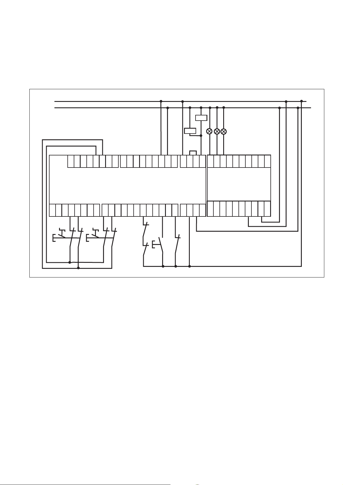
Anschlussbeispiel:
D
DD
Lampen an Hilfsausgängen
OA0 ... OA2
EE
Ejemplo de conexión:
E
EE
Lámparas en las salidas auxiliares
OA0 ... OA2
L+
L-
CI+
CI-
CO-
CO+
T0T1T2T3O0O1O2
GBGB
GB
Connection example:
GBGB
Lamps at auxiliary outputs
OA0 ... OA2
II
Esempio di collegamento:
I
II
Lampade sulle uscite ausiliarie
OA0 ... OA2
O3
OA0
24V
24V0V0V13142324
K1
K2
OA0
OA1
OA2
OA3
FF
F
Exemple de raccordement :
FF
Voyants sur les sorties d'information
OA0 ... OA2
NLNL
Aansluitvoorbeeld:
NL
NLNL
Lampen op hulpuitgangen
OA0 ... OA2
OA4
OA5
OA6
OA7
OA8
OA9
PNOZ m1p
I0I1I2I3I4I5I6I7I8I9I10
S1
S2
PNOZ mc1p
I11
I12
I13
I14
I15
I16
I17
I18
I19A1A1A2A2
OA10
OA11
OA12
OA13
OA14
OA15
24V
24V0V0V
K1
S3
S4
K2
- 15 -

4D Abmessungen in mm (")
4E
Dimensiones en mm (") 4I Dimensioni in mm (")
4GB Dimensions in mm (")
4F Dimensions en mm (")
4NL Afmetingen in mm (")
121 (4.76")
94 (3.70")
4D Anschlussbelegung
Asignación de conexiones 4I Schema delle connessioni
4E
4GB Connector pin assignment
PNPZ mc1p PNPZ mc1p coated version
773700
45
(1.77")
4F Affectation des raccords
4NL Klembezetting
Technischer Support
+49 711 3409-444 +49 711 3409-444
...
In vielen Ländern sind wir durch
unsere Tochtergesellschaften und
Handelspartner vertreten.
Nähere Informationen entnehmen
Sie bitte unserer Homepage oder
nehmen Sie Kontakt mit unserem
Stammhaus auf.
Technical support
... ...
In many countries we are
represented by our subsidiaries
and sales partners.
Please refer to our Homepage
for further details or contact our
headquarters.
Assistance technique
+49 711 3409-444
Nos filiales et partenaires
commerciaux nous représentent
dans plusieurs pays.
Pour plus de renseignements,
consultez notre site internet ou
contactez notre maison mère.
- 16 -
www
www.pilz.com
Pilz GmbH & Co. KG
Felix-Wankel-Straße 2
73760 Ostfildern, Germany
Telephone: +49 711 3409-0
Telefax: +49 711 3409-133
E-Mail: pilz.gmbh@pilz.de
Originalbetriebsanleitung/Original instructions/Notice originale/
Manual de Instrucciones original/Istruzioni originali/Originele bedrijfshandleiding
20879-6NL-06, 2010-09 Printed in Germany
 Loading...