


 Loading...
PNOZmulti communication interfaces
Configurable Control System PNOZmulti
Operating Manual-1001154-EN-13
This document is a translation of the original document.
All rights to this documentation are reserved by Pilz GmbH & Co. KG. Copies may be made for internal purposes. Suggestions and comments for improving this documentation will be gratefully received.
Pilz®, PIT®, PMI®, PNOZ®, Primo®, PSEN®, PSS®, PVIS®, SafetyBUS p®, SafetyEYE®, SafetyNET p®, the spirit of safety® are registered and protected trademarks of Pilz GmbH & Co. KG in some countries.
 SD means Secure Digital

Content
Section 1 |
Introduction |
7 |
|
|
1.1 |
Definition of symbols |
7 |
|
|
|
|
Section 2 |
Overview - Communication options |
8 |
|
|
2.1 |
Communication via the fieldbus modules |
8 |
|
2.2 |
Communication via the RS232/ETH interfaces |
9 |
|
2.3 |
Communication via Modbus/TCP |
10 |
|
|
|
|
Section 3 |
Safety |
|
11 |
|
3.1 |
Intended use |
11 |
|
3.2 |
Safety regulations |
11 |
|
3.2.1 |
Use of qualified personnel |
11 |
|
3.2.2 |
Warranty and liability |
11 |
|
3.2.3 |
Disposal |
12 |
|
|
|
|
Section 4 |
Fieldbus modules |
13 |
|
|
4.1 |
Basics |
13 |
|
4.1.1 |
Input data (to the PNOZmulti) |
13 |
|
4.1.2 |
Output data (from the PNOZmulti) |
13 |
|
4.1.3 |
Note on the PNOZ mc6p (CANopen) |
14 |
|
4.1.4 |
Assignment of Byte 0 ... Byte 3 |
16 |
|
4.1.5 |
Assignment of Byte 4 ... Byte 18 |
17 |
|
4.1.5.1 |
Example 1 |
20 |
|
4.1.5.2 |
Example 2 |
21 |
|
4.2 |
PNOZ mc2p, PNOZ mc2.1p, PNOZ mmc11p (SDO and PDO) |
21 |
|
4.2.1 |
Overview |
21 |
|
4.2.1.1 |
PNOZ mc2p |
21 |
|
4.2.1.2 |
PNOZ mc2.1p/PNOZ mmc11p |
22 |
|
4.2.2 |
Object Directory (Manufacturer Specific Profile Area) |
23 |
|
4.2.2.1 |
SDO Index 0x2000 |
23 |
|
4.2.2.2 |
SDO Index 0x2001 and Index 0x2002 |
28 |
|
4.2.2.3 |
SDO Index 0x2003 |
29 |
|
4.2.2.4 |
SDO Index 0x2100 |
34 |
|
4.2.2.5 |
SDO Index 0x2004 |
34 |
|
4.2.2.6 |
SDO Index 0x2005 |
37 |
|
4.3 |
PNOZ mc6p, PNOZ mc6.1p, PNOZ mmc6p, PNOZ mc12p (SDO) |
38 |
|
4.3.1 |
Overview |
38 |
|
4.3.2 |
System requirements |
38 |
|
4.3.3 |
Object Directory |
39 |
|
4.3.3.1 |
Index 2000 |
39 |
|
4.3.3.2 |
Index 2001 and 2002 |
42 |
|
4.3.3.3 |
Index 2003 |
44 |
|
4.3.3.4 |
Index 2004 |
48 |
|
4.3.3.5 |
Index 2005 |
51 |
|
4.3.3.6 |
Index 2100 |
51 |
|
4.4 |
PNOZ mc8p Ethernet IP / Modbus TCP |
51 |
|
4.4.1 |
Introduction |
51 |
Operating Manual PNOZmulti communication interfaces |
3 |
1001154-EN-13 |
|

Content
|
4.4.2 |
Overview |
51 |
|
4.4.3 |
Module features |
52 |
|
4.4.4 |
Assigning the IP address to your PC |
52 |
|
4.4.5 |
Setting the IP address of the expansion module |
52 |
|
4.4.6 |
Changing IP settings |
52 |
|
4.4.7 |
Data exchange |
53 |
|
4.4.7.1 |
Ethernet IP |
53 |
|
4.4.7.2 |
Modbus TCP |
53 |
|
4.4.8 |
Web interface for commissioning and testing |
54 |
|
4.4.9 |
Restricting access |
54 |
|
4.4.10 |
Input and output data |
55 |
|
4.4.10.1 |
Assigning the inputs/outputs in the PNOZmulti Configurator to the Ether- |
55 |
|
|
net IP/Modbus TCP input/output data |
|
|
4.5 |
PNOZ mc10p sercos III |
56 |
|
4.5.1 |
Overview |
56 |
|
4.5.2 |
System requirements |
56 |
|
4.5.3 |
Object buffer |
57 |
|
4.5.3.1 |
Output data |
57 |
|
4.5.3.2 |
Diagnostic word |
59 |
|
4.5.3.3 |
Status of the inputs, outputs and LEDs |
60 |
|
4.5.3.4 |
Configuration |
64 |
|
4.5.3.5 |
Element types |
67 |
|
4.5.3.6 |
Input data |
67 |
|
4.5.3.7 |
Diagnostic data |
68 |
|
4.5.4 |
Firmware/FPGA update |
69 |
|
4.5.5 |
Forcing the virtual input data |
70 |
|
4.5.6 |
Communication with the sercos III Master |
70 |
|
4.5.6.1 |
Synchronous data exchange |
70 |
|
4.5.6.2 |
Asynchronous data access |
71 |
|
4.5.7 |
Sercos Master interface |
72 |
|
4.5.7.1 |
Supported profiles |
72 |
|
4.5.7.2 |
Default settings |
73 |
|
4.5.7.3 |
Description of IDNs |
73 |
|
4.5.7.4 |
Communication channels with the PNOZmulti |
74 |
|
4.5.7.5 |
Diagnostics |
74 |
|
|
|
|
Section 5 |
RS232/Ethernet interfaces |
75 |
|
|
5.1 |
Overview |
75 |
|
5.2 |
System requirements |
75 |
|
5.3 |
Interface description |
75 |
|
5.3.1 |
Ethernet interfaces |
75 |
|
5.3.1.1 |
RJ45 interfaces ("Ethernet") |
76 |
|
5.3.1.2 |
Requirements of the connection cable and connector |
76 |
|
5.3.1.3 |
Interface configuration |
77 |
|
5.3.1.4 |
RJ45 connection cable |
77 |
|
5.3.1.5 |
Process data exchange |
77 |
|
5.3.2 |
Serial interface RS232 |
78 |
Operating Manual PNOZmulti communication interfaces |
4 |
1001154-EN-13 |
|

Content
|
5.4 |
Communication procedure |
78 |
|
5.5 |
Telegram structure |
79 |
|
5.5.1 |
Header |
80 |
|
5.5.2 |
Usable data |
80 |
|
5.5.3 |
Information data |
80 |
|
5.6 |
Usable data |
81 |
|
5.6.1 |
Virtual inputs (Input Byte 0 ... Input Byte 15) |
81 |
|
5.6.1.1 |
Mask (Mask Byte 0 ... Mask Byte 15) |
81 |
|
5.6.1.2 |
Watchdog |
81 |
|
5.6.2 |
Virtual outputs (Output Byte 0 ... Output Byte 15) |
81 |
|
5.6.3 |
LED status |
82 |
|
5.6.4 |
Tables |
82 |
|
5.7 |
Requests |
82 |
|
5.7.1 |
Send virtual inputs to the PNOZmulti |
83 |
|
5.7.2 |
Send virtual inputs to the PNOZmulti, request state of the virtual outputs |
84 |
|
|
and LED status from the PNOZmulti |
|
|
5.7.2.1 |
Control Byte (Byte 40) |
85 |
|
5.7.3 |
Request state of virtual inputs and outputs from PNOZmulti |
86 |
|
5.7.4 |
Send data from the PNOZmulti in table form |
87 |
|
5.7.5 |
Send input and output data (cf. fieldbus communication) |
88 |
|
5.7.5.1 |
Input data (to the PNOZmulti) |
88 |
|
5.7.5.2 |
Output data (from the PNOZmulti) |
89 |
|
5.7.5.3 |
Control Byte (Byte 5) |
90 |
|
5.8 |
Troubleshooting |
91 |
|
5.8.1 |
Request format does not meet specifications |
91 |
|
5.8.2 |
Error while executing a request |
91 |
|
|
|
|
Section 6 |
Modbus/TCP |
93 |
|
|
6.1 |
System requirements |
93 |
|
6.2 |
Modbus/TCP - Basics |
93 |
|
6.3 |
Modbus/TCP with PNOZmulti |
94 |
|
6.4 |
Data areas |
95 |
|
6.4.1 |
Overview |
95 |
|
6.4.2 |
Function codes |
95 |
|
6.4.3 |
Data transfer limits |
96 |
|
6.4.4 |
Assignment of data areas |
97 |
|
6.4.4.1 |
Virtual inputs |
97 |
|
6.4.4.2 |
Control Register |
98 |
|
6.4.4.3 |
Virtual outputs |
99 |
|
6.4.4.4 |
LEDs |
99 |
|
6.4.4.5 |
Configuration |
100 |
|
6.4.4.6 |
State of the inputs from the base unit and expansion modules |
102 |
|
6.4.4.7 |
State of the outputs from the base unit and expansion modules |
104 |
|
6.4.4.8 |
LED status |
105 |
|
6.4.4.9 |
Diagnostic word, element types |
108 |
|
6.4.4.10 |
Current state of the virtual inputs |
114 |
|
6.4.4.11 |
Current states of the virtual inputs for the safe Ethernet connection |
115 |
Operating Manual PNOZmulti communication interfaces |
5 |
1001154-EN-13 |
|

Content
|
6.4.4.12 |
State of process data |
115 |
|
6.4.4.13 |
Safe Ethernet connection |
116 |
|
6.4.5 |
Updating the data areas |
116 |
|
6.4.6 |
Bit addressing in a Register |
117 |
|
6.5 |
Example |
118 |
|
|
|
|
Section 7 |
Safe Ethernet connection |
119 |
|
|
7.1 |
Overview |
119 |
|
7.2 |
System requirements |
119 |
|
7.3 |
Function description |
119 |
|
7.4 |
Configuration in the PNOZmulti Configurator |
119 |
|
7.5 |
Modbus configuration |
120 |
|
7.6 |
Reaction time |
121 |
|
7.7 |
Application guidelines |
124 |
|
|
|
|
Section 8 |
Diagnostic word |
128 |
|
|
8.1 |
Introduction |
128 |
|
8.2 |
Elements with diagnostic word |
128 |
|
8.3 |
Structure of the diagnostic word |
129 |
|
8.4 |
Evaluate diagnostic word |
129 |
|
8.4.1 |
Example |
131 |
|
8.5 |
Compilation of the diagnostic words |
131 |
|
8.5.1 |
Function elements |
132 |
|
8.5.2 |
Cascading |
134 |
|
8.5.3 |
Logic elements |
134 |
|
8.5.4 |
Output elements |
141 |
|
|
|
|
Section 9 |
Appendix |
143 |
|
|
9.1 |
Table assignment |
143 |
|
9.2 |
Table 1 |
143 |
|
9.3 |
Table 3 |
149 |
|
9.4 |
Table 4 |
151 |
|
9.5 |
Table 5 |
155 |
|
9.6 |
Table 7 |
159 |
|
9.7 |
Table 8 |
166 |
|
9.8 |
Table 9 |
169 |
|
9.9 |
Table 10 |
172 |
|
9.10 |
Table 11 |
172 |
|
9.11 |
Element types |
173 |
Operating Manual PNOZmulti communication interfaces |
6 |
1001154-EN-13 |
|
Introduction
1 Introduction
1.1Definition of symbols
Information that is particularly important is identified as follows:
DANGER!
This warning must be heeded! It warns of a hazardous situation that poses an immediate threat of serious injury and death and indicates preventive measures that can be taken.
WARNING!
This warning must be heeded! It warns of a hazardous situation that could lead to serious injury and death and indicates preventive measures that can be taken.
ATTENTION!
This refers to a hazard that can lead to a less serious or minor injury plus material damage, and also provides information on preventive measures that can be taken.
CAUTION!
This describes a situation in which the product or devices could be damaged and also provides information on preventive measures that can be taken. It also highlights areas within the text that are of particular importance.
Information
This gives advice on applications and provides information on special features.
Operating Manual PNOZmulti communication interfaces |
7 |
1001154-EN-13 |
|

Overview - Communication options
2 |
Overview - Communication options |
2.1Communication via the fieldbus modules
With communication via the fieldbus modules, the data area provided by the PNOZmulti for communication is divided into subsections, which are stored in tables. Each table consists of one or more segments.
The Master (PC, PLC) can request a segment from a table. This is delivered with the next response telegram. The virtual input and output data is also transmitted in each telegram (exception: communication with CANopen).
Communication via the fieldbus modules is described in detail in the chapter entitled "Fieldbus modules".
The following device combinations are possible:
Fieldbus modules |
Base units |
|
PNOZmulti fieldbus modules |
PNOZmulti base units with inte- |
|
PNOZ mcXp |
grated RS232 interface |
|
PNOZ mXp |
||
|
PNOZmulti fieldbus modules |
PNOZmulti base units with inte- |
|
PNOZ mcXp |
grated Ethernet interface |
|
PNOZ mXp ETH |
||
|
PNOZmulti Mini fieldbus mod- |
Base units PNOZmulti Mini |
ules |
|
PNOZ mmcXp |
|
Information
If fieldbus modules are used for communication, the integrated RS232/Ethernet interface is only used to download the project during commissioning
Operating Manual PNOZmulti communication interfaces |
8 |
1001154-EN-13 |
|

Overview - Communication options
2.2Communication via the RS232/ETH interfaces
With communication via the integrated RS232 or Ethernet interface, data exchange is defined via a special protocol. This protocol is described in more detail in the chapter entitled RS232/Ethernet interfaces [ 75].
75].
The following device combinations are possible:
|
Base units PNOZmulti Mini + communication |
Base units PNOZmulti with integrated interface |
module |
Base units with inte- |
Base units PNOZmulti |
grated RS232 interface |
Mini PNOZ mmXp |
PNOZ mXp |
+ |
|
Communication mod- |
|
ule with RS232 inter- |
|
face |
|
PNOZ mmc2p |
Base units with inte- |
Base units PNOZmulti |
|
grated Ethernet inter- |
Mini PNOZ mmXp |
|
face |
+ |
|
PNOZ mXp ETH |
||
Communication mod- |
||
|
||
|
ule with Ethernet inter- |
|
|
face PNOZ mmc1p |
Information
For communication via the integrated RS232 or Ethernet interface, the interface "Inputs/outputs that are downloaded via the integrated interface" must be configured in the hardware configuration in the PNOZmulti Configurator.
Operating Manual PNOZmulti communication interfaces |
9 |
1001154-EN-13 |
|

Overview - Communication options
2.3Communication via Modbus/TCP
For data exchange with Modbus/TCP, the PNOZmulti is the connection server. All the diagnostic data is defined in one data record, to which the client has direct access.
Communication with Modbus/TCP is described in detail in the chapter entitled Modbus/ TCP [ 93].
93].
The following device combinations are possible:
|
|
Base units PNOZmulti Mini + |
|
Base units PNOZmulti with integrated interface |
Communication module |
||
PNOZmulti base units |
|
Base units PNOZmulti |
|
with Ethernet interface |
|
Mini |
|
PNOZ mXp ETH |
|
+ |
|
|
|
Communication mod- |
|
|
|
ule with Ethernet inter- |
|
|
|
face |
|
|
|
PNOZ mmc1p |
|
|
|
|
|
Information
For communication with Modbus/TCP, the interface "Inputs/outputs that are downloaded via the integrated interface" must be configured in the hardware configuration in the PNOZmulti Configurator.
Operating Manual PNOZmulti communication interfaces |
10 |
1001154-EN-13 |
|
Safety
3 Safety
3.1Intended use
The communication interface on the configurable control system PNOZmulti is used to transfer diagnostic data to an application program. The data may only be used for non-safe- ty purposes, e.g. visualisation.
CAUTION!
For details of the intended use and application of the configurable control system PNOZmulti, please refer to the operating instructions for the respective unit.
The following is deemed improper use in particular:
}Any component, technical or electrical modification to a product
}Use of a product outside the areas described in the product documentation
}Any use that is not in accordance with the documented technical details.
3.2Safety regulations
3.2.1Use of qualified personnel
The products may only be assembled, installed, programmed, commissioned, operated, maintained and decommissioned by competent persons.
A competent person is someone who, because of their training, experience and current professional activity, has the specialist knowledge required to test, assess and operate the work equipment, devices, systems, plant and machinery in accordance with the general standards and guidelines for safety technology.
It is the company’s responsibility only to employ personnel who:
}Are familiar with the basic regulations concerning health and safety / accident prevention
}Have read and understood the information provided in this description under "Safety"
}And have a good knowledge of the generic and specialist standards applicable to the specific application.
3.2.2Warranty and liability
All claims to warranty and liability will be rendered invalid if
}The product was used contrary to the purpose for which it is intended
}Damage can be attributed to not having followed the guidelines in the manual
}Operating personnel are not suitably qualified
}Any type of modification has been made (e.g. exchanging components on the PCB boards, soldering work etc.).
Operating Manual PNOZmulti communication interfaces |
11 |
1001154-EN-13 |
|

Safety
3.2.3Disposal
}In safety-related applications, please comply with the mission time tM in the safety-relat- ed characteristic data.
}When decommissioning, please comply with local regulations regarding the disposal of electronic devices (e.g. Electrical and Electronic Equipment Act).
Operating Manual PNOZmulti communication interfaces |
12 |
1001154-EN-13 |
|

Fieldbus modules
4 |
Fieldbus modules |
4.1Basics
The input and output range is each reserved an area of 20 Bytes for communication via fieldbuses; this is updated approx. every 15 ms. The Master (PC, PLC) can send 20 Bytes to the PNOZmulti and receive 20 Bytes from the PNOZmulti. The Master can process the information in bytes, words or in double words.
4.1.1Input data (to the PNOZmulti)
Double Word |
Word |
Byte |
Content |
0 |
0 |
0 |
|
|
|
|
State of virtual inputs |
|
|
1 |
|
|
|
|
|
|
|
|
|
|
1 |
2 |
|
|
|
|
|
|
|
3 |
Reserved |
|
|
|
|
1 |
2 |
4 |
Table number |
|
|
|
|
|
|
5 |
Segment number |
|
|
|
|
|
3 |
6 |
Reserved |
|
|
|
|
|
|
7 |
Reserved |
|
|
|
|
2 |
4 |
8 |
Reserved |
|
|
|
|
|
|
9 |
Reserved |
|
|
|
|
|
5 |
10 |
Reserved |
|
|
|
|
|
|
11 |
Reserved |
|
|
|
|
3 |
6 |
12 |
Reserved |
|
|
|
|
|
|
13 |
Reserved |
|
|
|
|
|
7 |
14 |
Reserved |
|
|
|
|
|
|
15 |
Reserved |
|
|
|
|
4 |
8 |
16 |
Reserved |
|
|
|
|
|
|
17 |
Reserved |
|
|
|
|
|
9 |
18 |
Reserved |
19Reserved
4.1.2Output data (from the PNOZmulti)
Double Word |
Word |
Byte |
Content |
0 |
0 |
0 |
|
|
|
|
State of virtual outputs |
|
|
1 |
|
|
|
|
|
|
|
|
|
|
1 |
2 |
|
|
|
|
|
|
|
3 |
LED status |
|
|
|
|
Operating Manual PNOZmulti communication interfaces |
13 |
1001154-EN-13 |
|

Fieldbus modules
Double Word |
Word |
Byte |
Content |
1 |
2 |
4 |
Table number |
|
|
|
|
|
|
5 |
Segment number |
|
|
|
|
|
3 |
6 |
Byte 0 of Table x, Segment y |
|
|
|
|
|
|
7 |
Byte 1 of Table x, Segment y |
|
|
|
|
2 |
4 |
8 |
. |
|
|
|
|
|
|
9 |
. |
|
|
|
|
|
5 |
10 |
. |
|
|
|
|
|
|
11 |
. |
|
|
|
|
3 |
6 |
12 |
. |
|
|
|
|
|
|
13 |
. |
|
|
|
|
|
7 |
14 |
. |
|
|
|
|
|
|
15 |
. |
|
|
|
|
4 |
8 |
16 |
. |
|
|
|
|
|
|
17 |
. |
|
|
|
|
|
9 |
18 |
Byte 12 of Table x, Segment y |
|
|
19 |
Reserved |
|
|
|
|
4.1.3Note on the PNOZ mc6p (CANopen)
The output data on the PNOZmulti is stored as follows:
|
Object Index |
Sub Index |
|
|
Byte |
(hex) |
(hex) |
PDO |
COB-ID |
0 |
2000 |
1 |
TPDO 1 |
180h |
|
|
|
|
+ node address |
1 |
2000 |
2 |
|
|
|
|
|
|
|
2 |
2000 |
3 |
|
|
|
|
|
|
|
3 |
2000 |
4 |
|
|
|
|
|
|
|
4 |
2000 |
5 |
|
|
|
|
|
|
|
5 |
2000 |
6 |
|
|
|
|
|
|
|
6 |
2000 |
7 |
|
|
7 |
2000 |
8 |
|
|
|
|
|
|
|
8 |
2000 |
9 |
TPDO 2 |
280h |
|
|
|
|
+ node address |
9 |
2000 |
A |
|
|
|
|
|
|
|
10 |
2000 |
B |
|
|
|
|
|
|
|
11 |
2000 |
C |
|
|
|
|
|
|
|
12 |
2000 |
D |
|
|
|
|
|
|
|
13 |
2000 |
E |
|
|
|
|
|
|
|
14 |
2000 |
F |
|
|
|
|
|
|
|
15 |
2000 |
10 |
|
|
|
|
|
|
|
Operating Manual PNOZmulti communication interfaces |
14 |
1001154-EN-13 |
|

Fieldbus modules
|
Object Index |
Sub Index |
|
|
Byte |
(hex) |
(hex) |
PDO |
COB-ID |
16 |
2000 |
11 |
TPDO 3 |
PNOZ mc6p: 1C0h + node |
|
|
|
|
address PNOZ mc6.1p, |
17 |
2000 |
12 |
|
|
|
PNOZ mmc6p: |
|||
|
|
|
|
|
18 |
2000 |
13 |
|
|
|
380h |
|||
|
|
|
|
|
19 |
2000 |
14 |
|
+ node address |
|
|
|
|
|
The input data on the PNOZmulti is stored as follows:
|
Object Index |
Sub Index |
|
|
Byte |
(hex) |
(hex) |
PDO |
COB-ID |
0 |
2100 |
1 |
RPDO |
200h |
|
|
|
|
+ node address |
1 |
2100 |
2 |
|
|
|
|
|
|
|
2 |
2100 |
3 |
|
|
|
|
|
|
|
3 |
2100 |
4 |
|
|
|
|
|
|
|
4 |
2100 |
5 |
|
|
|
|
|
|
|
5 |
2100 |
6 |
|
|
|
|
|
|
|
6 |
2100 |
7 |
|
|
|
|
|
|
|
7 |
2100 |
8 |
|
|
|
|
|
|
|
8 |
2100 |
9 |
RPDO 2 |
300h |
|
|
|
|
+ node address |
9 |
2100 |
A |
|
|
|
|
|
|
|
10 |
2100 |
B |
|
|
|
|
|
|
|
11 |
2100 |
C |
|
|
|
|
|
|
|
12 |
2100 |
D |
|
|
|
|
|
|
|
13 |
2100 |
E |
|
|
|
|
|
|
|
14 |
2100 |
F |
|
|
|
|
|
|
|
15 |
2100 |
10 |
|
|
|
|
|
|
|
16 |
2100 |
11 |
RPDO 3 |
PNOZ mc6p: |
|
|
|
|
240h |
17 |
2100 |
12 |
|
|
|
|
|
|
+ node address |
18 |
2100 |
13 |
|
|
|
|
|
|
PNOZ mc6.1p, PNOZ |
19 |
2100 |
14 |
|
|
|
mmc6p: |
|||
|
|
|
|
|
|
|
|
|
400h |
|
|
|
|
+ node address |
|
|
|
|
|
Key to abbreviations: |
|
|
|
|
TPDO: Transmit Process Data Object |
|
|
||
RPDO: Receive Process Data Object |
|
|
||
COB-ID: Communication Object Identifier |
|
|
||
Operating Manual PNOZmulti communication interfaces |
15 |
1001154-EN-13 |
|

Fieldbus modules
4.1.4Assignment of Byte 0 ... Byte 3
The current status of the virtual outputs configured for the fieldbus plus the current status of the LED are always stored in Byte 0 ... Byte 3. All other information is stored in various tables (see Appendix).
Input area
The virtual inputs are defined by the Master and transferred to the PNOZmulti. Each input has a number, e.g. input bit 4 of byte 1 has the number i12.
Byte |
|
|
|
|
|
|
|
|
|
|
|
|
|
|
|
|
|
0 |
i7 |
i6 |
i5 |
i4 |
i3 |
i2 |
i1 |
i0 |
|
|
|
|
|
|
|
|
|
1 |
i15 |
i14 |
i13 |
i12 |
i11 |
i10 |
i9 |
i8 |
|
|
|
|
|
|
|
|
|
2 |
i23 |
i22 |
i21 |
i20 |
i19 |
i18 |
i17 |
i16 |
|
|
|
|
|
|
|
|
|
3 |
Reserved |
|
|
|
|
|
|
|
|
|
|
|
|
|
|
|
|
Output area
The virtual outputs are defined in the PNOZmulti Configurator. Each output that is used is given a number there, e.g. o0, o5... . The status of output o0 is stored in bit 0 of byte 0; the status of output o5 is stored in bit 5 of byte 0 etc.
Byte |
|
|
|
|
|
|
|
|
|
|
|
|
|
|
|
|
|
|
|
0 |
o7 |
|
o6 |
o5 |
o4 |
o3 |
o2 |
o1 |
o0 |
|
|
|
|
|
|
|
|
|
|
1 |
o15 |
|
o14 |
o13 |
o12 |
o11 |
o10 |
o9 |
o8 |
|
|
|
|
|
|
|
|
|
|
2 |
o23 |
|
o22 |
o21 |
o20 |
o19 |
o18 |
o17 |
o16 |
|
|
|
|
|
|
|
|
|
|
The status of the LEDs is stored in Byte 3 (output area only): |
|
|
|
||||||
|
|
|
|
|
|
|
|||
Bit 0 = 1: |
|
LED OFAULT is lit or flashes |
|
|
|
|
|||
|
|
|
|
|
|
|
|||
Bit 1 = 1: |
|
LED IFAULT is lit or flashes |
|
|
|
|
|||
|
|
|
|
|
|
|
|||
Bit 2 = 1: |
|
LED FAULT is lit or flashes |
|
|
|
|
|||
|
|
|
|
|
|
|
|
||
Bit 3 = 1: |
|
LED DIAG is lit |
|
|
|
|
|
||
|
|
|
|
|
|
|
|
||
Bit 4 = 1: |
|
LED RUN is lit |
|
|
|
|
|
||
|
|
|
|||||||
Bit 5: |
|
Communication between the PNOZmulti and the fieldbus is working |
|||||||
|
|
|
|
|
|
|
|
|
|
Bit 6: |
|
Reserved |
|
|
|
|
|
|
|
|
|
|
|
|
|
|
|
|
|
Bit 7: |
|
Reserved |
|
|
|
|
|
|
|
|
|
|
|
|
|
|
|
|
|
Operating Manual PNOZmulti communication interfaces |
16 |
1001154-EN-13 |
|

Fieldbus modules
4.1.5Assignment of Byte 4 ... Byte 18
Byte |
Table |
|
|
4 |
Table number |
|
|
|
|
|
|
5 |
Segment number |
|
|
|
|
|
|
6 |
Byte 0 of Table Segment 1 |
|
|
|
|
|
|
7 |
Byte 1 of Table Segment 1 |
|
|
|
|
|
|
8 |
Byte 2 of Table Segment 1 |
|
|
|
|
|
|
9 |
Byte 3 of Table Segment 1 |
|
|
|
|
|
|
10 |
Byte 4 of Table Segment 1 |
Segment 1 |
|
|
|
||
11 |
Byte 5 of Table Segment 1 |
||
|
|||
12 |
Byte 6 of Table Segment 1 |
|
|
|
|
|
|
13 |
Byte 7 of Table Segment 1 |
|
|
|
|
|
|
14 |
Byte 8 of Table Segment 1 |
|
|
|
|
|
|
15 |
Byte 9 of Table Segment 1 |
|
|
|
|
|
|
16 |
Byte 10 of Table Segment 1 |
|
|
|
|
|
|
17 |
Byte 11 of Table Segment 1 |
|
|
|
|
|
|
18 |
Byte 12 of Table Segment 1 |
|
|
|
|
|
|
6 |
Byte 0 of Table Segment 2 |
|
|
|
|
|
|
7 |
Byte 1 of Table Segment 2 |
|
|
|
|
|
|
8 |
Byte 2 of Table Segment 2 |
|
|
|
|
|
|
9 |
Byte 3 of Table Segment 2 |
|
|
|
|
|
|
10 |
Byte 4 of Table Segment 2 |
Segment 2 |
|
|
|
||
11 |
Byte 5 of Table Segment 2 |
||
|
|||
|
|
|
|
12 |
Byte 6 of Table Segment 2 |
|
|
|
|
|
|
13 |
Byte 7 of Table Segment 2 |
|
|
|
|
|
|
14 |
Byte 8 of Table Segment 2 |
|
|
|
|
|
|
15 |
Byte 9 of Table Segment 2 |
|
|
|
|
|
|
16 |
Byte 10 of Table Segment 2 |
|
|
|
|
|
|
17 |
Byte 11 of Table Segment 2 |
|
|
|
|
|
|
18 |
Byte 12 of Table Segment 2 |
|
|
|
|
|
|
. |
. |
. |
|
. |
|
. |
|
. |
|||
. |
|
. |
|
. |
|||
|
|
|
Operating Manual PNOZmulti communication interfaces |
17 |
1001154-EN-13 |
|

Fieldbus modules
Byte |
Table |
|
|
6 |
Byte 0 of Table Segment n |
|
|
|
|
|
|
7 |
Byte 1 of Table Segment n |
|
|
|
|
|
|
8 |
Byte 2 of Table Segment n |
|
|
|
|
|
|
9 |
Byte 3 of Table Segment n |
|
|
|
|
|
|
10 |
Byte 4 of Table Segment n |
Segment n |
|
|
|
||
11 |
Byte 5 of Table Segment n |
||
|
|||
|
|
|
|
12 |
Byte 6 of Table Segment n |
|
|
|
|
|
|
13 |
Byte 7 of Table Segment n |
|
|
|
|
|
|
14 |
Byte 8 of Table Segment n |
|
|
|
|
|
|
15 |
Byte 9 of Table Segment n |
|
|
|
|
|
|
16 |
Byte 10 of Table Segment n |
|
|
|
|
|
|
17 |
Byte 11 of Table Segment n |
|
|
|
|
|
|
18 |
Byte 12 of Table Segment n |
|
|
|
|
|
Each table consists of one or more segments. Each segment is made up of 13 Bytes. The tables have a fixed assignment. The Master requests the required data using the table number and segment number. The Slave (e.g. PNOZ mc3p) repeats the two numbers and sends the requested data. If data is requested that is not available, the Slave sends the error message “FF” instead of the segment number. The segments may be requested in any sequence.
Master |
Fieldbus module |
Byte |
|
4Table No.
5Segment No.
60
..
. .
..
18 0
Byte |
|
|
4 |
|
|
Table No. |
||
5 |
Segment No. |
|
6 |
x |
|
|
. |
. |
. |
. |
|
. |
. |
|
18 |
|
|
x |
||
Operating Manual PNOZmulti communication interfaces |
18 |
1001154-EN-13 |
|
Fieldbus modules
Exception: Table 9 segment 1:
With this table you can set the expanded inputs 24 - 127 and upload the expanded outputs 24 - 127. In contrast to the other tables, in this case the Master not only requests data but also sends input data to the PNOZmulti via the fieldbus module. Each input is assigned a Bit in the segment Bytes 0 ... 12 of the input data, each output is assigned a Bit in the segment Bytes 0 ... 12 of the output data.
ATTENTION!
The expanded input Bits are only updated when table 9 segment 1 is accessed. In the event of a fieldbus error, input bits i24 ... i127 in the PNOZmulti are frozen!
Byte |
Master |
Fieldbus module |
|
|
|
4 |
|
|
Table Number 9 |
|
5Segment Number 1
6Segment Byte 0 (i24 ... i31)
..
. .
..
18 Segment Byte 12 (i120 ... i127)
Byte |
|
|
|
4 |
|
|
|
Table Number 9 |
|
||
5 |
Segment Number 1 |
|
|
6 |
Segment Byte 0 (o24 ... |
o31) |
|
|
. |
. |
|
. |
. |
|
|
. |
. |
|
|
18 Segment Byte 12 (o120 ... o127)
Operating Manual PNOZmulti communication interfaces |
19 |
1001154-EN-13 |
|

Fieldbus modules
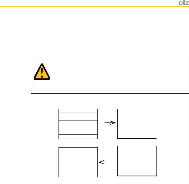
4.1.5.1Example 1
The Master requests segment 2 from table 1. The fieldbus module repeats both these details and sends segment 2. Then the data from segment 12.70 cm table 1 is transmitted.
Master |
Fieldbus module |
41
52
60
..
. .
..
18 0
4 |
1 |
5 |
2 |
6 |
x |
. |
. |
. |
. |
. |
. |
18 |
|
x |
41
55
60
..
. .
..
18 0
4 |
1 |
5 |
5 |
6 |
x |
. |
. |
. |
. |
. |
. |
18 |
|
x |
Operating Manual PNOZmulti communication interfaces |
20 |
1001154-EN-13 |
|
Fieldbus modules
4.1.5.2Example 2
The Master requests segment 1 from table 3. The fieldbus module repeats both of these details and sends segment 1. Then the Master requests segment 25 from table 5. As this table does not contain a segment 25, the Slave registers an error and sends back "FF".
Master |
Fieldbus module |
43
51
60
..
. .
..
18 0
4 |
3 |
5 |
1 |
6 |
x |
. |
. |
. |
. |
. |
. |
18 |
|
x |
45
525
60
..
. .
..
18 0
4 |
5 |
5 |
FF |
6 |
x |
. |
. |
. |
. |
. |
. |
18 |
|
x |
4.2PNOZ mc2p, PNOZ mc2.1p, PNOZ mmc11p (SDO and PDO)
4.2.1Overview
4.2.1.1PNOZ mc2p
All the objects (variables and parameters) that are relevant for these units are entered in the object directory. Service Data Objects (SDOs) are used for read and write access. The object directory is available as an EDS file (Electronic Data Sheet), enabling SDOs to be used in the PNOZ mc2p.
Operating Manual PNOZmulti communication interfaces |
21 |
1001154-EN-13 |
|

Fieldbus modules
The manufacturer-specific part of the object directory is structured as follows:
|
|
|
|
Sub-In- |
|
PDO |
Size |
Name |
Index |
dex |
Content |
0x1A00 |
128 |
TxPDO |
0x2000 |
0x01– |
Output data |
|
|
|
|
0x80 |
|
0x1A01 |
128 |
TxPDO |
0x2001 |
0x01– |
Diagnostic word (Low Byte) |
|
|
|
|
0x80 |
|
0x1A02 |
128 |
TxPDO |
0x2002 |
0x01– |
Diagnostic word (High Byte) |
|
|
|
|
0x80 |
|
0x1A03 |
128 |
TxPDO |
0x2003 |
0x01– |
Status of inputs |
|
|
|
|
0x80 |
|
|
|
|
|
Status of input LED |
|
|
|
|
|
|
|
|
|
|
|
|
|
|
|
|
|
|
State of outputs |
|
|
|
|
|
|
|
|
|
|
|
Status of LED |
|
|
|
|
|
|
0x1600 |
20 |
RxPDO |
0x2100 |
0x01– |
Input data |
|
|
|
|
0x14 |
|
Information
Data with indices 2001 to 2003 is only updated by the PNOZmulti piece by piece in each cycle. This may mean that interdependent data is inconsistent. Updating all of the data can take up to 500 ms.
4.2.1.2PNOZ mc2.1p/PNOZ mmc11p
All the objects (variables and parameters) that are relevant for these units are entered in the object directory. Service Data Objects (SDOs) are used for read and write access.
The SDOs in the PNOZ mc2.1p, PNOZ mmc11p are integrated in an ESI file (Ethercat Slave Information). The ESI file is incorporated in the EtherCAT Configurator for use of SDOs in the PNOZ mc2.1p, PNOZ mmc11p.
The manufacturer-specific part of the object directory is structured as follows:
PDO |
Size |
Name |
Index |
Sub-Index |
Content |
0x1A00 |
20 |
TxPDO |
0x2000 |
0x01–0x14 |
Output data |
|
|
|
|
|
|
0x1A01 |
128 |
TxPDO |
Configurable |
Configurable |
Default configuration of im- |
|
|
|
|
|
portant SDOs |
0x1600 |
20 |
RxPDO |
0x2100 |
0x01–0x14 |
Input data |
|
|
|
|
|
|
Information
Data with indices 2001 to 2003 is only updated by the PNOZmulti piece by piece in each cycle. This may mean that interdependent data is inconsistent. Updating all of the data can take up to 500 ms.
Operating Manual PNOZmulti communication interfaces |
22 |
1001154-EN-13 |
|

Fieldbus modules
Information
The data length and content of the PDOs can be freely configured by the
EtherCAT Master. The maximum length is stated under "Size".
4.2.2Object Directory (Manufacturer Specific Profile Area)
4.2.2.1SDO Index 0x2000
This index contains the output data
Index (hex) |
Name |
Content |
Example/explanation |
0x2000:01 |
Input Byte 0 |
Outputs Bit 0 … 7 |
|
|
|
Fieldbus module |
|
|
|
|
|
0x2000:02 |
Input Byte 1 |
Outputs Bit 8 … 15 |
|
|
|
Fieldbus module |
|
|
|
|
|
0x2000:03 |
Input Byte 2 |
Outputs Bit 16 … 23 |
|
|
|
Fieldbus module |
|
|
|
|
|
0x2000:04 |
Input Byte 3 |
LED status |
|
|
|
|
|
0x2000:05 |
Input Byte 4 |
Table number |
|
|
|
|
|
0x2000:06 |
Input Byte 5 |
Segment number |
|
|
|
|
|
0x2000:07 |
Input Byte 6 |
Byte 0 |
|
0x2000:08 |
Input Byte 7 |
Byte 1 |
|
|
|
|
|
0x2000:09 |
Input Byte 8 |
Byte 2 |
|
|
|
|
|
0x2000:A |
Input Byte 9 |
Byte 3 |
|
|
|
|
|
0x2000:B |
Input Byte 10 |
Byte 4 |
|
|
|
|
|
0x2000:C |
Input Byte 11 |
Byte 5 |
|
|
|
|
|
0x2000:D |
Input Byte 12 |
Byte 6 |
|
|
|
|
|
0x2000:E |
Input Byte 13 |
Byte 7 |
|
|
|
|
|
0x2000:F |
Input Byte 14 |
Byte 8 |
|
|
|
|
|
0x2000:10 |
Input Byte 15 |
Byte 9 |
|
|
|
|
|
0x2000:11 |
Input Byte 16 |
Byte 10 |
|
|
|
|
|
0x2000:12 |
Input Byte 17 |
Byte 11 |
|
|
|
|
|
0x2000:13 |
Input Byte 18 |
Byte 12 |
|
|
|
|
|
0x2000:14 |
Input Byte 19 |
Reserved |
|
…...
0x2000:3F Input Byte 62
Operating Manual PNOZmulti communication interfaces |
23 |
1001154-EN-13 |
|

Fieldbus modules
Index (hex) |
Name |
Content |
Example/explanation |
|
|
|
|
|||
0x2000:40 |
Input Byte 63 |
i0 ... i7 Safe |
Inputs, safe Ethernet connection |
|
|
|||||
|
|
Ethernet connection |
|
|
|
|
|
|
|
|
0x2000:41 |
Input Byte 64 |
i8 ... i15 Safe |
|
|
|
|
|
|
|
|
|
|
Ethernet connection |
|
|
|
|
|
|
|
|
0x2000:42 |
Input Byte 65 |
i16 ... i23 Safe |
|
|
|
|
|
|
|
|
|
|
Ethernet connection |
|
|
|
|
|
|
|
|
0x2000:43 |
Input Byte 66 |
i24 ... i31 Safe |
|
|
|
|
|
|
|
|
|
|
Ethernet connection |
|
|
|
|
|
|
|
|
0x2000:44 |
Input Byte 67 |
i32 ... i39 Safe |
|
|
|
|
|
|
|
|
|
|
Ethernet connection |
|
|
|
|
|
|
|
|
0x2000:45 |
Input Byte 68 |
i40 ... i47 Safe |
|
|
|
|
|
|
|
|
|
|
Ethernet connection |
|
|
|
|
|
|
|
|
0x2000:46 |
Input Byte 69 |
Reserved. |
|
|
|
|
|
|
|
|
… |
… |
|
|
|
|
|
|
|
|
|
0x2000:47 |
Input Byte 70 |
|
|
|
|
|
|
|
|
|
|
|
|
|
|
|
|
|
|
|
|
0x2000:48 |
Input Byte 71 |
o0 ... o7 Safe |
Outputs, safe Ethernet connection |
|
|
|||||
|
|
Ethernet connection |
|
|
|
|
|
|
|
|
0x2000:49 |
Input Byte 72 |
o8 ... o15 Safe |
|
|
|
|
|
|
|
|
|
|
Ethernet connection |
|
|
|
|
|
|
|
|
0x2000:4A |
Input Byte 73 |
o16 ... o23 Safe |
|
|
|
|
|
|
|
|
|
|
Ethernet connection |
|
|
|
|
|
|
|
|
0x2000:4B |
Input Byte 74 |
o24 ... o31 Safe |
|
|
|
|
|
|
|
|
|
|
Ethernet connection |
|
|
|
|
|
|
|
|
0x2000:4C |
Input Byte 75 |
o32 ... o39 Safe |
|
|
|
|
|
|
|
|
|
|
Ethernet connection |
|
|
|
|
|
|
|
|
0x2000:4D |
Input Byte 76 |
i40 ... i47 Safe |
|
|
|
|
|
|
|
|
|
|
Ethernet connection |
|
|
|
|
|
|
|
|
0x2000:4E |
Input Byte 77 |
Reserved. |
|
|
|
|
|
|
|
|
… |
… |
|
|
|
|
|
|
|
|
|
0x2000:4F |
Input Byte 78 |
|
|
|
|
|
|
|
|
|
|
|
|
|
|
|
|
|
|
|
|
0x2000: 50 |
Input Byte 79 |
I0 ... I7 |
Virtual inputs on the 2nd link module PNOZ ml1p: |
|||||||
|
|
1st expansion module, |
|
|
|
|
|
|
|
|
|
|
left |
|
|
|
|
|
|
|
|
0x2000:51 |
Input Byte 80 |
I8 ... I15 |
|
|
|
|
|
|
|
|
|
|
1st expansion module, |
|
|
|
|
|
|
|
|
|
|
left |
|
|
|
|
|
|
|
|
0x2000:52 |
Input Byte 81 |
I16 ... I23 |
Sub-Index 54: |
|
|
|
|
|
||
|
|
1st expansion module, |
|
|
|
|
|
|
|
|
|
|
I7 |
I6 |
I5 |
I4 |
I3 |
I2 |
I1 |
I0 |
|
|
|
left |
|
|
|
|
|
|
|
|
0x2000:53 |
Input Byte 82 |
I24 ... I31 |
Sub-Index 55: |
|
|
|
|
|
||
|
|
1st expansion module, |
|
|
|
|
|
|
|
|
|
|
I15 |
I14 |
I13 |
I12 |
I11 |
I10 |
I9 |
I8 |
|
|
|
left |
|
|
|
|
|
|
|
|
Operating Manual PNOZmulti communication interfaces |
24 |
1001154-EN-13 |
|

Fieldbus modules
Index (hex) |
Name |
|
|
|||||||
0x2000:54 |
Input Byte 83 |
|
|
|||||||
|
|
|
|
|
|
|
|
|
|
|
|
|
|
|
|
|
|
|
|
|
|
0x2000:55 |
Input Byte 84 |
|
|
|||||||
|
|
|
|
|||||||
|
|
|
|
|
|
|
|
|
|
|
0x2000:56 |
Input Byte 85 |
|
|
|||||||
|
|
|
|
|||||||
0x2000:57 |
Input Byte 86 |
|
|
|||||||
|
|
|
|
|||||||
0x2000:58 |
Input Byte 87 |
|
|
|||||||
|
|
|
|
|||||||
0x2000:59 |
Input Byte 88 |
|
|
|||||||
|
|
|
|
|||||||
0x2000:5A |
Input Byte 89 |
|
|
|||||||
|
|
|
|
|||||||
0x2000:5B |
Input Byte 90 |
|
|
|||||||
|
|
|
|
|||||||
0x2000:5C |
Input Byte 91 |
|
|
|||||||
|
|
|
|
|||||||
0x2000:5D |
Input Byte 92 |
|
|
|||||||
|
|
|
|
|||||||
0x2000:5E |
Input Byte 93 |
|
|
|||||||
|
|
|
|
|||||||
0x2000:5F |
Input Byte 94 |
|
|
|||||||
|
|
|
|
|||||||
0x2000:60 |
Input Byte 95 |
|
|
|||||||
|
|
|
|
|||||||
0x2000:61 |
Input Byte 96 |
|
|
|||||||
|
|
|
|
|
|
|
|
|
|
|
Operating Manual PNOZmulti communication interfaces |
25 |
1001154-EN-13 |
|

Fieldbus modules
Index (hex) |
Name |
Content |
Example/explanation |
|
|
|
|
||||
0x2000:62 |
Input Byte 97 |
I16 ... I23 |
|
|
|
|
|
|
|
|
|
|
|
5th expansion module, |
|
|
|
|
|
|
|
|
|
|
|
left |
|
|
|
|
|
|
|
|
|
0x2000:63 |
Input Byte 98 |
I24 ... I31 |
|
|
|
|
|
|
|
|
|
|
|
5th expansion module, |
|
|
|
|
|
|
|
|
|
|
|
left |
|
|
|
|
|
|
|
|
|
0x2000:64 |
Input Byte 99 |
I0 ... I7 |
|
|
|
|
|
|
|
|
|
|
|
6th expansion module, |
|
|
|
|
|
|
|
|
|
|
|
left |
|
|
|
|
|
|
|
|
|
0x2000:65 |
Input Byte 100 |
I8 ... I15 |
|
|
|
|
|
|
|
|
|
|
|
6th expansion module, |
|
|
|
|
|
|
|
|
|
|
|
left |
|
|
|
|
|
|
|
|
|
0x2000:66 |
Input Byte 101 |
I16 ... I23 |
|
|
|
|
|
|
|
|
|
|
|
6th expansion module, |
|
|
|
|
|
|
|
|
|
|
|
left |
|
|
|
|
|
|
|
|
|
0x2000:67 |
Input Byte 102 |
I24 ... I31 |
|
|
|
|
|
|
|
|
|
|
|
6th expansion module, |
|
|
|
|
|
|
|
|
|
|
|
left |
|
|
|
|
|
|
|
|
|
0x2000:68 |
Input Byte 103 |
O0 |
... O7 |
Virtual outputs on the 3rd link module PNOZ |
|
||||||
|
|
1st expansion module, |
ml1p: |
|
|
|
|
|
|
|
|
|
|
|
|
|
|
|
|
|
|
||
|
|
left |
|
|
|
|
|
|
|
|
|
|
|
|
|
|
|
|
|
|
|
|
|
0x2000:69 |
Input Byte 104 |
O8 |
... O15 |
Sub-Index 70: |
|
|
|
|
|
||
|
|
1st expansion module, |
|
|
|
|
|
|
|
|
|
|
|
O7 |
O6 |
O5 |
O4 |
O3 |
O2 |
O1 |
O0 |
||
|
|
left |
|
|
|
|
|
|
|
|
|
0x2000:6A |
Input Byte 105 |
O16 ... O23 |
Sub-Index 71: |
|
|
|
|
|
|||
|
|
1st expansion module, |
|
|
|
|
|
|
|
|
|
|
|
O15 |
O14 |
O13 |
O12 |
O11 |
O10 |
O9 |
O8 |
||
|
|
left |
|
|
|
|
|
|
|
|
|
0x2000:6B |
Input Byte 106 |
O24 ... O31 |
Sub-Index 72: |
|
|
|
|
|
|||
|
|
1st expansion module, |
|
|
|
|
|
|
|
|
|
|
|
O23 |
O22 |
O21 |
O20 |
O19 |
O18 |
O17 |
O16 |
||
|
|
left |
|
|
|
|
|
|
|
|
|
0x2000:6C |
Input Byte 107 |
O0 |
... O7 |
Sub-Index 73: |
|
|
|
|
|
||
|
|
2nd expansion module, |
|
|
|
|
|
|
|
|
|
|
|
O31 |
O30 |
O29 |
O28 |
O27 |
O26 |
O25 |
O24 |
||
|
|
left |
|
|
|
|
|
|
|
|
|
0x2000:6D |
Input Byte 108 |
O8 |
... O15 |
|
|
|
|
|
|
|
|
|
|
2nd expansion module, |
If an output has a high signal, the corresponding |
||||||||
|
|
left |
|
Bit will contain "1"; if the output is open (low sig- |
|||||||
|
|
|
|
nal), the Bit will contain "0". |
|
|
|
||||
0x2000:6E |
Input Byte 109 |
O16 ... O23 |
|
|
|
||||||
|
|
|
|
|
|
|
|
||||
|
|
2nd expansion module, |
|
|
|
|
|
|
|
|
|
|
|
left |
|
|
|
|
|
|
|
|
|
Operating Manual PNOZmulti communication interfaces |
26 |
1001154-EN-13 |
|

Fieldbus modules
Index (hex) |
Name |
Content |
Example/explanation |
|
0x2000:6F |
Input Byte 110 |
O24 ... O31 |
|
|
|
|
2nd expansion module, |
|
|
|
|
left |
|
|
0x2000:70 |
Input Byte 111 |
O0 |
... O7 |
|
|
|
3rd expansion module, |
|
|
|
|
left |
|
|
0x2000:71 |
Input Byte 112 |
O8 |
... O15 |
|
|
|
3rd expansion module, |
|
|
|
|
left |
|
|
0x2000:72 |
Input Byte 113 |
O16 ... O23 |
|
|
|
|
3rd expansion module, |
|
|
|
|
left |
|
|
0x2000:73 |
Input Byte 114 |
O24 ... O31 |
|
|
|
|
3rd expansion module, |
|
|
|
|
left |
|
|
0x2000:74 |
Input Byte 115 |
O0 |
... O7 |
|
|
|
4th expansion module, |
|
|
|
|
left |
|
|
0x2000:75 |
Input Byte 116 |
O8 |
... O15 |
|
|
|
4th expansion module, |
|
|
|
|
left |
|
|
0x2000:76 |
Input Byte 117 |
O16 ... O23 |
|
|
|
|
4th expansion module, |
|
|
|
|
left |
|
|
0x2000:77 |
Input Byte 118 |
O24 ... O31 |
|
|
|
|
4th expansion module, |
|
|
|
|
left |
|
|
0x2000:78 |
Input Byte 119 |
O0 |
... O7 |
|
|
|
5th expansion module, |
|
|
|
|
left |
|
|
0x2000:79 |
Input Byte 120 |
O8 |
... O15 |
|
|
|
5th expansion module, |
|
|
|
|
left |
|
|
0x2000:7A |
Input Byte 121 |
O16 ... O23 |
|
|
|
|
5th expansion module, |
|
|
|
|
left |
|
|
0x2000:7B |
Input Byte 122 |
O24 ... O31 |
|
|
|
|
5th expansion module, |
|
|
|
|
left |
|
|
0x2000:7C |
Input Byte 123 |
O0 |
... O7 |
|
|
|
6th expansion module, |
|
|
|
|
left |
|
|
Operating Manual PNOZmulti communication interfaces |
27 |
1001154-EN-13 |
|

Fieldbus modules
Index (hex) |
Name |
Content |
Example/explanation |
0x2000:7D |
Input Byte 124 |
O8 ... O15 |
|
|
|
6th expansion module, |
|
|
|
left |
|
0x2000:7E |
Input Byte 125 |
O16 ... O23 |
|
|
|
6th expansion module, |
|
|
|
left |
|
0x2000:7F |
Input Byte 126 |
O24 ... O31 |
|
|
|
6th expansion module, |
|
|
|
left |
|
0x2000:80 |
Input Byte 127 |
Reserved |
|
|
|
|
|
4.2.2.2SDO Index 0x2001 and Index 0x2002
This index contains the diagnostic words and the output bits for the Element IDs.
Index (hex) |
Name |
Content |
Example/explanation |
|
|
|
|
|
|
|
|
|
|||||||
0x2001:01 |
Input Byte 128 |
Low Byte diag- |
The diagnostic word is displayed in the PNOZmulti Config- |
||||||||||||||||
|
|
|
nostic word. |
urator and on the PVIS expanded diagnostics (see chapter |
|||||||||||||||
|
|
|
Element ID=1 |
entitled Diagnostic word [ |
128] and the online help for the |
||||||||||||||
|
|
|
|
PNOZmulti Configurator) |
|
|
|
|
|
|
|
|
|
||||||
... |
... |
|
|
|
|
|
|
|
|
|
|
|
|||||||
|
|
Element-ID = 1, |
|
|
|
|
|
|
|
|
|
|
|
||||||
|
|
|
|
|
|
|
|
|
|
|
|
|
|
|
|||||
0x2001:64 |
Input Byte 227 |
Low Byte diag- |
|
|
|
|
|
|
|
|
|
|
|
||||||
e.g. diagnostic word of E-STOP: |
|
|
|
|
|
|
|
||||||||||||
|
|
|
nostic word. |
|
|
|
|
|
|
|
|||||||||
|
|
|
Low Byte: |
|
|
|
|
|
|
|
|
|
|
|
|
|
|||
|
|
|
Element ID=100 |
|
|
|
|
|
|
|
|
|
|
|
|
|
|||
|
|
|
0 |
|
0 |
|
0 |
|
0 |
|
0 |
|
0 |
|
1 |
0 |
|||
|
|
|
|
|
|
|
|
|
|
||||||||||
|
|
|
|
|
|
|
|
|
|
|
|
|
|
|
|
|
|
|
|
|
|
|
|
Message: Pushbutton operated |
|
|
|
|
|
|
|
||||||||
|
|
|
|
|
|
|
|
|
|
|
|
||||||||
0x2001:65 |
Input Byte 228 |
Output Bits of |
Each element is assigned an ID in the PNOZmulti Configu- |
||||||||||||||||
... |
... |
|
Element ID = 1 |
rator. If the element's output = 0 (no enable), the corre- |
|||||||||||||||
|
... 100 |
sponding bit is set. |
|
|
|
|
|
|
|
|
|
|
|
||||||
0x2001:71 |
Input Byte 240 |
|
|
|
|
|
|
|
|
|
|
|
|||||||
|
Sub |
|
|
|
|
|
|
|
Element ID |
|
|
|
|
||||||
|
|
|
|
|
|
|
|
|
|
|
|
|
|
|
|||||
|
|
|
|
Index |
|
|
|
|
|
|
|
|
|
|
|
|
|
|
|
|
|
|
|
|
|
|
|
|
|
|
|
|
|
|
|
|
|
||
|
|
|
|
65 |
8 |
7 |
6 |
|
5 |
|
4 |
|
3 |
|
2 |
|
1 |
||
|
|
|
|
|
|
|
|
|
|
|
|
|
|
|
|
|
|||
|
|
|
|
66 |
16 |
15 |
14 |
13 |
|
12 |
|
11 |
|
10 |
|
9 |
|||
|
|
|
|
|
|
|
|
|
|
|
|
|
|
|
|
|
|||
|
|
|
|
67 |
24 |
23 |
22 |
21 |
|
20 |
|
19 |
|
18 |
|
17 |
|||
|
|
|
|
|
|
|
|
|
|
|
|
|
|
|
|
|
|
|
|
|
|
|
|
... |
|
|
|
|
|
|
|
|
|
|
|
|
|
|
|
|
|
|
|
|
|
|
|
|
|
|
|
|
|
||||||
|
|
|
|
6F |
88 |
87 |
86 |
85 |
|
84 |
|
83 |
|
82 |
|
81 |
|||
|
|
|
|
|
|
|
|
|
|
|
|
|
|
|
|
|
|||
|
|
|
|
70 |
96 |
95 |
94 |
93 |
|
92 |
|
91 |
|
90 |
|
89 |
|||
|
|
|
|
|
|
|
|
|
|
|
|
|
|
|
|
|
|
|
|
|
|
|
|
71 |
- |
- |
|
- |
|
- |
|
100 |
|
99 |
|
98 |
|
97 |
|
|
|
|
|
|
|
|
|
|
|
|
|
|
|
|
|
|
|
|
|
0x2001:72 |
Input Byte 241 |
Reserved |
|
|
|
|
|
|
|
|
|
|
|
|
|
|
|
|
|
... |
... |
|
|
|
|
|
|
|
|
|
|
|
|
|
|
|
|
|
|
0x2001:80 |
Input Byte 255 |
|
|
|
|
|
|
|
|
|
|
|
|
|
|
|
|
|
|
Operating Manual PNOZmulti communication interfaces |
28 |
1001154-EN-13 |
|

Fieldbus modules
Index (hex) |
Name |
Content |
Example/explanation |
|
|
|
|
|
|||
0x2002:01 |
Input Byte 256 |
High Byte diag- |
See Index 2001 for comment |
|
|
|
|
||||
|
|
nostic word. |
Element ID = 1, |
|
|
|
|
|
|||
|
|
Element ID=1 |
|
|
|
|
|
||||
|
|
e.g. diagnostic word of E-STOP: |
|
|
|
||||||
|
|
|
|
|
|
||||||
... |
... |
... |
High Byte: |
|
|
|
|
|
|
|
|
0x2002:64 |
Input Byte 355 |
High Byte diag- |
|
|
|
|
|
|
|
|
|
0 |
0 |
0 |
|
0 |
0 |
0 |
0 |
1 |
|||
|
|
nostic word. |
|
|
|
|
|
|
|
|
|
|
|
Message: Wiring error, clock error |
|
|
|
||||||
|
|
Element ID=100 |
|
|
|
||||||
|
|
|
|
|
|
|
|
|
|
|
|
0x2002:65 |
Input Byte 356 |
Reserved |
|
|
|
|
|
|
|
|
|
... |
... |
|
|
|
|
|
|
|
|
|
|
0x2002:80 |
Input Byte 383 |
|
|
|
|
|
|
|
|
|
|
|
|
|
|
|
|
|
|
|
|
|
|
4.2.2.3SDO Index 0x2003
This index contains the state of the inputs/outputs plus the LED status
Index |
Input |
|
|
|
|
|
|
|
|
|
|
|
(hex) |
Byte |
Content |
Example/Comment |
|
|
|
|
|
|
|||
0x2003:01 |
384 |
I0 |
... I7 base unit |
|
|
|
|
|
|
|
|
|
|
|
IM0 ... I7 base unit Mini |
For example: The safety system consists of one base unit |
|||||||||
|
|
|
|
PNOZ m1p and one expansion module PNOZ mi1p |
|
|||||||
0x2003:02 |
385 |
I8 |
... I15 base unit, |
|
||||||||
|
|
|
|
|
|
|
|
|
||||
|
|
I8 |
... I15 base unit Mini |
|
|
|
|
|
|
|
|
|
|
|
|
|
|
|
|
|
|
|
|
|
|
0x2003:03 |
386 |
I16 ... I19 base unit |
|
|
|
|
|
|
|
|
|
|
|
|
IM16 ... IM19 base unit |
|
|
|
|
|
|
|
|
|
|
|
|
Mini |
|
|
|
|
|
|
|
|
|
|
0x2003:04 |
387 |
0 |
|
Sub-Index 1: PNOZ m1p |
|
|
|
|
|
|||
|
|
|
|
|
|
|
|
|
|
|
|
|
|
|
|
|
I7 |
I6 |
I5 |
I4 |
I3 |
I2 |
I1 |
|
I0 |
|
|
|
|
|
|
|
|
|
|
|
|
|
0x2003:05 |
388 |
0 |
|
Sub-Index 2: PNOZ m1p |
|
|
|
|
|
|||
|
|
|
|
|
|
|
|
|
|
|
|
|
|
|
|
|
I15 |
I14 |
I13 |
I12 |
I11 |
I10 |
I9 |
|
I8 |
|
|
|
|
|
|
|
|
|
|
|
|
|
0x2003:06 |
389 |
I0 |
... I7 1st expansion |
Sub-Index 3: PNOZ m1p |
|
|
|
|
|
|||
|
|
module, right |
|
|
|
|
|
|
|
|
|
|
|
|
0 |
0 |
0 |
0 |
I19 |
I18 |
I17 |
|
I16 |
||
|
|
|
|
|
||||||||
|
|
|
|
|
|
|
|
|
|
|
|
|
0x2003:07 |
390 |
I0 |
... I7 2nd expansion |
Sub-Index 4: |
|
|
|
|
|
|
|
|
|
|
module, right |
|
|
|
|
|
|
|
|
|
|
|
|
0 |
0 |
0 |
0 |
0 |
0 |
0 |
|
0 |
||
|
|
|
|
|
||||||||
|
|
|
|
|
|
|
|
|
|
|
|
|
0x2003:08 |
391 |
I0 |
... I7 3rd expansion |
Sub-Index 5: |
|
|
|
|
|
|
|
|
|
|
module, right |
|
|
|
|
|
|
|
|
|
|
|
|
0 |
0 |
0 |
0 |
0 |
0 |
0 |
|
0 |
||
|
|
|
|
|
||||||||
|
|
|
|
|
|
|
|
|
|
|
|
|
0x2003:09 |
392 |
I0 |
... I7 4th expansion |
Sub-Index 6: PNOZ mi1p |
|
|
|
|
|
|||
|
|
module, right |
|
|
|
|
|
|
|
|
|
|
|
|
I7 |
I6 |
I5 |
I4 |
I3 |
I2 |
I1 |
|
I0 |
||
|
|
|
|
|
||||||||
|
|
|
|
|
|
|
|
|
|
|
|
|
Operating Manual PNOZmulti communication interfaces |
29 |
1001154-EN-13 |
|

Fieldbus modules
Index |
Input |
|
|
|
|
|
|
|
|
|
|
|
|
(hex) |
Byte |
Content |
Example/Comment |
|
|
|
|
|
|||||
0x2003:A |
393 |
I0 ... I7 5th expansion |
|
|
|
|
|
|
|
|
|
|
|
|
|
module, right |
If an input has a high signal, the corresponding bit will be |
||||||||||
0x2003:B |
394 |
I0 ... I7 6th expansion |
"1"; if an input has a low signal, the bit will be "0". |
|
|||||||||
|
|
module, right |
|
|
|
|
|
|
|
|
|
|
|
0x2003:C |
395 |
I0 ... I7 7th expansion |
INFORMATION: |
|
|
|
|
|
|||||
|
|
module, right |
On the base units PNOZmulti Mini, the status of the con- |
||||||||||
|
|
|
|||||||||||
0x2003:D |
396 |
I0 ... I7 8th expansion |
figurable inputs/outputs is only displayed if they are con- |
||||||||||
|
|
module right |
figured as inputs in the PNOZmulti Configurator. |
|
|||||||||
0x2003:E |
397 |
Reserved |
Assignment of Bytes on the base units PNOZmulti Mini: |
||||||||||
... |
... |
|
Sub-Index 1: PNOZ mmxp |
|
|
|
|
||||||
0x2003:10 |
399 |
|
|
|
|
|
|
|
|
|
|
|
|
|
I7 |
I6 |
I5 |
I4 |
IM3 |
IM2 |
IM1 |
IM0 |
|||||
|
|
|
|
|
|
|
|
|
|
|
|
|
|
|
|
|
Sub-Index 2: PNOZ mmxp |
|
|
|
|
||||||
|
|
|
|
|
|
|
|
|
|
|
|
|
|
|
|
|
I15 |
I14 |
I13 |
I12 |
I11 |
I10 |
I9 |
I8 |
|||
|
|
|
|
|
|
|
|
|
|
|
|
|
|
|
|
|
Sub-Index 3: PNOZ mmxp |
|
|
|
|
||||||
|
|
|
|
|
|
|
|
|
|
|
|
|
|
|
|
|
0 |
|
0 |
|
0 |
|
0 |
IM19 |
IM18 |
IM17 |
IM16 |
|
|
|
|
|
|
|
|
|
|
|
|
|
|
0x2003:11 |
400 |
LED I0 ... I7 base unit |
|
|
|
|
|
|
|
|
|
|
|
|
|
|
For example: The safety system consists of one base unit |
||||||||||
|
|
|
PNOZ m1p and one expansion module PNOZ mi1p |
|
|||||||||
0x2003:12 |
401 |
LED I8 ... I15 base unit |
|
||||||||||
|
|
|
|
|
|
|
|
|
|
|
|||
|
|
|
|
|
|
|
|
|
|
|
|
|
|
0x2003:13 |
402 |
LED I16 ... I19 base unit |
|
|
|
|
|
|
|
|
|
|
|
|
|
|
|
|
|
|
|
|
|
|
|||
0x2003:14 |
403 |
0 |
Sub-Index 11: PNOZ m1p |
|
|
|
|
||||||
|
|
|
|
|
|
|
|
|
|
|
|
|
|
|
|
|
I7 |
|
I6 |
|
I5 |
|
I4 |
I3 |
I2 |
I1 |
I0 |
|
|
|
|
|
|
|
|
|
|
|
|||
0x2003:15 |
404 |
0 |
Sub-Index 12: PNOZ m1p |
|
|
|
|
||||||
|
|
|
|
|
|
|
|
|
|
|
|||
|
|
|
I15 |
|
I14 |
|
I13 |
|
I12 |
I11 |
I10 |
I9 |
I8 |
|
|
|
|
|
|
|
|
|
|
|
|||
0x2003:16 |
405 |
LED I0 ... I7 1st expan- |
Sub-Index 13: PNOZ m1p |
|
|
|
|
||||||
|
|
sion module, right |
|
|
|
|
|
|
|
|
|
|
|
|
|
0 |
|
0 |
|
0 |
|
0 |
I19 |
I18 |
I17 |
I16 |
|
|
|
|
|
|
|
||||||||
|
|
|
|
|
|
|
|
|
|
|
|
|
|
0x2003:17 |
406 |
LED I0 ... I7 2nd expan- |
Sub-Index 14: |
|
|
|
|
|
|
|
|||
|
|
sion module, right |
|
|
|
|
|
|
|
|
|
|
|
|
|
0 |
|
0 |
|
0 |
|
0 |
0 |
0 |
0 |
0 |
|
|
|
|
|
|
|
||||||||
|
|
|
|
|
|
|
|
|
|
|
|
|
|
0x2003:18 |
407 |
LED I0 ... I7 3rd expan- |
Sub-Index 15: |
|
|
|
|
|
|
|
|||
|
|
sion module, right |
|
|
|
|
|
|
|
|
|
|
|
|
|
0 |
|
0 |
|
0 |
|
0 |
0 |
0 |
0 |
0 |
|
|
|
|
|
|
|
||||||||
|
|
|
|
|
|
|
|
|
|
|
|||
0x2003:19 |
408 |
LED I0 ... I7 4th expan- |
Sub-Index 16: PNOZ mi1p |
|
|
|
|
||||||
|
|
sion module, right |
|
|
|
|
|
|
|
|
|
|
|
|
|
I7 |
|
I6 |
|
I5 |
|
I4 |
I3 |
I2 |
I1 |
I0 |
|
|
|
|
|
|
|
||||||||
|
|
|
|
|
|
|
|
|
|
|
|
|
|
Operating Manual PNOZmulti communication interfaces |
30 |
1001154-EN-13 |
|
Loading...