


PMotion
Motion Control PMC
User Manual – No. 21472-EN-11

1 General Information
1 |
General Information |
1.1Copyright
Copyright 2012 Pilz GmbH & Co.KG. All rights reserved.
All rights reserved. The implementation of technical changes which improve the performance of the product is subject to change without prior notification! The product or parts of the content may be reproduced or transmitted in any form (by printing, photocopying, microfilm or any other method) or stored, processed, copied or distributed by electronic means without the written permission of Pilz GmbH & Co. KG.
1.2Notice
Pilz GmbH & Co. KG reserves the right to make amendments to this document at any time.
The examples given serve only as illustrations. No guarantee is given for their suitability in particular applications. Although the utmost care has been taken in the production of this document, no liability can be accepted for any mistakes that it may contain. We welcome any suggestions for the improvement of our products, or documentation.
We reserve the right to make technical changes, which lead to the improvement of the product!
1.3Previously published editions
Version |
Notes |
|
V1-28-06-2002 |
Initial version: |
valid from software version 2.03 |
V2-06-12-2002 |
Revised version: valid from software version 2.04 |
|
V3-10-06-2003 |
Revised version: valid from software version 2.05 |
|
V4-12-05-2004 |
Revised version: valid from software version 2.06 |
|
V5-23-02-2005 |
Revised version: valid from software version 2.07 |
|
V6-23-08-2005 |
Revised version: valid from software version 2.08 |
|
V7-15-11-2005 |
Revision |
|
V8-11-10-2007 |
Revised version: valid from software version 3.1 |
|
V9-05-02-2008 |
Revised version: valid from software version 3.2 |
|
V10-02-03-2010 |
Revised version: valid from software version 3.3 |
|
V11-02-04-2012 |
Revised version: valid from software version 3.4 |
|
Page 2 |
User Manual for PMotion |

2 Contents
2 |
Contents |
|
|
|
1 |
General Information |
2 |
|
1.1 |
Copyright ................................................................................................ |
2 |
|
1.2 |
Notice ..................................................................................................... |
2 |
|
1.3 |
Previously published editions ................................................................. |
2 |
|
2 |
Contents |
3 |
|
3 |
Abbreviations and Symbols |
5 |
|
3.1 |
Abbreviations.......................................................................................... |
5 |
|
3.2 |
Symbols.................................................................................................. |
5 |
|
4 |
Safety Guidelines |
6 |
|
5 |
About this manual |
7 |
|
6 |
Introduction |
8 |
|
6.1 |
Installation under Microsoft Windows ..................................................... |
8 |
|
6.2 |
Hardware requirements .......................................................................... |
8 |
|
6.3 |
General Description................................................................................ |
9 |
|
6.3.1 |
Designations........................................................................................... |
9 |
|
6.3.2 |
Motion Generator Overview.................................................................... |
10 |
|
7 |
PC based Motion Generator PMotion |
12 |
|
7.1 |
Introduction............................................................................................. |
12 |
|
7.2 |
Menus..................................................................................................... |
13 |
|
7.2.1 |
Menu "File" ............................................................................................. |
13 |
|
7.2.2 |
Menu "Edit"............................................................................................. |
13 |
|
7.2.3 |
Menu "View" ........................................................................................... |
14 |
|
7.2.4 |
Menu "Create" ........................................................................................ |
15 |
|
7.2.5 |
Menu "Programs" ................................................................................... |
16 |
|
7.2.6 |
Menu "Window" ...................................................................................... |
16 |
|
7.3 |
Toolbar ................................................................................................... |
17 |
|
7.4 |
Map Settings........................................................................................... |
18 |
|
7.4.1 |
Property Page „Map“ .............................................................................. |
18 |
|
7.4.2 |
Property Page “Master” .......................................................................... |
19 |
|
7.4.3 |
Property Page “Slave” ............................................................................ |
20 |
|
7.4.4 |
Property Page "Machine Parameters" .................................................... |
21 |
|
7.5 |
Edit Segment parameters....................................................................... |
22 |
|
7.6 |
Create a map.......................................................................................... |
24 |
|
7.6.1 |
Map Table .............................................................................................. |
24 |
|
7.6.2 |
Map Sequence ....................................................................................... |
24 |
|
7.7 |
Example of using the PC based Motion Generator PMotion .................. |
25 |
|
8 |
Internal Motion Generator |
28 |
|
8.1 |
Commands for Internal Motion Generator .............................................. |
28 |
|
8.2 |
Messages displayed in terminal and in status variable $MSTATUS....... |
29 |
|
8.3 |
Example of using the internal Motion Generator..................................... |
30 |
|
9 |
Segment Types |
32 |
|
9.1 |
Segment Type "Constant Position"......................................................... |
33 |
|
9.2 |
Segment Type "Constant Velocity"......................................................... |
34 |
|
9.3 |
Segment Type "Constant Acceleration".................................................. |
35 |
|
9.4 |
Segment Type "Sine-Squared Velocity" and "Cycloidal" ........................ |
36 |
|
9.5 |
Segment Type "Modified Trapezoidal" ................................................... |
37 |
|
9.6 |
Segment Type "Modified Sine" ............................................................... |
38 |
|
9.7 |
Segment Type "Triple Harmonic" ........................................................... |
39 |
|
9.8 |
Segment Type "Sinusoidal" .................................................................... |
40 |
|
9.9 |
Segment Type "Polynomial" ................................................................... |
41 |
|
9.10 |
Segment Type "Ramp" ........................................................................... |
43 |
|
|
|
|
User Manual for PMotion |
|
Page 3 |
|

|
|
2 Contents |
9.11 |
Segment Type "Throw"........................................................................... |
44 |
9.12 |
Segment Type "Quadratic Spline" .......................................................... |
45 |
9.13 |
Segment Type "Cubic Spline"................................................................. |
46 |
9.14 |
Segment Type "Sine-Constant-Cosine".................................................. |
47 |
9.15 |
Segment Type "Simple Harmonic" ......................................................... |
48 |
10 |
Motion Generator: Features and Functions |
49 |
10.1 |
Start and End Percentages of a Segment .............................................. |
49 |
10.2 |
Summary of Segment Constraints.......................................................... |
50 |
10.3 |
Summary of Segment Types and their Parameters................................ |
52 |
10.4 |
Technical Information about the Motion Generator................................. |
53 |
10.4.1 |
Maximum number of segments .............................................................. |
53 |
10.4.2 |
Variable names used by the internal Motion Generator......................... |
53 |
11 |
Index |
55 |
Page 4 |
User Manual for PMotion |
3 Abbreviations and Symbols
3 Abbreviations and Symbols
3.1Abbreviations
|
Meaning |
CE |
Communité Europeenne |
COM |
Serial interface for a PC |
DIN |
Deutsches Institut für Normung |
ISO |
International Standardization Organization |
MB |
Megabyte |
PC |
Personal Computer |
RAM |
Volatile memory |
UL |
Underwriter Laboratory |
VDE |
Verband der Elektrotechnik Elektronik Informationstechnik e.V. |
3.2 |
Symbols |
|
|
|
|
|
|
Meaning |
|
|
This symbol indicates a possible danger, hazard, risk to life and/ or |
|
|
health. Ignorance may seriously affect health and cause dangerous |
|
|
injuries. |
|
|
|
|
|
This symbol indicates an important hint regarding the correct use |
|
|
of the product. Ignorance may affect the performance of the |
|
|
machinery and/or the surrounding. |
|
|
|
|
|
This symbol indicates special user tips and/or important useful |
|
|
information. These will support optimum use of the product and |
|
|
functions. |
|
|
|
|
• |
Emphasis indicator |
|
|
|
|
|
See page (cross reference) |
|
|
|
User Manual for PMotion |
Page 5 |

4 Safety Guidelines
4 |
Safety Guidelines |
Caution!
When commissioning, you must ensure that neither the controllers nor the amplifiers present any risk to persons, plant or machinery.
Appropriate protection and precautionary measures must be put in place.
To avoid personal injury and material damage, only qualified, trained personnel should work on the devices.
Only specialist staff with extensive knowledge of drive technology and control engineering should be permitted to program a running drive online.
Data stored on data media is not protected from unintended changes by third parties. Data must be checked for accuracy before it is loaded on to the hardware.
Attention!
The installation and operating instructions must be read carefully and all safety regulations observed before installation and initial operation as danger to personnel and damage to machinery may be caused.
•Only qualified and well-trained specialists who are familiar with the transportation, installation, initial operation, maintenance and operation of the units as well as with the relevant standards may carry out the corresponding works.
•Technical data and indications (Type tag and documentation) are to be kept absolutely.
Page 6 |
User Manual for PMotion |

5 About this manual
5 About this manual
This manual explains how to use the PMotion program, a software tool used to generate motion curves for the control systems
•PMCprimo 16+,
•PMCprimo C,
•PMCprimo Drive2 and
•PMCprimo Drive3
from Pilz. The Motion Generator, which operates internally within the control systems, is also described.
Knowledge of the Microsoft Windows operating system and the use of a PC is assumed. You must follow the safety, installation and commissioning instructions in the installation manual for the servo amplifier that is used.
User Manual for PMotion |
Page 7 |

6 Introduction
6 Introduction
6.1Installation under Microsoft Windows
The software is installed using the installation program on the "Motion Control Tools". The CD-ROM contains an installation program which makes it easier for you to install the
software on your PC. The CD-ROM also has an "AutoPlay" function: once the CD-ROM has been inserted, a dialogue box will open automatically, showing various selection options (program installation, manuals, etc.). This function can also be started manually by calling up the program minstall.exe.
Install:
Place the CD-ROM in the CD-ROM drive of your computer. After a few seconds the setup function starts automatically, if "Autoplay" is enabled. Otherwise please start minstall.exe. Choose "Install Motion Control Tools" and follow the on-screen instructions.
6.2Hardware requirements
Minimum specification for the PC:
Operating system |
Windows 2000, XP, Vista or 7 |
Hardware |
Minimum requirements of operating system |
Interface |
one free serial interface |
|
Ethernet interface (optional) |
|
|
Page 8 |
User Manual for PMotion |

6 Introduction
6.3General Description
The Motion Generator is a software tool which allows the machine designer to create, modify and implement custom positional mapping between two machine axes. It can be used as a tool to design and implement machine cams, but without the limitations of a mechanical cam.
When using the Motion Generator each custom machine motion is called "Map" (one axis is mapped to another). There are a number of terms and phrases associated with the Motion Generator which have specific meanings. Look at the following description (Chapter 6.3.1).
This manual describes the Motion Generator, which operates internally within the controllers, and the PC-based motion generator PMotion, a tool available with the "Motion Control Tools".
•The motion generator interface PMotion runs on the PC and is part of the "Motion Control Tools" software package that operates under Windows. This component was developed to enable the graphical generation of movements between two axes for a machine on which the controllers’ axes are regulated. This graphical construction of a motion curve can be loaded and stored on control systems in the form of position mapping (a table of Master/Slave positions). The position mapping can also be loaded into control systems as an executable program (sequence) and can be calculated there using the internal motion generator.
•The motion generator that operates internally within the control systems can be purchased as an accessory. This internal motion generator is a program which reads information about defined variables from special map sequences and can use the values from these variables to calculate tabular values for position mapping in the controller.
6.3.1Designations
Map Shape |
The name for the curves displayed on the monitor, for the data stored on the PC and the list of |
|
variables for the internal controller calculation. A map shape is the description of a Master/Slave |
|
relationship consisting of a series of segments with the relevant additional parameters for each |
|
segment. The data from a map shape can be used to calculate the corresponding slave position |
|
for each stated master position. |
Map Table |
The name for a series of position co-ordinates (for Master and Slave), which correspond to the |
|
curves on the PC and originate from the motion generator. The controller uses the position co- |
|
ordinates to set up the relative positional relationship between Master and Slave (the points |
|
between the co-ordinates are calculated through linear interpolation). |
Map Sequence |
The name for a sequence with which a map can be calculated by the internal Motion Generator |
|
of the controller. |
Segment |
A single section of the map shape. A segment will have a type to define its shape and may |
|
have certain additional parameters which affect its shape. |
User Manual for PMotion |
Page 9 |

6 Introduction
6.3.2Motion Generator Overview
The Motion Generator provides the ability for the user to create complex position mappings between one axis and another. Before using the Motion Generator a number of issues need to be understood:
•You are designing a map shape which relates the position of the slave axis to the position of the master axis at any point along the master axis. This is essentially a cam, although you can do things that a cam could not. During the design of the map shape you will determine the map shape using segments, and setting parameters for these segments.
•Certain restrictions have been applied, by default, to the segment to segment boundaries to ensure that the generated map shape is physically achievable:
Default segment boundary conditions:
Slave Derivative |
Segment nn to Segment nn+1 boundary conditions (defaults) |
Position |
Match with previous: The start position of segment nn+1 will match |
|
the end position of segment nn. This cannot be altered. |
Velocity |
Match with previous: The start velocity of segment nn+1 will |
|
automatically be adjusted to match the end velocity of segment nn. |
|
This may have the effect of modifying the shape of segment nn+1 |
|
which can lead to unexpected segment shapes. (For certain segment |
|
types it is possible, but not advisable, to break this matching.) |
|
|
Acceleration |
No value specified: For all segment types excluding polynomial and |
|
cubic spline acceleration at the beginning of segment nn+1 is |
|
determined by the segment type. Therefore there may be a step |
|
change in acceleration across the nn to nn+1 segment boundary. |
|
Match with previous: A polynomial segment and the cubic spline |
|
segment automatically matches their start acceleration to the end |
|
acceleration of segment nn. For the polynomial segment alone this |
|
matching can be broken. |
|
|
Jerk |
No value specified: The jerk value at the beginning of segment nn+1 |
|
is determined by the segment type. Therefore there may be a step |
|
change in jerk across the nn to nn+1 segment boundary. |
|
For the polynomial segment alone it is possible to change this to |
|
match with previous or specify the required value. |
|
|
Page 10 |
User Manual for PMotion |
6 Introduction
•The map shape wraps round. In other words the last segment connects to the first segment. However the continuity laws across this segment to segment boundary are, by default, different from those on all other segment to segment boundaries:
Last to first default segment boundary conditions:
Slave Derivative |
Last segment to first segment boundary conditions (defaults) |
Position |
Specified value: The end position of the last segment and the start |
|
position of the first segment can both be specified. Therefore there can |
|
be a step change in position across this boundary. You can manually |
|
align the end position of the last segment to match the start position of |
|
the first segment if required (linear slave axis). |
|
|
Velocity |
Match with previous: Normally the start velocity of the first segment |
|
will be automatically adjusted to match the end velocity of the last |
|
segment. |
|
The one exception to this rule is when all segments inherit their |
|
velocity from the previous segment: the first segment will then start |
|
with zero velocity. In this case use a constant velocity segment to |
|
create any required velocity offset. |
|
|
Acceleration |
No value specified: For all segment types excluding polynomial and |
|
cubic spline the acceleration at the beginning of the first segment is |
|
determined by the segment type. |
|
Match with previous: If the first segment is either a polynomial or |
|
cubic spline segment then it automatically matches it's start |
|
acceleration with the last segment's end acceleration. For the |
|
polynomial segment alone this matching can be broken. |
Jerk |
No value specified: The jerk value at the beginning of the first |
|
segment is determined by the segment type. For the polynomial |
|
segment alone this can be changed to matching or start jerk specified. |
•At no instance does a map shape or map table contain any time dependent information. The velocity and acceleration of the slave axis at any point will depend upon the velocity of the master axis.
For the PC based Motion Generator PMotion only: to enable you to develop a map shape that is within the physical constraints of your machinery it is possible to enter the number of cycles per minute required. This sets the master velocity at a constant value and allows the motion generator to put figures on the slave velocity and acceleration shapes.
•The default segment type is polynomial. This segment type is the most configurable of all the available types and should be used in preference to another type whenever possible. With the exception of the start of segment position parameter (which must always match the end of the previous segment) it is possible to modify the boundary constraints for all the derivatives at both the start and end of the segment. This means that it can be configured to provide a smooth transition between known points.
User Manual for PMotion |
Page 11 |

7 PC based Motion Generator PMotion
7 |
PC based Motion Generator PMotion |
7.1Introduction
PMotion is part of Motion Control Tools, which can be used for graphically design of custom machine motions between two machine axes.
Screen layout:
The Motion Generator window presents the current map shape as a series of segments. In the above picture position, velocity, acceleration and jerk are being viewed. The currently selected segment is highlighted in red and the position of the mouse pointer is given in map coordinates in the status bar.
When PMotion is first started a map consisting of a single segment is displayed. This map can then be edited as required, or a previous session can be loaded from the PC disk.
The following sections detail all the menus, dialogue boxes and actions associated with the Motion Generator.
Page 12 |
User Manual for PMotion |

7 PC based Motion Generator PMotion
7.2Menus
7.2.1Menu "File"
|
New |
Creates a new map with the default segment type "Polynomial". |
|
Open |
Loads a map from the PC disk. |
|
Close |
Closes the current map file. If the file has been changed, the user will |
|
|
be indicated to save the changes. |
|
Save |
Saves the current map to the PC disk. |
|
Save as |
Saves the current map on using a different file name. |
|
Prints the current map. In a dialogue box you can choose the printer. |
|
|
Print Preview |
Preview a print – see what your program will look like when printed. |
|
Printer Setup |
Printer configuration. |
|
Send |
Send the current map via email. |
|
Exit |
Quits PMotion. |
7.2.2 |
Menu "Edit" |
|
|
Undo |
You can undo the last change of your map you are working on. |
|
Segment left |
Selects the segment on the left side of the currently selected segment. |
|
Segment right |
Selects the segment on the right side of the currently selected |
|
|
segment. |
|
Insert Segment |
Inserts a segment to the left of the currently selected segment. The |
|
|
new segment will be 1000 counts long and of a polynomial type. The |
|
|
master cycle length will be stretched automatically. |
|
Split Segment |
Splits a Segment into two parts. |
|
Append Segment |
Adds a segment to the end of your map shape. The new segment will |
|
|
be 1000 counts long and of a polynomial type. The master cycle length |
|
|
will be stretched automatically. |
|
Delete Segment |
Deletes the currently selected segment. You cannot delete the |
|
|
segment if it is the only one in a map shape. |
|
Segment parameters |
Opens a dialogue bar on the left side of the view, where you can |
|
|
configure the currently selected segment settings. |
User Manual for PMotion |
Page 13 |
|
7 PC based Motion Generator PMotion |
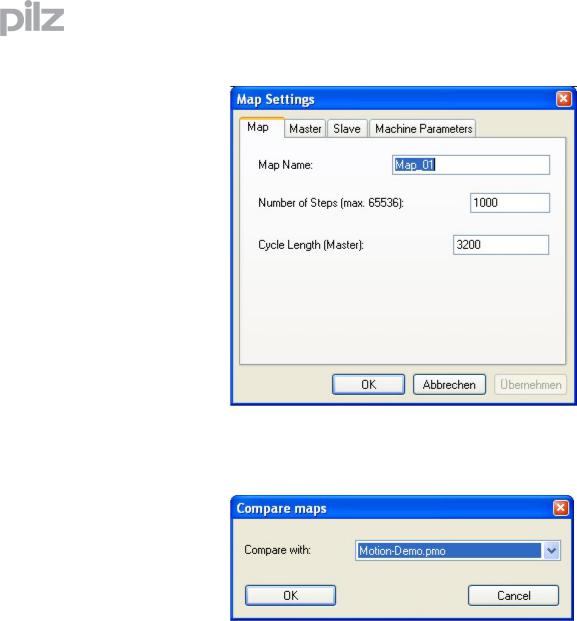
Map Settings |
Opens a dialogue box, where you can configure the map shape |
|
settings. |
Map variables |
Shows a dialogue box in which you can edit the map variables. |
Colours and Lines |
Adjustment of colours and lines for the motion view. |
Show comparison mapShow/Hide a further map in the motion view. Select a map in the following dialog to compare it to the current map.
7.2.3Menu "View"
Position |
Shows or hides the view „Position“. |
Velocity |
Shows or hides the view „Velocity“. |
Acceleration |
Shows or hides the view „Acceleration“. |
Jerk |
Shows or hides the view „Jerk“. |
Toolbar |
Shows or hides the toolbar. |
Status bar |
Shows or hides the status bar. |
Page 14 |
User Manual for PMotion |

7 PC based Motion Generator PMotion
7.2.4Menu "Create"
Create Map Table Creates the current map shape as a map table in a ptf-file (ptf = PMC
text file). With the text editor PEdit you can download this map to the controller.
Create Map Sequence Creates the current map shape as a map sequence in a ptf-file (ptf = PMC text file). With the text editor PEdit you can download this sequence to the controller. The internal Motion Generator on the controller is able to generate maps from this sequence during runtime.
Download map table Downloads the current map shape as a map table directly to the controller.
Download map sequence
Downloads the current map shape as a controller sequence directly to the controller. The internal Motion Generator on the system is able to generate maps from this sequence during runtime.
Import map
Active map from system
Imports the last map sequence to be executed (XS command) from the connected controller.
Map sequence from system
Imports a map from a map sequence saved on a controller.
Map sequence from file
Imports a map from a map sequence saved in a ptf file.
If values in the map sequence are defined as variables, you can enter a value for these during import for showing the map.
Export map as FB for SoftPLC
Exports the current map (map table or map sequence) as a function block for the system integrated Software PLC.
User Manual for PMotion |
Page 15 |

|
|
7 PC based Motion Generator PMotion |
7.2.5 |
Menu "Programs" |
|
|
PTerm |
Starts the terminal program PTerm. |
|
PDrive |
Starts the setup software PDrive. |
|
PScope |
Starts the scope function PScope. |
|
PEdit |
Starts the text editor PEdit. |
7.2.6Menu "Window"
New window |
Opens a further window for the current document. |
Cascade |
Arranges all the windows you are editing in a neat, cascaded, pile. |
Tile |
Tiles all the windows you are editing horizontally across the screen. |
Arrange icons |
Arranges all icons in the bottom area of the window. |
Page 16 |
User Manual for PMotion |

7 PC based Motion Generator PMotion
7.3Toolbar
With the toolbar you have direct access to important functions of the program.
Creates a new map.
Opens an existing map.
Saves the current map file.
Displays full pages of the current map before printing.
Prints the current map.
Selects the segment on the left side of the currently selected segment.
Selects the segment on the right side of the currently selected segment.
Inserts a new segment to the left side of the currently selected segment.
Splits a segment into two parts.
Adds a segment to the end of your map shape.
Deletes the currently selected segment.
Opens a dialogue bar on the left side of the view to configure the segment settings.
Creates a map table in a ptf-file (ptf = PMC text file).
Creates a map sequence in a ptf-file (ptf = PMC text file).
Downloads a map table to the controller.
Downloads a map sequence to the controller.
Starts the terminal program PTerm.
Starts the setup software PDrive.
Starts the scope function PScope.
Starts the text editor PEdit.
Opens the “About” dialog.
User Manual for PMotion |
Page 17 |
 Loading...