


19 588-03
PNOZ X6
4
D Betriebsanleitung
4
GB Operating instructions
4
F Manuel d'utilisation
Sicherheitsbestimmungen
• Das Gerät darf nur von Personen
installiert und in Betrieb genommen
werden, die mit dieser Betriebsanleitung
und den geltenden Vorschriften über
Arbeitssicherheit und Unfallverhütung
vertraut sind. Beachten Sie die VDEsowie die örtlichen Vorschriften, insbesondere hinsichtlich der Schutzmaßnahmen.
• Beim Transport, bei der Lagerung und im
Betrieb die Bedingungen nach EN 600682-6 einhalten (s. technische Daten).
• Durch Öffnen des Gehäuses oder
eigenmächtige Umbauten erlischt die
Gewährleistung.
• Montieren Sie das Gerät in einen
Schaltschrank; Staub und Feuchtigkeit
können sonst zu Beeinträchtigungen der
Funktionen führen.
• Sorgen Sie an allen Ausgangskontakten
bei kapazitiven und induktiven Lasten für
eine ausreichende Schutzbeschaltung.
• Die Sicherheitsfunktion muss mindestens
einmal im Monat ausgelöst werden.
4 E Instrucciones de uso
4 I Istruzioni per l`uso
4 NL Gebruiksaanwijzing
Safety Regulations
• The unit may only be installed and
operated by personnel who are familiar
with both these instructions and the
current regulations for safety at work and
accident prevention. Follow local
regulations especially as regards
preventative measures.
• Transport, storage and operating conditions should all conform to EN 60068-26 (s. technical data).
• Any guarantee is void following opening of
the housing or unauthorised
modifications.
• The unit should be panel mounted,
otherwise dampness or dust could lead to
functional impairment.
• Adequate protection must be provided on
all output contacts with capacitive and
inductive loads.
• The safety function must be triggered at
least once per month.
Conseils préliminaires
• La mise en oeuvre de l'appareil doit être
effectuée par une personne spécialisée
en installations électriques, en tenant
compte des prescriptions des différentes
normes applicables (NF, EN, VDE..),
notamment au niveau des risques
encourus en cas de défaillance de
l'équipement électrique.
• Respecter les exigences de la norme
EN 60068-2-6 lors du transport, du
stockage et de l'utilisation de l'appareil.
• Toutes interventions sur le boîtier
(ouverture du relais, échange ou
modification de composants, soudure
etc..) faites par l'utilisateur annulent la
garantie.
• Montez l'appareil dans une armoire
électrique à l'abri de l'humidité et de la
poussière.
• Assurez-vous du pouvoir de coupure des
contacts de sortie en cas de charges
inductives ou capacitives.
• La fonction de sécurité doit être activée
au moins une fois par mois.
Be
stimmungsgemäße Verwen-
dung
Der Schutztürwächter PNOZ X6 dient als
sichere Einrichtung zum Abschalten von
Maschinen und Anlagen. Das PNOZ X6 ist
bestimmt für den Einsatz in
• Schutztürüberwachungen
• NOT-AUS-Einrichtungen
• Sicherheitsstromkreisen nach VDE 0113
Teil 1 und EN 60204-1 (z. B. bei beweglichen Verdeckungen)
Gerätebeschreibung
Der Schutztürwächter ist in einem P-97Gehäuse untergebracht. Es stehen
verschiedene Varianten für den Betrieb mit
Wechselspannung und eine Variante für den
Betrieb mit 24 V Gleichspannung/Wechselspannung zur Verfügung.
Merkmale:
• Relaisausgänge:
3 Sicherheitskontakte (S), zwangsgeführt
• LED als Versorgungsspannungsanzeige
• LED für Kanal 1 und für Kanal 2
• Anschluß für Schutztürgrenztaster oder
NOT-AUS-Taster und Starttaster
• Betrieb mit und ohne Gleichzeitigkeitsüberwachung
• redundante Ausgangsschaltung
• ein- oder zweikanaliger Betrieb
• Rückführkreis zur Überwachung
externer Schütze
Das Schaltgerät erfüllt folgende Sicherheitsanforderungen:
• Der Schutztürwächter verhindert in
folgenden Fällen die Freigabe der Anlage:
Spannungsausfall, Ausfall eines Bauteils,
Spulendefekt, Leiterbruch, Erdschluß
• Überprüfung bei jedem Ein-Aus-Zyklus,
ob die Ausgangsrelais des Sicherheitsgerätes richtig öffnen und schließen
Intended Application
The PNOZ X6 can be used as a safety
device for stopping machines and
installations. The PNOZ X6 is for use in
• safety gate monitoring
• emergency stop installations and in
• safety circuits according to VDE 0113
Pt. 1 and EN 60204-1 (e.g. with movable
guards)
Description
The relay is enclosed in a P-97 housing.
There are different versions available for AC
operation and one for 24 VDC/AC operation.
Features:
• Relay outputs:
3 safety contacts (N/O), positive-guided
• LED for operating voltage
• LED for channel 1 and channel 2
• Connection for safety gate limit switch or
E-Stop button and reset button
• Can be operated with or without
simultaneity monitoring
• Output circuit is redundant
• Single or dual-channel operation
• Feedback control loop for monitoring
external contactors/relays
The relay complies with the following safety
requirements:
• The monitor prevents machine operation
in the following cases: power supply
failure, component failure, coil defect in a
relay, cable break, earth fault
• The correct opening and closing of the
safety function output relays is tested
automatically in each on-off cycle
- 1 -
Domaines d'utilisation
Le bloc de sécurité PNOZ X6 garantie de
manière sûre l'arrêt des machines et des
installations. Le PNOZ X6 est adapté pour :
• la surveillance de capots mobiles.
• les circuits d'arrêt d'urgence.
• les circuits de sécurité selon les normes
NF 79-130 et EN 60204-1 (ex.
protecteurs mobiles).
Description de l'appareil
Inséré dans un boîtier P-97, le relais PNOZ
X6 est disponible en différentes versions
pour les tensions alternatives et une version
en tension continue/alternative (24V).
Caractéristiques :
• Contacts de sortie :
3 contacts à fermeture de sécurité (F).
• LED d'indication présence tension.
• LED pour le canal 1 et pour le canal 2.
• Bornes de raccordement pour AU,
interrupteurs de position et poussoir de
validation
• Utilisation avec ou sans surveillance de
synchronisation temporelle.
• Sorties redondantes.
• Commande par un ou deux canaux.
• Boucle de retour pour l'auto-contrôle de
contacteurs externes.
Le relais répond aux exigences suivantes :
• Fonction de sécurité garantie en cas de :
défaillance tension, défaillance d'un
composant, défaillance bobine, défaut
soudure, défaut de masse
• Vérification à chaque cycle d'ouverture/
fermeture du bon fonctionnement des
relais internes.
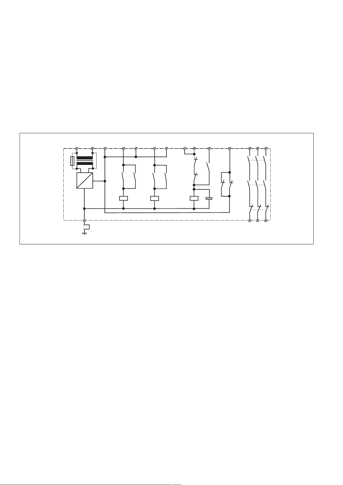
Funktionsbeschreibung
Der Schutztürwächter PNOZ X6 dient zur
Überwachung von Schutztüren an
Gefahrenstellen. Das Gerät reagiert auf
eine Unterbrechung in einem der Eingangskreise 1 oder 2 (Kanal 1 bzw. Kanal 2). Das
PNOZ X6 kann ein- oder zweikanalig
betrieben werden.
Sobald die Versorgungsspannung UB anliegt
und die Eingangskreise 1 und 2 geschlossen sind, ist das PNOZ X6 startbereit (LED
"Power" leuchtet). Wird der Startkreis
(Rückführkreis) geschlossen, gehen die
beiden Ausgangsrelais K1 und K2 in
Arbeitsstellung und die Sicherheitskontakte
13-14, 23-24 und 33-34 schließen. Die
LEDs "CH.1" und "CH.2" leuchten. Wird ein
Kontakt im Eingangskreis betätigt, fallen
beide Relais K1 und K2 ab. Die Sicherheitskontakte 13-14, 23-24 und 33-34 öffnen.
A2
A1
U
B
(L-)
(L+)
Function Description
The PNOZ X6 provides safety monitoring at
danger points. The unit reacts to an
interruption in the input circuit 1 or 2
(channel 1/channel 2), and is suitable for
single or dual-channel operation.
When the operating voltage UB is applied
and the input circuits 1 and 2 are closed, the
PNOZ X6 is ready for operation (LED
"Power" is illuminated). If the reset circuit
(feedback control loop) is closed, the two
output relays K1 and K2 energise and the
safety contacts 13-14, 23-24 and 33-34
close. The LEDs "CH.1" and "CH.2"
illuminate. If a contact in the input circuit is
activated, both relays K1 and K2 deenergise. The positive-guided safety
contacts 13-14, 23-24 and 33-34 open.
S12S11 13 23 33
S24S23
Y2
Y2Y1
Description du fonctionnement
Le bloc de sécurité PNOZ X6 sert à la
surveillance de protecteurs avec accès à
une zone dangereuse. Le relais réagit à une
ouverture dans un des canaux d'entrée 1
ou 2 (canal 1 ou canal 2). Le PNOZ X6 peut
être commandé par un ou deux canaux.
Dès que le relais est sous tension et que les
canaux d'entrée 1 et 2 sont fermés, le PNOZ
X6 est activé (la LED "Power" s'allume). Si le
circuit de réarmement (boucle de retour) est
fermé, les deux relais de sortie K1 et K2
passent en position de travail et les contacts
de sécurité 13-14, 23-24 et 33-34 se ferment.
Les LEDs "CH.1" et "CH.2" s'allument. Si l'un
des canaux d'entrée est ouvert, les deux
relais K1 et K2 retombent. Les contacts de
sécurité 13-14, 23-24 et 33-34 s'ouvrent.
Y4Y3
F1
G1
PNOZ X6
~
+
K1K3
=
K1
K3
K2
Fig. 1: Schematisches Schaltbild/Wiring diagram/Schéma interne
Sicherheitsfunktionen
Das Relais K3 prüft vor jedem Wiedereinschalten, ob die Ausgangsrelais zuvor vollständig abgefallen sind bzw. wieder anziehen. Im Fall einer Kontaktverschweißung
oder eines Drahtbruches ist ein Wiedereinschalten nicht möglich.
Betriebsarten
• Einkanaliger Betrieb: keine Redundanz im
Eingangskreis, Erdschlüsse im Tasterkreis werden erkannt
• Zweikanaliger Betrieb: redundanter Eingangskreis, Erdschlüsse werden erkannt
• Manueller Start
Gerät ist erst aktiv, wenn ein Starttaster
betätigt wird; der Starttaster muß in Reihe
zum Rückführkreis angeschlossen
werden.
• Manueller Start mit Überwachung: Gerät
ist erst aktiv, wenn der Starttaster betätigt
und wieder losgelassen wurde.
• Automatischer Start
- die Ausgangsrelais ziehen an, sobald
die Eingangskreise geschlossen sind
- für NOT-AUS-Stromkreise ist diese
Betriebsart nicht zulässig, da die
Anlage nach Spannungsausfall und wiederkehr selbsttätig anläuft.
Gleichzeitigkeit
• Bei NOT-AUS-Beschaltung darf die
Zeitdif-ferenz zwischen den beiden
Eingangskrei-sen max. 200 ms betragen.
• Bei Schutztürsteuerungen kann die
Zeitdif-ferenz durch Überbrücken von
Safety Functions
Each time the unit is switched on, relay K3
first checks if the output relays are fully deenergised. If a contact weld occurs or a
cable break is present, the unit cannot be
activated.
Operating Modes
• Single-channel operation: no redundancy
in the input circuit, earth faults in the
button circuit are detected
• Dual-channel operation: redundant input
circuit, earth faults and short-circuits are
detected
• Manual reset
Unit is not active until a reset button has
been pressed; the reset button must be
connected in series to the feedback
control loop.
• Manual reset with monitoring: Unit is only
activated, when the reset button ist
pressed and then released.
• Automatic reset
- the output contacts energise as soon
as the input circuit is closed
- automatic reset is not permitted for use
in emergency stop circuits as the
installation is activated independently
following a loss/return of supply voltage.
Simultaneity
• With emergency stop wiring, the time
delay between both the input circuits can
be a max. of 200 ms.
• With the safety gate control the time
delay can be infinite by linking Y3-Y4
Y3-Y4 auf unendlich verlängert werden.
K1
K3
K2
K2
K1 K2
K3 C1
K1
K2
K3
14 24 34
Fonctions de sécurité
Le relais K3 teste avant chaque remise
sous tension si les relais de sortie sont bien
retombés. En cas de soudage d'un contact
ou d'une coupure de fil, une remise sous
tension n'est plus possible.
Modes de fonctionnement
• Commande en 1 canal : pas de
redondance dans le circuit d'entrée, les
mises à la terre sont détectées.
• Commande en 2 canaux: circuit d'entrée
redondant, les mises à la terre sont
détectées.
• Réarmement manuel
Le relais n'est activé qu'après une
impulsion sur le poussoir de réarmement;
le poussoir de réarmement est câblé sur
les bornes Y1-Y2.
• Surveillance de circuit de réarmement
l
e relais n'est activé qu'après le
relâchement du poussoir de validation.
• Réarmement automatique
- les relais de sortie montent dès que les
canaux d'entrée sont fermés.
- Attention ! En cas de réarmement
automatique, la montée du relais ne doit
pas remettre votre installation sous
tension.
Désynchronisme
• En cas d'utilisation avec des poussoirs
AU, le désynchronisme entre les canaux
d'entrée doit être au max. de 200 ms.
• En cas d'utilisation comme surveillance
de protecteurs, le désynchronisme peut
être rendu infini en pontant les bornes Y3Y4.
- 2 -

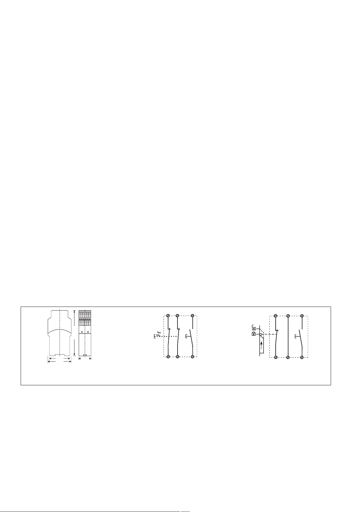
Montage
Das Sicherheitsschaltgerät muß in einen
Schaltschrank mit einer Schutzart von mind.
IP54 eingebaut werden. Zur Befestigung auf
einer Normschiene dient ein Rastelement auf
der Rückseite des Geräts.
Sichern Sie das Gerät bei Montage auf einer
senkrechten Tragschiene (35 mm) durch ein
Halteelement wie z. B. Endhalter oder
Endwinkel.
Installation
The safety relay must be panel mounted
(min. IP54). There is a notch on the rear of
the unit for DIN-Rail attachment.
If the unit is installed on a vertical mounting
rail (35 mm), ensure it is secured using a
fixing bracket such as end bracket.
Montage
Le relais doit être monté en armoire ayant
un indice de protection mini IP54. Sa face
arrière permet un montage sur rail DIN.
Immobilisez l'appareil monté sur un rail DIN
vertical (35 mm) à l'aide d'un élément de
maintien comme par ex. un support ou une
équerre terminale.
Inbetriebnahme
Beachten Sie bei der Inbetriebnahme:
• Vor die Ausgangskontakte eine
Sicherung (s. technische Daten)
schalten, um das Verschweißen der
Kontakte zu verhindern.
• Berechnung der max. Leitungslänge I
(Eingangskreis):
R
lmax
=
I
max
Rl / km
R
= max. Gesamtleitungswiderstand
lmax
(Eingangskreis)
Rl /km = Leitungswiderstand/km
• Leitungsmaterial aus Kupferdraht mit einer
Temperaturbeständigkeit von 60/75 °C
verwenden.
• Angaben im Kapitel „Technische Daten“
unbedingt einhalten.
Anschluß
• AC-Geräte: Betriebserde anschließen
• Versorgungsspannung an Klemmen A1 (+)
und A2 (-) anschließen.
• Eingangskreis
- Einkanalig: Öffnerkontakt von Auslöse-
element an S11 und S12 anschließen;
Brücke zwischen S12-S24 einlegen.
- Zweikanalig: Öffnerkontakte von
Auslöseelement an S11, S12 und an
S23, S24 anschließen.
• Startkreis
- Manueller Start: Startkontakt zwischen
Y1 und Y2 anschließen.
- Manueller Start mit Überwachung:
Startkontakt zwischen Y1-Y2, Y2-Y3
brücken.
- Automatischer Start: Brücke Y1-Y2
• Rückführkreis
Öffnerkontakte der zu überwachenden
Schütze am Rückführkreis Y1-Y2
oder, falls Startkontakt vorhanden, in Serie
dazu anschließen.
• nur bei Schutztürsteuerungen: wenn gewünscht, Überwachung der Gleichzeitigkeit durch Brücken von Y3-Y4 abschalten.
Ablauf
Das Gerät ist eingeschaltet, wenn
• die Versorgungssspannung anliegt (LED
"Power" leuchtet)
• die Eingangskreise geschlossen sind
• der Startkreis für mind. 300ims geschlos-
sen wird
Die Sicherheitskontakte 13-14, 23-24 und
33-34 sind geschlossen und die LEDs
"CH.1" und "CH.2" leuchten. Wird der
Eingangskreis geöffnet (NOT-AUS-Taster
betätigt), öffnen die Sicherheitskontakte 1314, 23-24 und 33-34.
Wieder aktivieren
• Eingangskreis schließen.
• Startkreis für mind. 300 ms schließen.
max
Operation
Please note for operation:
• To prevent contact welding, a fuse
should be connected before the
output contacts (see technical
details).
• Calculate the max. Cable runs I
circuit)
R
lmax
=
I
max
Rl / km
R
= Max. Total cable resistance
lmax
(Input circuit)
Rl /km = Cable resistance/km
• Use 60/75 °C copper wire only.
• Important details in the section
“Technical Data” should be noted and
adhered to.
Connection
• Connect the operating earth (AC units
only).
• Connect the operating voltage between
A1i(+) and A2 (-).
• Input circuit
- Single-channel: connect the N/C
contact from the trigger element to
S11 and S12; link between S12-S24
- Dual-channel: connect the N/C
contact from the trigger element to
S11, S12 and to S23, S24
• Reset circuit
- Manual reset: connect the reset
contact between Y1-Y2.
- Manual reset with monitoring: Connect
the reset contact to Y1-Y2, bridge Y2Y3.
- Automatic reset: linkY1-Y2
• Feedback control loop
Connect the N/C contact of the relay to
be monitored to the feedback control
loop Y1-Y2 or - if a reset contact is
available - connect in series to this.
• With safety gate control only: if required,
simultaneity monitoring can be switched
off by linking Y3-Y4.
To operate
The unit is activated when:
• the operating voltage is applied (LED
"Power" is illuminated)
• the input circuits are closed
• the start circuit is closed for a minimum
of 300 ms
The safety contacts 13-14, 23-24 and
33-34 are closed and the LED's "CH.1"
and "CH.2" illuminate. If the input circuit is
opened, the safety contacts 13-14, 23-24
and 33-34 open.
Reactivation
• Close the input circuit
• Close the reset circuit for a minimum of
300 ms.
- 3 -
max
(Input
Mise en oeuvre
Remarques préliminaires :
• Raccordez un fusible (voir les
caractéristiques techniques) avant les
contacts de sortie afin d’éliminer tout
risque de fusion.
• Calculer les longueurs de câblage max
I
(Circuits d’entrée):
max
R
lmax
=
I
max
Rl / km
R
= résistivité de câblage totale max.
lmax
(Circuits d’entrée)
Rl /km = résistivité de câblage/km
• Utiliser uniquement des fils de câblage en
cuivre 60/75 °C.
• Respecter les données indiquées dans le
chapitre "Caractéristiques techniques".
Branchement
• Relier la borne de terre (uniquement
appareils en AC).
• Ramener la tension d'alimentation (A1A2)
• Canaux d'entrée :
- Commande en 1 canal : câbler le
contact à ouverture de l'élément de
commande entre S11 et S12 ; pontage
des bornes S12-S24.
- Commande en 2 canaux : câbler les
contacts à ouverture de l'organe de
commande entre S11, S12 et S23, S24
• Circuit de réarmement :
- Réarmement manuel : câbler le
poussoir de validation entre les bornes
Y1 et Y2.
- Surveillance du circuit de réarmement:
câblage le poussoir de validation sur
Y1-Y2 et pontage des bornes Y2-Y3 .
- Réarmement automatique: ponter
Y1-Y2
• Boucle de retour
Câbler les contacts à ouverture des
contacteurs à surveiller dans la boucle de
retour ou, le cas échéant, les câbler en
série avec le poussoir de réarmement.
• uniquement en surveillance de
protecteur: inhibition du désynchronisme
entre les canaux d'entrée en pontant les
bornes Y3-Y4.
Mise en oeuvre
L'appareil est activé lorsque :
• la tension d'alimentation est appliquée
(LED "Power" s'allume).
• les canaux d'entrée sont fermés.
• le canal de validation est fermé pendant
au moins 300 ms.
Les contacts de sécurité 13-14, 23-24 et
33-34 se ferment et les LEDs "CH.1" et
"CH.2" s'allument. Si les canaux d'entrée
s'ouvrent, les contacts de sécurité 13-14,
23-24 et 33-34 s'ouvrent.
Réarmement
• Fermer les canaux d'entrée.
• Fermer le canal de validation au moins
300ims.
Anwendung
In allen Beispielen werden Erdschlüsse
erkannt. Fig. 2 und 3 sind Beispiele für
NOT-AUS-Stromkreise.
Schutztürsteuerungen (Fig. 4 - 8):
• Schutztürsteuerung 1 (Fig. 4)
- manueller Start mit S2
- einkanaliger Betrieb
- geeignet für Schutztüren, die nur zu
Wartungszwecken geöffnet werden
• Schutztürsteuerung 2 (Fig. 5)
- manueller Start mit S3
- zweikanaliger Betrieb
- geeignet für Schutztüren mit erhöhten
Sicherheitsanforderungen
• Schutztürsteuerung 3 (Fig. 6)
- mit automatischem Start nach dem
Schließen der Schutztüre
- Zeitdifferenz der Schaltpunkte beliebig
- zweikanaliger Betrieb
- geeignet für Schutztüren mit erhöhten
Sicherheitsanforderungen
• Schutztürsteuerung 4 (Fig. 7)
- wie Schutztürsteuerung 3, jedoch mit
Überwachung der zeitlichen Abfolge
der Grenztaster S1 u. S2 (Differenz t
der Schaltpunkte ca. 200 ms)
- geeignet für Schutztüren mit erhöhten
Sicherheitsanforderungen
• Schutztürsteuerung 5 (Fig. 8)
Überwachter Start: Das Gerät kann nur
gestartet werden, wenn der Starttaster
vor dem erneuten Betätigen gelöst war.
Der Rückführkreis dient zur Überwachung
externer Schütze, die zur Kontaktverstärkung oder Vervielfältigung verwendet
werden (Fig. 9). Eine Kombination mit den
Schaltungen nach Fig. 2 - 8 ist möglich.
g
Application
Earth faults are detected in all examples.
Fig. 2 and 3 are examples for Emergency
Stop circuits.
Safety gate control (Fig. 4 - 8):
• Safety gate control 1 (Fig. 4)
- manual reset with S2
- single-channel operation
- suitable for safety gates only opened
during maintenance
• Safety gate control 2 (Fig. 5)
- manual reset with S3
- dual-channel operation
- suitable for safety gates with high level
safety requirements
• Safety gate control 3 (Fig. 6)
- automatic reset following closure of the
safety gate
- time delay of the switchover point
adjustable
- dual-channel operation
- suitable for safety gates with high level
safety requirements
• Safety gate control 4 (Fig. 7)
- as safety gate control 3, but with
monitoring of the time sequence of the
limit switches S1 and S2 (delay tg of the
switchover points approx. 200 ms)
- suitable for safety gates with high level
safety requirements
• Safety gate control 5 (Fig. 8)
Monitored reset: the unit can only be
started if the reset button is released
before being pressed again
The feedback control loop is for the
monitoring external relays to increase the
number of contacts available (Fig. 9). A
combination with the wiring as in Fig. 2 - 8 is
possible.
Utilisation
Dans tous les exemples, les défauts de
masse sont détectés. Les figures 2 et 3
sont des exemples de circuits d'arrêt
d'urgence.
Dispositifs de verrouillage (fig. 4-8)
• Dispositif de verrouillage 1 (fig. 4) :
- mise en marche manuelle avec S2.
- commande par un canal.
- recommandé pour les capots mobiles
ouverts occasionnellement
(maintenance).
• Dispositif de verrouillage 2 (fig. 5) :
- mise en marche manuelle avec S3.
- commande par deux canaux.
- surveillance de protecteurs avec un
haut niveau de sécurité.
• Dispositif de verrouillage 3 (fig. 6) :
- mise en marche automatique après
fermeture des capots mobiles.
- désynchronisme infini entre la
fermeture des canaux d'entrée
- commande par deux canaux.
- surveillance de protecteurs avec un
haut niveau de sécurité.
• Dispositif de verrouillage 4 (fig. 7)
- idem que le dispositif de verrouillage 3,
avec surveillance du désynchronisme
entre la fermeture des canaux S1 et S2
(différence tg max. : 200 ms).
- surveillance de protecteurs avec un
haut niveau de protection.
• Dispositif de verrouillage 5 (fig. 8)
Surveillance du circuit de réarmement : le
circuit de réarmement doit être ouvert
avant une nouvelle impulsion pour réarmer
le relais.
La boucle de retour sert au contrôle de
contacteurs externes, qui sont utilisés pour
augmenter le pouvoir de coupure ou le
nombre de contacts (Fig. 9). Une combinaison avec les exemples 2 - 8 est
possible.
Das Gerät nur wie in den folgenden Only connect the unit as shown in the Câbler l'appareil uniquement comme
Abbildungen anschließen! following examples! l'indiquent les schémas suivants!
S11
S23
Y1
75 (2.95")
87 (3.42")
121 (4.76")
45 (1.77")
S1
S12
S24
S3
Y2
Fig. 2: Einkanaliger NOT-AUS (S1) Fig. 3: Zweikanaliger NOT-AUS (S1)
Single-channel E-Stop (S1) Dual-channel E-Stop (S1)
Arrêt d'urgence avec un canal (S1)
Arrêt d'urgence avec deux canaux (S1)
S11
S1
S12
Fig. 4: Schutztürsteuerung 1
Safety gate control 1
Dispositif de verrouillage 1
S12
S24
Y1
S2
Y2
- 4 -
S11
14
K4 K5
13
Y1 Y2
K4
K5
K5
K4
1L1
(1L+)
1L2
(1L-)
Y1
S11
Y1
Y3
S11
Y1
S24
S1
S12
S23
S2
S3
Y2
S12
S23
S24
S1
S12
S23
S2
Y4
Y2
S24
Fig. 5: Schutztürsteuerung 2 Fig. 6: Schutztürsteuerung 3 Fig. 7: Schutztürsteuerung 4
Safety gate control 2 Safety gate control 3 Safety gate control 4
Dispositif de verrouillage 2 Dispositif de verrouillage 3 Dispositif de verrouillage 4
S12
S23
S11
Y1
S1
S3
S2
Tür offen/
guard open/
porte ouverte
Tür geschlossen/
guard closed/
porte fermée
Betätigtes Element/
switch activated/
S24
Y2Y2Y3
élément actionné
Fig. 8: Schutztürsteuerung 5
Safety gate control 5
Dispositif de verrouillage 5
Fig. 9: Überwachung externer Schütze
Monitoring external relays
Contrôle de contacteurs externes
S1
S2
Y2
Fehler - Störungen
• Erdschluß
Die Versorgungsspannung bricht
zusammen und die Sicherheitskontakte
werden über eine elektronische Sicherung geöffnet. Nach Wegfall der Störungsursache und Abschalten der
Versorgungsspannung für ca. 1 Minute
ist das Gerät wieder betriebsbereit.
• Fehlfunktionen der Kontakte: Bei verschweißten Kontakten ist nach Öffnen
des Eingangskreises keine neue
Aktivierung möglich.
• LED "POWER" leuchtet nicht: Kurzschluß
oder Versorgungsspannung fehlt
Faults
• Earth fault
Supply voltage fails and the safety
contacts are opened via an electronic
fuse. Once the cause of the fault has
been removed and operating voltage is
switched off, the unit will be ready for
operation after approximately 1 minute.
• Contact failure: In the case of welded
contacts, no further activation is possible
following an opening of the input circuit.
• LED "POWER" is not illuminated if shortcircuit or the supply voltage is lost.
Erreurs - Défaillances
• Défaut de masse
La tension d’alimentation chute et les
contacts de sécurité sont ouverts par un
fusible électronique. Une fois la cause du
défaut éliminée et la tension d’alimentation
coupée, l’appareil est à nouveau prêt à
fonctionner après environ 1 minute.
• Défaut de fonctionnement des contacts
de sortie: en cas de soudage d’un
contact lors de l’ouverture du circuit
d’entrée, un nouvel réarmement est
impossible.
• LED "POWER" éteinte: tension
d'alimentation non présente ou courtcircuit interne.
- 5 -

Technische Daten/Technical data/Caractéristiques techniques
Versorgungsspannung UB/Operating Voltage/Tension d’alimentation
Spannungstoleranz/Voltage Tolerance/Plage de la tension d’alimentation
Leistungsaufnahme bei UB/Power Consumption/Consommation
Frequenzbereich/Frequency Range/Fréquence
Restwelligkeit/Residual Ripple/Ondulation résiduelle
Spannung und Strom an/Voltage, Current at //Tension et courant du
Eingangskreis/Input circuit/circuit d’entrée
Startkreis/reset circuit/circuit de réarmement UB DC
Startkreis/reset circuit/circuit de réarmement UB AC
Rückführkreis/feedback loop/boucle de retour U
Rückführkreis/feedback loop/boucle de retour UB AC
Ausgangskontakte nach EN 954-1/Output Contacts to EN 954-1/
Contacts de sortie d'après EN 954-1
Sicherheitskontakte (S), Kategorie 3/safety contacts N/O, category 3/
contacts de sécurité (F), catégorie 3
Gebrauchskategorie nach/Utilization category to/Catégorie d’utilisation d'après
EN 60947-4-1
AC1: 240 V
AC1: 400 V
DC 1: 24 V
EN 60947-5-1
AC 15: 230 V
DC13 (6 Schaltspiele/Min, 6 cycles/min, 6 manoeuvres/min): 24 V
Kontaktmaterial/Contact material/Matériau contact
Kontaktabsicherung extern nach/External Contact Fuse Protection/Protection des contacts
EN 60 947-5-1
Schmelzsicherung/Blow-out fuse/Fusibles
Sicherungsautomat/Safety cut-out/Dijoncteur
Max. Gesamtleitungswiderstand R
input circuits/ Résistance de câblage totale max. R
Eingangskreise/Max. overall cable resistance R
lmax
einkanalig/Single-channel/Commande par 1 canal
zweikanalig ohne Querschlußerkennung/Dual-channel without detection of shorts
across contacts/Commande par 2 canaux sans détection des court-circuits
Einschaltverzögerung/Switch-on delay/Temps de réarmement
Automatischer Start/Automatic reset/Réarmement automatique UB DC:
Automatischer Start/Automatic reset/Réarmement automatique UB AC
Automatischer Start nach Netz-Ein/Automatic reset after Power-ON / Réarmement
automatique après mise sous tension
Rückfallverzögerung /Delay-on De-Energisation /Temps de retombée
bei NOT-AUS/at E-STOP/en cas d'arrêt d'urgence
bei Netzausfall/with power failure/en cas de coupure d'alimentation UB DC
bei Netzausfall/with power failure/en cas de coupure d'alimentation UB AC
Wiederbereitschaftszeit bei max. Schaltfrequenz 1/s/recovery time at max. switching
frequency 1/s/temps de remise en service en cas de fréquence de commutation max. 1/s
nach NOT-AUS/after E-STOP/après l'arrêt d'urgence
nach Netzausfall/after power failure/après une coupure d'alimentation UB DC
nach Netzausfall/after power failure/après une coupure d'alimentation UB AC
Gleichzeitigkeit Kanal 1 und 2/Simultaneity channel 1 and 2/désynchronisme canal 1 et 2
Überbrückung bei Spannungseinbrüchen/Max. supply interruption before
de-energisation/tenue aux micro-coupures
EMV/EMC/CEM
Schwingungen nach/Vibration to/Vibrations d'après EN 60068-2-6
Klimabeanspruchung/Climate Suitability/Conditions climatiques
Luft- und Kriechstrecken/Airgap Creepage/Cheminement et claquage
Umgebungstemperatur/Operating Temperature/Température d’utilisation
Lagertemperatur/Storage Temperature/Température de stockage
Schutzart/Protection/Indice de protection
Einbauraum (z. B. Schaltschrank)/Mounting (eg. panel)/Lieu d'implantation (ex. armoire)
Gehäuse/Housing/Boîtier
Klemmenbereich/Terminals/Bornes
DC
B
circuits d'entrée
lmax
lmax
AC: 24 V/42 V/48 V/110-120 V/230-240 V
DC: 24 V
-15 ... +10 %
UB DC: 2,0 W
UB AC: 6,5 VA
AC: 50 ... 60 Hz
DC: 160 %
24 V DC, 50 mA
24 V DC, 55 mA
24 V DC, 100 mA
24 V DC, 55 mA
24 V DC, 100 mA
3
I
: 0,01 A, I
min
I
: 0,01 A, I
min
I
: 0,01 A, I
min
I
: 5,0 A
max
I
: 7,0 A
max
: 8,0 A, P
max
: 5,0 A, P
max
: 8,0 A, P
max
: 2000 VA
max
: 2000 VA
max
: 200 W
max
AgSnO2+ 0,2 µm Au
10 A flink/quick acting/rapide oder /or/ou
6 A träge/slow acting/normeaux
24 V AC/DC: 6 A Charakteristik /
Characteristic/Caractéristiques B/C
100 Ohm
200 Ohm
typ. 250 ms, max. 350 ms
typ. 270 ms, max. 370 ms
typ. 260 ms, max. 350 ms
typ. 15 ms, max.: 30 ms
typ. 110 ms, max. 160 ms
typ. 150 ms, max. 200 ms
50 ms
200 ms
250 ms
200 ms / ∞
20 ms
EN 61000-6-2, EN 60947-5-1
Frequenz/Frequency/Fréquences:10-55Hz
Amplitude/Amplitude/Amplitude: 0,35 mm
EN 60068-2-78
EN 60947-1
-10 ... +55 °C
-40 ... +85 °C
IP54
IP40
IP20
- 6 -

Gehäusematerial/housing material/matériau du boîtier
Gehäuse/Housing/Boîtier
Front/front panel/face avant
Max.Querschnitt des Außenleiters (Schraubklemmen)/Max. cable cross section (screw
terminals)/Capacité de raccordement (borniers à vis)
1 Leiter, flexibel/1 core, flexible/1 conducteur souple
2 Leiter gleichen Querschnitts, flexibel mit Aderendhülse, ohne Kunststoffhülse/
2 core, same cross section flexible with crimp connectors, without insulating sleeve/
2 conducteurs de même diamètre souple avec embout, sans chapeau plastique
ohne Aderendhülse oder mit TWIN-Aderendhülse/without crimp connectors or with TWIN
crimp connectors/souple sans embout ou avec embout TWIN
Anzugsdrehmoment für Schraubklemmen/Torque setting for screw terminals/
couple de serrage (borniers à vis)
Abmessungen (Schraubklemmen) H x B x T/Dimensions H x W x D (screw terminals)/
Dimensions (borniers à vis) H x P x L
Einbaulage/Fitting Position/Position de montage
Gewicht/Weight/Poids
PPO UL 94 V0
ABS UL 94 V0
0,20 ... 4,00 mm2/24-10 AWG
0,20 ... 2,50 mm2/24-14 AWG
0,20 ... 2,50 mm2/24-14 AWG
0,6 Nm
87 x 45 x 121 mm
beliebig/any/indifférente
295 g (UB DC)
390 g (UB AC)
Es gelten die 09/04 aktuellen Ausgaben der
Normen.
The version of the standards current at 09/
04 shall apply.
Se référer à la version des normes en
vigeur au 09/04.
Max. Dauerstrom bei gleichzeitiger Belastung mehrerer Kontakte/Max. continuous current with several contacts under
load simultaneously/Courant permanent max. en cas de charge sur plusieurs contacts (AC1, DC1)
Anzahl der Kontakte/number of contacts/nombre des contacts 3 2 1
Imax (A) pro Kontakt bei Versorgungsspannung AC/per contact
with operating voltage AC/par contact pour tension d’alimentation AC 6,0 7,3 8,0
Imax (A) pro Kontakt bei Versorgungsspannung DC/per contact
with operating voltage DC/par contact pour tension d’alimentation DC 8,0 8,0 8,0
Um ein Versagen der Geräte zu verhindern,
an allen Ausgangskontakten für eine ausreichende Funkenlöschung sorgen. Bei
kapazitiven Lasten sind eventuell auftretende Stromspitzen zu beachten. Bei DCSchützen Freilaufdioden zur Funkenlöschung einsetzen, um die Lebendauer der
To prevent failure of the unit, all output
contacts should be fused adequately. With
capacative loads, possible current peaks
are to be avoided. With DC contactors/
relays use suitable spark suppression to
ensure extended life of the contactors/
relays.
Prévoir un dispositif d’extinction d’arc sur
les contacts de sortie pour éviter un
éventuel disfonctionnement du relais.
Tenir compte des pointes d’intensité en cas
de charge capacitive. Equiper les
contacteurs DC de diodes de roue libre .
Schütze zu erhöhen.
Lebensdauer der Ausgangsrelais/Service Life of Output relays/Durée de vie des relais de sortie
10
AC1: 230 V
DC1: 24 V
DC13: 24 V
1
Courant coupé (A)
Nennbetriebstrom (A)
Nominal operating current (A)
0.1
10 100 1000 10000
Schaltspielzahl x 10
Nombre de manvres x 10
AC15: 230 V
Cycles x 10
3
AC1: 400 V
3
3
- 7 -

Abmessungen in mm (")/Dimensions in mm (")/Dimensions en mm (")
121 (4.76")
75 (2.95")
87 (3.42")
EG-Konformitätserklärung:
Diese(s) Produkt(e) erfüllen die Anforderungen der Richtlinie 2006/42/EG über
Maschinen des europäischen Parlaments
und des Rates.
Die vollständige EG-Konformitätserklärung
finden Sie im Internet unter www.pilz.com
Bevollmächtigter: Norbert Fröhlich,
Pilz GmbH & Co. KG, Felix-Wankel-Str. 2,
73760 Ostfildern, Deutschland
45 (1.77")
EC Declaration of Conformity:
This (these) product(s) comply with the
requirements of Directive 2006/42/EC of the
European Parliament and of the Council on
machinery.
The complete EC Declaration of Conformity
is available on the Internet at www.pilz.com
Authorised representative: Norbert Fröhlich,
Pilz GmbH & Co. KG, Felix-Wankel-Str. 2,
73760 Ostfildern, Germany
Déclaration de conformité CE :
Ce(s) produit(s) satisfait (satisfont) aux
exigences de la directive 2006/42/CE
relative aux machines du Parlement
Européen et du Conseil.
Vous trouverez la déclaration de conformité
CE complète sur notre site internet
www.pilz.com
Représentant : Norbert Fröhlich,
Pilz GmbH & Co. KG, Felix-Wankel-Str. 2,
73760 Ostfildern, Allemagne
A
Pilz Ges.m.b.H., ✆ 01 7986263-0, Fax: 01 7986264, E-Mail: pilz@pilz.at
safety@pilz.com.au
E-Mail: pilz@pilzbr.com.br
✆
74436332, Fax: 74436342, E-Mail: pilz@pilz.dk
Electronic,
pilz.fi@pilz.dk
Fax: 031 789555, E-Mail: info@pilz.it
✆
045 471-2281, Fax: 045 471-2283, E-Mail: pilz@pilz.co.jp
Ltd.,
info@mx.pilz.com
352, E-Mail: t.catterson@pilz.co.nz
✆
021 62494658, Fax: 021 62491300,
Office,
SE
Pilz Skandinavien K/S, ✆ 0300 13990, Fax: 0300 30740, E-Mail: pilz.se@pilz.dk
✆
0224 2360180, Fax: 0224 2360184, E-Mail: pilz.tr@pilz.de
info@pilzusa.com
www
www.pilz.com
D
Pilz GmbH & Co. KG, Sichere Automation, Felix-Wankel-Straße 2, 73760 Ostfildern, Deutschland, ✆ +49 711 3409-0, Fax: +49 711 3409-133,
E-Mail: pilz.gmbh@pilz.de
B L
✆
03 88104000, Fax: 03 88108000, E-Mail: siege@pilz-france.fr
GB
Pilz Belgium, ✆ 09 3217570, Fax: 09 3217571, E-Mail: info@pilz.be
CH
Pilz lndustrieelektronik GmbH, ✆ 062 88979-30, Fax: 062 88979-40, E-Mail: pilz@pilz.ch
Pilz Automation Technology, ✆ 01536 460766, Fax: 01536 460866, E-Mail: sales@pilz.co.uk
IRL
E
Pilz lndustrieelektronik S.L., ✆ 938497433, Fax: 938497544, E-Mail: pilz@pilz.es
Pilz Ireland Industrial Automation, ✆ 021 4346535, Fax: 021 4804994, E-Mail: sales@pilz.ie
MEX
NL
Pilz Nederland, ✆ 0347 320477, Fax: 0347 320485, E-Mail: info@pilz.nl
P
Pilz Industrieelektronik S.L., ✆ 229407594, Fax: 229407595, E-Mail: pilz@pilz.es
E-Mail: sales@pilz.com.cn
USA
AUS
Pilz Australia, ✆ 03 95446300, Fax: 03 95446311, E-Mail:
BR
Pilz do Brasil, ✆ 11 4337-1241, Fax: 11 4337-1242,
DK
FIN
Pilz Skandinavien K/S, ✆ 09 27093700, Fax: 09 27093709, E-Mail:
Pilz de Mexico, S. de R.L. de C.V., ✆ 55 5572 1300, Fax: 55 5572 4194, E-Mail:
NZ
ROK
Pilz Automation Safety L.P., ✆ 734 354-0272, Fax: 734 354-3355, E-Mail:
Pilz Korea, ✆ 031 8159541, Fax: 031 8159542, E-Mail: info@pilzkorea.co.kr
TR
Pilz Elektronik Güvenlik Ürünleri ve Hizmetleri Tic. Ltd. ¸Sti.,
I
Pilz ltalia Srl, ✆ 031 789511,
Pilz New Zealand, ✆ 09- 6345-350, Fax: 09-6345-
PRC
Pilz China Representative
- 8 -
Pilz Skandinavien K/S,
F
Pilz France
J
Pilz Japan Co.,
06 Printed in Germany
Originalbetriebsanleitung/Original instructions/Notice originale
19 588-02-2010-

19 588-03
PNOZ X6
4 E Instrucciones de uso
4 I Istruzioni per l`uso
4 NL Gebruiksaanwijzing
Normas de seguridad
• El dispositivo debe ser instalado y
puesto en funcionamiento sólo por
personas que tengan experiencia con
estas instrucciones de uso y con las
normativas de seguridad del trabajo y
prevención de accidentes vigentes.
Tener en cuenta las normativas VDE,
como también las normativas locales,
especialmente en lo concerniente a
medidas de protección.
Para transporte, almacenaje y en el
funcionamiento, se deben cumplir las
normas según EN 60068-2-6 (v. datos
técnicos).
• La apertura de la carcasa o modificaciones por cuenta propia extingue toda
garantía.
• Instale el dispositivo en un armario de
distribución; polvo y humedad pueden
conducir, de lo contrario, a una merma
de las funciones.
• Procúrese una conexión de protección
adecuada, en todos los contactos de
salida sometidos a cargas capacitivas e
inductivas.
• La función de seguridad debe ejecutarse
por lo menos una vez al mes.
Aplicación correcta
El supervisor de puerta protectora PNOZ
X6 sirve como dispositivo seguro para la
desconexión de máquinas e instalaciones.
El PNOZ X6 está destinado para ser usado
en
• Supervisión de puertas protectoras
• Dispositivos para parada de emergencia
• Circuitos eléctricos de seguridad según
VDE 0113 parte 1 y EN 60204-1 (p. ej.,
para cubiertas móviles)
Norme di sicurezza
• Il dispositivo deve essere installato e
messo in funzione solo da persone a
conoscenza delle presenti istruzioni per
l’uso e delle norme antinfortunistiche e di
sicurezza del lavoro vigenti. Si devono
inoltre rispettare le norme VDE, nonché
le norme locali, soprattutto per quanto
riguarda gli interventi di sicurezza.
Per il trasporto, l’immagazzinamento ed il
funzionamento, rispettare le norme EN
60068-2-6 (vedere i dati tecnici).
• In caso di apertura della custodia o di
modifiche non autorizzate, non sarà
riconosciuta alcuna garanzia.
• Montare il dispositivo in un armadio
elettrico, perché la polvere e l’umidità
potrebbero comprometterne il funzionamento.
• In caso di carichi capacitivi ed induttivi,
assicurare una adeguata protezione per
tutti i contatti di uscita.
• La funzione di sicurezza deve essere
attivata almeno una volta al mese.
Uso previsto
Il controllo riparo mobile PNOX X6 è un
dispositivo sicuro per il disinserimento di
macchine ed impianti.
Il PNOZ X6 è previsto per l’impiego nei
• Controlli di ripari mobili
• Dispositivi di arresto di emergenza
• Circuiti elettrici di sicurezza secondo
VDE 0113 parte 1 ed EN 60204-1 (per
es. per ripari mobili)
Veiligheidsvoorschriften
•
Het apparaat mag uitsluitend worden
geïnstalleerd en in bedrijf genomen door
personen die vertrouwd zijn met deze
gebruiksaanwijzing en met de geldende
voorschriften op het gebied van arbeidsveiligheid en ongevallenpreventie. Neemt
u de van toepassing zijnde Europese
richtlijnen en de plaatselijke voorschriften
in acht, in het bijzonder m.b.t. tot de
veiligheidsmaatregelen.
• Neemt u bij transport, opslag en in bedrijf
de richtlijnen volgens EN 60068-2-6 in
acht (zie technische gegevens).
• Het openen van de behuizing of het
eigenmachtig veranderen van de
schakeling heeft verlies van de garantie
tot gevolg.
• Monteert u het apparaat in een
schakelkast. Stof en vochtigheid kunnen
anders de werking nadelig beïnvloeden.
• Zorgt u bij capacitieve of inductieve
belasting van de uitgangscontacten voor
adequate contactbeschermingsmaatregelen.
• De veiligheidsfunctie moet ten minste
een keer per maand geactiveerd
worden.
Toegelaten applicaties
Het hekbewakingsrelais PNOZ X6 dient als
veiligheidsvoorziening voor het afschakelen
van machines en installaties.
De PNOZ X6 is bestemd voor gebruik in
• hekbewaking
• noodstopvoorzieningen
• veiligheidscircuits volgens VDE 0113 deel
1en EN 60204-1 (b.v. bij beweegbare
afschermingen)
Descripción del dispositivo
El supervisor de puerta protectora está
alojado en una carcasa P-97. Hay
disponibles diferentes versiones para el
funcionamiento con corriente alterna y una
variante para el funcionamiento con 24 V
corriente contínua/alterna.
Características:
• Salidas de relés:
3 contactos de seguridad (NA), de guía
forzosa
• LED como indicador de tensión de
alimentación
• LED para canal 1 y canal 2
• Conexión para final de carrera de
seguridad de puerta protectora o
pulsador de parada de emergencia y
pulsador de rearme
• Funcionamiento con y sin supervisión
de simultaneidad
• Conexión redundante de la salida
• Funcionamiento mono o bicanal
• Circuito de realimentación para
supervisión de contactores externos.
El dispositivo cumple los siguientes
requisitos de seguridad:
• El supervisor de puerta protectora
impide la habilitación de la instalación en
los siguientes casos:
Caída de tensión, avería de una pieza,
bobina defectuosa, rotura de conductor,
contacto a tierra
Descrizione del dispositivo
Il controllo riparo mobile è inserito in una
custodia P-97. Sono disponibili diverse
vari-anti per il funzionamento con tensione
alter-nata ed una variante per il funzionamento con tensione continua/alternata di
24 V.
Caratteristiche:
• Uscite relè:
3 contatti di sicurezza (NA), a
conduzione forzata
• LED indicatore per la tensione di
alimentazione
• LED indicatore per canale 1 e canale 2
• Collegamento per finecorsa riparo
mobile o pulsante di arresto di
emergenza e pulsante di start
• Funzionamento con o senza controllo
simultaneità
• Collegamento di uscita ridondante
• Funzionamento monocanale o bicanale
• Circuito di readback per il controllo dei
relè esterni
Il dispositivo elettrico è conforme ai
seguenti requisiti di sicurezza:
• Nei seguenti casi il controllo del riparo
mobile impedisce lil riavvio dell’impianto:
interruzione della tensione, avaria di un
componente, difetto di una bobina,
interruzione di un conduttore,
dispersione verso terra
- 9 -
Apparaatbeschrijving
Het hekbewakingsrelais is in een P-97behuizing ondergebracht. Er zijn verschillende varianten voor wisselspanning en één
variant voor 24 V gelijkspanning/
wisselspanning beschikbaar.
Kenmerken:
• Relaisuitgangen:
3 veiligheidscontacten (M), mechanisch
gedwongen
• LED voor voedingsspanning
• LED voor kanaal 1 en kanaal 2
• Aansluitmogelijkheid voor deurcontacten of
noodstopknoppen en de startknop
• Bedrijf met en zonder
gelijktijdigheidsbewaking
• Redundante uitgangsschakeling
• Een- of tweekanalig bedrijf
• Terugkoppelcircuit voor de bewaking van
externe magneetschakelaars
Het relais voldoet aan de volgende
veiligheidseisen:
• Het hekbewakingsrelais verhindert in de
volgende gevallen dat de installatie vrijgegeven wordt: uitvallen van de spanning,
uitvallen van een component, defect in
een spoel, kabelbreuk, aardsluiting

• Verificación cíclica en cada ciclo de
marcha/parada, si los relés de salida del
dispositivo de seguridad abren y cierran
correctamente
Descripción funcional
El supervisor de puerta protectora PNOZ
X6 sirve para la supervisión de puertas
protectoras en lugares peligrosos. El
dispositivo reacciona a una interrupción en
uno de los circuitos de entrada 1 ó 2 (canal
1 o bien canal 2). El PNOZ X6 puede
hacerse funcionar mono o bicanal.
Apenas se aplica la tensión de alimentación
UB y se cierran los circuitos de entrada 1 y 2,
está el PNOZ X6 listo para funcionar (el LED
“Power”
se ilumina). Si se cierra el circuito
de rearme (circuito de realimentación), los
relés de salida K1 y K2 pasan a la posición
de trabajo y se cierran los contactos de
seguridad 13-14, 23-24 y 33-34. Los LEDs
“
CH1” y “CH2” se iluminan. Cuando se
acciona un contacto en el circuito de
entrada, se desactivan ambos relés K1 y
K2. Los contactos de seguridad 13-14, 2324 y 33-34 se abren.
A2
A1
U
B
(L-)
(L+)
• Ad ogni ciclo di inserimentodisinserimento viene controllato se i relè
di uscita del dispositivo di sicurezza
aprono e chiudono correttamente
Descrizione del funzionamento
Il dispositivo PNOZ X6 serve per
controllare i ripari mobili di zone pericolose.
Il dispositivo reagisce all’interruzione in uno
dei circuiti di ingresso 1 o 2 (canale 1 o 2).
Il PNOZ X6 può funzionare nel modo
monocanale o bicanale.
Non appena viene applicata la tensione di
alimentazione UB ed i circuiti di ingresso 1 o
2 sono chiusi, il PNOZ X6 è pronto per il
funzionamento (LED «Power» acceso). Se il
circuito di start (circuito di retroazione) viene
chiuso, i due relè di uscita K1 e K2
passano nella posizione di lavoro ed i
contatti di sicurezza 13-14, 23-24 e 33-34
si chiudono. I LED «CH.1» e «CH.2» sono
accesi. Se viene attivato un contatto nel
circuito di ingresso, i due relè K1 e K2 si
diseccitano. I contatti di sicurezza 13-14,
23-24 e 33-34 si aprono.
•
Bij elke aan/uit-cyclus wordt automatisch
getest of de uitgangsrelais van de
veiligheidsvoorziening correct openen en
sluiten
Functiebeschrijving
De PNOZ X6 dient voor de veilige hekbewaking op gevaarlijke plaatsen. Het apparaat
reageert op een onderbreking in een van de
ingangscircuits 1 of 2 (kanaal 1 resp. kanaal
2). De PNOZ X6 kan een- of tweekanalig
gebruikt worden.
Zodra de voedingsspanning U
keld is en de ingangscircuits 1 en 2 gesloten
zijn, is de PNOZ X6 bedrijfsklaar (LED
„Power“ licht op). Als het startcircuit
(terugkoppelcircuit) gesloten wordt, worden
de beide uitgangsrelais K1 en K2 bekrachtigd en de veiligheidscontacten 13-14, 23-24
en 33-34 sluiten. De LED’s „CH.1“ en
„CH.2“ lichten op. Als een contact in het
ingangscircuit bekrachtigd wordt, vallen
beide relais K1 en K2 af. De veiligheidscontacten 13-14, 23-24 en 33-34 gaan
open.
S12S11 13 23 33
S24S23
Y2
Y2Y1
Y4Y3
ingescha-
B
F1
G1
PNOZ X6
~
+
K1K3
=
K1
K2
K3
K2
Fig. 1: Esquema de conexión eléctrica/Schema di collegamento/Intern schema
Funciones de seguridad
El relé K3 verifica antes de conectar de
nuevo, si previamente los relés de salida
están completamente desactivos o bien otra
vez activos. En caso de contactos soldados
por sobrecalentamiento o una rotura del hilo
conductor, no es posible una reconexión.
Modos de funcionamiento
• Funcionamiento monocanal: No hay
redundancia en el circuito de entrada,
son reconocidos cortocircuitos en el
circuito del pulsador.
• Funcionamiento bicanal: Circuito de
entrada redundante, son reconocidos
los cortocircuitos.
• Rearme manual
El dispositivo está recién activo, cuando
se acciona un pulsador de rearme; el
pulsa-dor de rearme debe estar
conectado en serie al circuito de
realimentación.
• Rearme manual con supervisión: El
dispositivo está recién activado, cuando
el pulsador de rearme es accionado y
soltado nuevamente.
• Rearme automático
- Los relés de salida se excitan, tan
pronto como se cierran los circuitos
de entrada
- Este modo de funcionamiento no está
permitido para circuitos eléctricos de
parada de emergencia, ya que la
Funzioni di sicurezza
Prima di ogni reinserimento il relè K3
verifica se in precedenza i relè di uscita si
erano completamente diseccitati o se ora
si chiudono. In caso di contatti saldati o di
interruzione di un conduttore, il reinserimento è impossibile.
Modalità operative
• Funzionamento monocanale: nessuna
ridondanza nel circuito di ingresso,
vengono rilevate le dispersioni verso
terra nel circuito del pulsante.
• Funzionamento bicanale: circuito di
ingresso ridondante, vengono rilevate le
dispersioni verso terra
• Start manuale
Il dispositivo è attivo solo dopo che è
stato azionato un pulsante di start, il
quale deve essere collegato in serie con
il circuito di retroazione.
• Start manuale controllato: Il dispositivo è
attivo solo dopo che è stato azionato e
rilasciato il pulsante di start.
• Start automatico:
- i relè di uscita si chiudono non appena
i circuiti di ingresso sono chiusi
- per i circuiti elettrici di arresto di
emergenza, questa modalità operativa
non è consentita, perché dopo
l’interruzione ed il ripristino della
tensione l’impianto si riavvia automati-
camente
instalación arranca automáticamente
después de una interrupción y vuelta
de la tensión
- 10 -
K1
K2
K3 C1
K1
K3
K1 K2
K2
K3
14 24 34
Veiligheidsfuncties
Relais K3 controleert elke keer voordat
weer wordt ingeschakeld, of de uitgangsrelais van tevoren volledig afgevallen zijn
dan wel weer opkomen. In geval van
verkleefde contacten of een draadbreuk is
opnieuw inschakelen niet mogelijk.
Bedrijfsmodi
•
Eenkanalig bedrijf: geen redundantie in
het ingangscircuit, aardsluitingen in het
ingangscircuit worden gedetecteerd
• Tweekanalig bedrijf: redundant ingangscircuit, aardsluitingen worden
gedetecteerd
• Handmatige start
Apparaat is pas actief, als een startknop
bediend wordt; de startknop moet in serie
met het terugkoppelcircuit aangesloten
worden.
• Handmatige start met bewaking:
Apparaat is pas actief als de startknop
bediend en weer losgelaten is.
• Automatische start:
- de uitgangsrelais komen op, zodra de
ingangscircuits gesloten zijn
- voor noodstopcircuits is deze bedrijfs-
modus niet toegelaten, omdat de
installatie na uitvallen en terugkeren
van de spanning automatisch aanloopt

Simultaneidad
• En conexionados de parada de emergencia, la diferencia temporal entre ambos
circuitos de entrada, puede ascender
como máximo a 200 ms.
• En controles de puerta protectora, puede
prolongarse la diferencia temporal a
infinito, mediante el puenteado de Y3-Y4.
Simultaneità
• Nel cablaggio dell’arresto di emergenza
la differenza di tempo tra i due circuiti di
ingresso non deve essere superiore a
max 200 ms.
• Nei controlli dei ripari mobili, la differenza
di tempo può essere prolungata all’infinito
ponticellando Y3-Y4.
Gelijktijdigheid
•
Bij noodstopschakeling mag het tijdsverschil tussen de beide ingangscircuits
max. 200 ms bedragen
• Bij hekbewaking kan het tijdsverschil tot
oneindig verlengd worden door Y3-Y4 te
verbinden
Montaje
El dispositivo de seguridad debe montarse en
un armario e distribución con una protección
mín. de IP54. Para fijación sobre una guía DIN
dispone de un elemento de enclavamiento en
el lado posterior del dispositivo. Asegu-re el
interface en el montaje sobre una guía de
sujeción (35 mm) vertical mediante un
elemento de fijación como por ej. con un tope
terminal o un ángulo de cierre.
Puesta en marcha
Tenga en cuenta durante la puesta en
marcha:
• Protección de los contactos de salida
por fusibles (v. datos técnicos) para
evitar la soldadura de los mismos.
• Máx. longitudes de cable I
entrada)
R
lmax
=
I
max
Rl / km
R
= Resistencia de cable maxima total
lmax
(Circuito de entrada)
Rl /km = Resistencia de cable / km
• Emplear sólo conductores de cobre con
resistencia a la temperatura de 60/75 °C.
• Respetar necesariamente las indicaciones
del capítulo “Datos Técnicos”.
Conexión
• Dispositivos AC: Conectar la tierra funcional
• Conectar la tensión de alimentación a los
bornes A1 (+) y A2 (-).
• Circuito de entrada
- Monocanal: Conectar el contacto
normalmente cerrado del elemento
disparador en S11 y S12; poner un
puente entre S12-S24.
- Bicanal: Conectar los contactos normal-
mente cerrados del elemento
disparador en S11, S12 y en S23, S24.
• Circuito de rearme
- Rearme manual: Conectar el contacto de
rearme entre Y1 e Y2.
- Rearme manual con supervisión:
Puentear el contacto de rearme entre Y1Y2, Y2-Y3.
- Rearme automático: Puente entre Y1-Y2
• Circuito de realimentación
Conectar en el circuito de realimentación
Y1-Y2 los contactos normalmente cerrados
de los contactores a supervisar, o en el
caso que exista un contacto de rearme,
conectarlo en serie con ese fin.
• Solamente en control de puerta
protectora: cuando se desea,
desconectar la supervisión de
simultaneidad, mediante puenteado de
Y3-Y4.
Desarrollo
El dispositivo está conectado, cuando
• Se ha aplicado la tensión de alimentación
(se ilumina el LED “Power”)
• Están cerrados los circuitos de entrada
• El circuito de rearme es cerrado por lo
menos 300ms.
(Circuito de
max
Montaggio
L’apparecchio elettrico di sicurezza deve
essere montato in un armadio elettrico con
un tipo di protezione di min. IP54. Per il
fissaggio su guida DIN è previsto un
elemento di incastro sul lato posteriore
dell’apparecchio.
Per il montaggio del dispositivo su una
guida DIN (35 mm) usando un elemento di
blocco, per es. un supporto terminale.
Messa in funzione
Per la messa in funzione rispettare
quanto segue:
• A monte dei contatti di uscita si deve
collegare un fusibile (vedere i dati
tecnici) per impedire la saldatura tra
i contatti stessi.
• Lunghezze max dei cavi I
entrata):
R
lmax
=
I
max
Rl / km
R
= Resistenza max dei cavi totale
lmax
(circuito di entrata)
Rl /km = Resistenza dei cavi / km
• Usare conduttori di rame con una
resistenza termica di 60/75 °C.
• Rispettare assolutamente le indicazioni
riportate nel capitolo «Dati tecnici».
Collegamento
• Dispositivi AC: collegare la massa
elettrica
• Applicare la tensione di alimentazione ai
morsetti A1 (+) e A2 (-).
• Circuito di ingresso
- Monocanale: collegare il contatto NC a
S11 e S12, ponticellare S12-S24.
- Bicanale: collegare i contatti NC a S11,
S12 e a S23, S24.
• Circuito di start:
- Start manuale: collegare il contatto di
start tra Y1 e Y2.
- Start manuale controllato: ponticellare
il contatto di start tra Y1-Y2, Y2-Y3.
- Start automatico: ponticello tra Y1-Y2
• Circuito di retroazione
Collegare i contatti NC dei relè da
controllare al circuito di retroazione Y1Y2, oppure in serie al contatto di start se
esistente.
• Solo per controlli di ripari mobili:
eventualmente disinserire il controllo
della simultaneità ponticellando Y3-Y4.
Procedura
Il dispositivo è inserito se
• La tensione di alimentazione è applicata
(LED «Power» acceso)
• I circuiti di ingresso sono chiusi
• Il circuito di start viene chiuso per
almeno 300 ms
max
(circuito di
Montage
Het veiligheidsrelais dient gemonteerd te
worden in een schakelkast die minimaal
voldoet aan beschermingsgraad IP54.
Bevestiging op een DIN-rail is mogelijk via
de daarvoor bestemde relaisvoet. Bij montage op een verticale draagrail (35 mm) moet
het apparaat worden vastgezet met een
eindsteun.
Ingebruikname
Neemt u bij ingebruikname het volgende
in acht:
• Voor de uitgangscontacten een
zekering (zie technische gegevens)
schakelen om verkleven van de
contacten te voorkomen.
• Max. kabellengte I
R
lmax
=
I
max
Rl / km
R
= Max. Totale kabelweerstand
lmax
(ingangscircuit)
Rl /km = kabelweerstand / km
• Kabelmateriaal uit koperdraad met een
temperatuurbestendigheid van 60/75 °C
gebruiken.
• Aanwijzingen in het hoofdstuk “Technische gegevens” beslist opvolgen.
Aansluiting
•
AC-apparaten: beschermingsketen
aansluiten
• Voedingsspanning op klemmen A1 (+) en
A2 (-) aansluiten.
• Ingangscircuit:
- Eenkanalig: verbreekcontact van
bedieningsorgaan op S11 en S12
aansluiten, S12-S24 verbinden.
- Tweekanalig: verbreekcontacten van
bedieningsorgaan op S11, S12 en op
S23, S24 aansluiten.
• Startcircuit
- Handmatige start: startcontact tussen
Y1 en Y2 aansluiten.
- Handmatige start met bewaking:
startcontact tussen Y1-Y2 plaatsen,
Y2-Y3 verbinden.
- Automatische start: brug tussen Y1-Y2
• Terugkoppelcircuit:
Verbreekcontacten van de te bewaken
magneetschakelaars op beschermingsaarde Y1-Y2 of, indien startcontact
voorhanden, in serie daarmee aansluiten.
• Alleen bij hekbewaking: indien gewenst,
bewaking van de gelijktijdigheid
afschakelen door Y3-Y4 te verbinden.
Instelprocedure
Het apparaat is ingeschakeld als
• de voedingsspanning ingeschakeld is
(LED „Power“ licht op)
• de ingangscircuits gesloten zijn
• het startcircuit voor min. 300ims gesloten
is
(ingangscircuit):
max
- 11 -

Los contactos de seguridad 13-14, 23-24 y
33-34 se cierran y se iluminan los LEDs
“CH.1” y “CH.2”. Al abrirse el circuito de
entrada (pulsador de parada de emergencia
accionado), se abren los contactos de
seguridad 13-14, 23-24 y 33-34.
Activar nuevamente
• Cerrar el circuito de entrada.
• Cerrar el circuito de rearme al menos
por 300 ms.
I contatti di sicurezza 13-14, 23-24 e 33-34
sono chiusi ed i LED «CH.1» e «CH.2»
sono accesi. Se il circuito di ingresso viene
aperto (pulsante di arresto di emergenza
azionato), si aprono i contatti di sicurezza
13-14, 23-24 e 33-34.
Riattivazione
• Chiudere il circuito di ingresso.
• Chiudere il circuito di start per almeno
300 ms.
De veiligheidscontacten 13-14, 23-24 en
33-34 zijn gesloten en de LED’s „CH.1“ en
„CH.2“ lichten op. Als het ingangscircuit
geopend (noodstopknop bediend), gaan de
veiligheidscontacten 13-14, 23-24 en 33-34
open.
Opnieuw activeren
• Ingangscircuit sluiten.
• Startcircuit voor min. 300 ms sluiten.
Aplicación
En todos los ejemplos son reconocidos los
cortocircuitos. Las Fig. 2 y 3 son ejemplos
para circuitos eléctricos de parada de
emergencia.
Controles de puerta protectora (Fig. 4 - 8):
• Control de puerta protectora 1 (Fig. 4)
- rearme manual con S2
- funcionamiento monocanal
- apropiado para puertas protectoras que
sólo se abren con fines de mantenimiento
• Control de puerta protectora 2 (Fig. 5)
- rearme manual con S3
- funcionamiento bicanal
- apropiado para puertas protectoras con
elevadas exigencias de seguridad
• Control de puerta protectora 3 (Fig. 6)
- con rearme automático después del
cierre de las puertas protectoras
- diferencia temporal arbitraria del punto
de transición conductiva directa
- funcionamiento bicanal
- apropiado para puertas protectoras con
elevadas exigencias de seguridad
• Control de puerta protectora 4 (Fig. 7)
- como control de puerta protectora 3,
pero con supervisión de la sucesión
temporal del sensor fin de carrera S1 y
S2 (diferencia tg del punto de transición
conductiva directa aprox. 200 ms)
- apropiado para puertas protectoras con
elevadas exigencias de seguridad
• Control de puerta protectora 5 (Fig. 8)
Rearme supervisado: El dispositivo se
puede rearmar, sólo si el pulsador de
rearme es soltado antes del nuevo
accionamiento.
El circuito de realimentación sirve para la
supervisión de contactores externos, los
que son usados para refuerzo de
contactos o multiplicación (Fig. 9). Es
posible una combinación con los modos de
conexión según las figuras 2 - 8
.
Uso
In tutti gli esempi vengono rilevate le dispersioni verso terra. In Fig. 2 e 3 vengono
riportati degli esempi per i circuiti elettrici di
arresto di emergenza.
Controllo ripari mobili (Fig. 4 - 8):
• Controllo riparo mobile 1 (Fig. 4)
- start manuale con S2
- funzionamento monocanale
- adatto per riparo mobile che vengono
aperte solo per interventi di manutenzione
• Controllo riparo mobile 2 (Fig. 5)
- start manuale con S3
- funzionamento bicanale
- adatto per riparo mobile con requisiti di
sicurezza elevati
• Controllo riparo mobile 3 (Fig. 6)
- con start automatico dopo la chiusura
del riparo mobile
- differenza di tempo qualsiasi tra i punti
di commutazione
- funzionamento bicanale
- adatto per riparo mobile con requisiti di
sicurezza elevati
• Controllo riparo mobile 4 (Fig. 7)
- come controllo riparo mobile 3, ma con
controllo della successione temporale
dei finecorsa S1 e S2 (differenza tg dei
punti di commutazione 200 ms)
- adatto per riparo mobile con requisiti di
sicurezza elevati
• Controllo riparo mobile 5 (Fig. 8)
Start controllato: il dispositivo può essere
avviato soltanto se prima il pulsante di
start è stato rilasciato.
Il circuito di retroazione serve per il controllo dei relè esterni utilizzati per l’aumento
del numero o della portata dei contatti
(Fig. 9). E’ possibile la combinazione con i
dispositivi secondo Fig. 2 - 8.
Toepassing
In alle voorbeelden worden aardsluitingen
gedetecteerd. Fig. 2 en 3 zijn voorbeelden
van noodstopcircuits.
Hekbewaking (fig. 4 - 8):
• Hekbewaking 1 (fig. 4)
- handmatige start met S2
- eenkanalig bedrijf
- geschikt voor hekken die alleen voor
onderhoudsdoeleinden geopend
worden
• Hekbewaking 2 (fig. 5)
- handmatige start met S3
- tweekanalig bedrijf
- geschikt voor hekken met hoge
veiligheidseisen
• Hekbewaking 3 (fig. 6)
- met automatische start na het
sluiten van het hek
- tijdsverschil van de schakelpunten
willekeurig
- tweekanalig bedrijf
- geschikt voor hekken met hoge
veiligheidseisen
• Hekbewaking 4 (fig. 7)
- zoals hekbewaking 3, maar met
bewaking van volgorde in de tijd van de
deurcontacten S1 en S2 (verschil t
van de schakelpunten ca. 200 ms)
- geschikt voor hekken met hoge
veiligheidseisen
• Hekbewaking 5 (fig. 8)
Bewaakte start: Het apparaat kan alleen
gestart worden, als de startknop
losgelaten is voordat hij opnieuw bediend
wordt.
Het terugkoppelcircuit dient om externe
magneetschakelaars te bewaken, die voor
contactversterking of -vermeerdering
gebruikt worden (fig. 9). Een combinatie met
de schakeling zoals in fig. 2 - 8 is mogelijk.
g
¡Conectar el dispositivo sólo como se
indica en la siguiente ilustración!
S11 S12
S1
S12
S24
Y1
S3
Y2
Fig. 2: Parada de emergencia monocanal
(S1)/Arresto di emergenza monocanale
(S1)/
Eenkanalige noodstop (S1)
Collegare il dispositivo soltanto come
dimostrato nelle seguenti figure!
S11
S23
Y1
S1
S12
S24
S3
Y2
Fig. 3: Parada de emergencia bicanal
(S1)/Arresto di emergenza bicanale (S1)/
Tweekanalige noodstop (S1)
- 12 -
Het apparaat alleen zoals in de volgende afbeeldingen aansluiten!
S11
S1
S12
S12
S24
Y1
S2
Y2
Fig. 4: Control de puerta protectora 1/
Controllo riparo mobile 1/
Hekbewaking 1

S11
14
K4 K5
13
Y1 Y2
K4
K5
K5
K4
1L1
(1L+)
1L2
(1L-)
Y1
Y1
S11
Y3
S11
Y1
S1
S12
S3
S23
S2
S24
Y2
Fig. 5: Control de puerta protectora 2/
Controllo riparo mobile 2/
S11
S12
S23
S24
Hekbewaking
Y1
S1
S3
S2
Y2Y2Y3
Fig. 8: Control de puerta protectora 5/
Controllo riparo mobile 5/
Hekbewaking
Defectos - Averías
• Contacto a tierra
La tensión de alimentación cae y los
contactos de seguridad se abren a través
de un fusible electrónico. Una vez haya
desaparecido la causa del error y se haya
desconectado la tensión de alimentación
durante aprox. 1 minuto, el dispositivo
volverá a estar listo para el servicio.
• Funcionamiento defectuoso de los contactos: En contactos soldados no es
posible reactivar el dispositivo después
de abrirse el circuito de entrada.
• No está encendido el LED “POWER”:
Falta la tensión de alimentación o existe
un cortocircuito interno.
S12
S23
S24
Y2
Fig. 6: Control de puerta protectora 3/
2
Controllo riparo mobile 3/
Tür offen/
Puerta abierta/Porta
guard open/
aperta/Hek open
porte ouverte
Tür geschlossen/
Puerta cerrada/Porta
guard closed/
chiusa/Hek gesloten
porte fermée
Betätigtes Element/
Elemento accionado/
switch activated/
Elementoazionato/
élément actionné
Bekrachtigd element
Fig. 9: Supervisión de contactores
5
externos/Controllo dei relè esterni/
Bewaking van externe magneetschakelaars
Errori - guasti
• Dispersione a terra
Un fusibile elettronico interrompe
l’alimentazione ed i contatti di sicurezza
si aprono. Una volta rimossa la causa
del guasto e interrotta la tensione di
alimentazione, il dispositivo sarà pronto
al funzionamento dopo circa un minuto.
• Malfunzionamenti dei contatti: In caso di
contatti saldati tra loro, non è possibile la
riattivazione dopo l’apertura del circuito di
entrata.
• Il LED „POWER“ non si accende:
cortocircuito o tensione di alimentazione
interrotta.
S1
S2
Y4
Hekbewaking
S12
S23
S24
Fig. 7: Control de puerta protectora 4/
3
Controllo riparo mobile 4/
Hekbewaking
Fouten - storingen
• Aardsluiting
De voedingsspanning valt uit en de
veiligheidscontacten worden via een
elektronische zekering geopend. Na het
wegvallen van de storingsoorzaak en het
uitschakelen van de bedrijfsspanning voor
ca. 1 minuut is het apparaat weer.
• Contactfout: bij verkleefde contacten is
na het openen van het ingangscircuit
geen nieuwe activering mogelijk.
• LED „POWER“ licht niet op: kortsluiting of
geen voedingsspanning.
S1
S2
Y2
4
- 13 -

Datos técnicos/Dati tecnici/Technische gegevens
Tensión de funcionamiento UB/Tensione di alimentazione UB/Voedingsspanning U
Tolerancia de tensión/Tolleranza di tensione/Spanningstolerantie
Consumo de energía con UB/Potenza assorbita con UB/Opgenomen vermogen bij U
Rango de frequencia/Gamma di frequenza/Frequentiebereik
Ondulation residual/Ondulazione residua/Restrimpel
Tensiòn y corriente en/Tensione e corrente su/Spanning en stroom op
Circuito de entrada/Circuito di entrata/Ingangscircuit
Circuito de rearme/Circuito di start/startcircuit UB DC
Circuito de rearme/Circuito di start/startcircuit UB AC
Circuito de realimentaciòn/Circuito di retroazione/Terugkoppelcircuit U
Circuito de realimentaciòn/Circuito di retroazione/Terugkoppelcircuit UB AC
Contactos de salida según EN 954-1/Contatti di uscita secondo EN 954-1/
Uitgangscontacten volgens EN 954-1
Contactos de seguridad (N.A.), categoría 3/contatti di sicurezza (NA), categoria 3/
veiligheidscontacten (M), categorie 3
Categóría de uso según/Categoria d' uso secondo/Gebruikscategorie volgens
EN 60947-4-1
AC1: 240 V
AC1: 400 V
DC 1: 24 V
EN 60947-5-1
AC 15: 230 V
DC13 (6 ciclos/Min, 6 cicli di commutazione/min, 6 schakelingen/min): 24 V
Materiál de contactos/materiale di contatto/Contactmateriaal
Protección contactos externos/Protezione esterna dei contatti/Contactafzekering extern
EN 60 947-5-1
Fusible/Fusibile/Smeltzekering
Fusible automático/Interuttore automatico/Zekeringautomaat
Resistencia de línea total max. R
circuito di ingresso/Max. weerstand totale kabel R
monocanal/canale singolo/eenkanalig
circuitos de entrada/Mass. resistenza cavo totale R
lmax
ingangscircuits
lmax
bicanal sin detección de cortocircuitos/bicanale senza riconoscimento di cortocircuito
traversale/tweekanalig zonder detectie van onderlinge sluiting
Retardo de la connexión/Ritardo dell' azionamento/Aantrekvertraging
Rearme automático/Start automatico/Automatische start UB DC:
Rearme automático/Start automatico/Automatische start UB AC
Rearme automático tras conexión de red/Start automatico dopo attivazione
dell'alimentazione di rete/Automatische start na netinschakeling
Retardo a la desconexión/Ritardo di sgancio/Afvalvertraging
En parada de emergencia/In caso di arresto di emergenza/Bij noodstop
En fallo de la red/In caso di mancanza di tensione/Bij uitvallen spanning UB DC:
En fallo de la red/In caso di mancanza di tensione/Bij uitvallen spanning UB AC
Tiempo de recuperación con la frecuencia máxima de 1/s / Tempo di ripristino par frequenza
di commutazione max. 1/s / Resettijd bij max. schakelfrequentie 1/s
Después de una parada de emergencia/dopo un arresto di emergenza/Na noodstop
Tras una caida de tensión/Dopo una mancanza di tensione/Na uitvallen van de spanning
Tras una caida de tensión/Dopo una mancanza di tensione/Na uitvallen van de spanning
Simultaneidad canal 1 y 2/Simultaneità canale 1 e 2/Gelijktijdigheit kanaal 1 en 2
Immunidad a cortes de tensión/Cavallottamento durante le cadute di tensione/Overbrugging bij
spanningstortingen
CEM/Compatibilità elettromagnetica/EMC
Oscillaciones según/Vibrazioni secondo norma/Trillingen volgens EN 60068-2-6
Condiciones climáticas/Sollecitazione climatica/Klimaacondities
Distancias de fuga y dispersión superficial/Intraferri d'aria e vie di dispersione/Lucht- en
kruipwegen
Temperatura ambiente/Temperatura ambiete/Omgevingstemperatuur
Temperatura de almacenaje/Temperatura di magazzinaggio/Opslagtemperatuur
Tipo de protección/Tipi di protezione/Veiligheidsklasse
Lugar de montaje (p.e. armario de distribución)/Spazio di montaggio (p.e. quadro elettrico
ad armadio)/Inbouwruimte (bijv. schakelast)
Carcassa/Alloggiamento/Kast
Zona de bornes/Terminali/Aansuitklemmen
DC
B
B
B
lmax
AC: 24 V/42 V/48 V/110-120 V/230-240 V
DC: 24 V
-15 ... +10 %
UB DC: 2,0 W
UB AC: 6,5 VA
50 ... 60 Hz
DC: 160 %
24 V DC, 50 mA
24 V DC, 55 mA
24 V DC, 100 mA
24 V DC, 55 mA
24 V DC, 100 mA
3
I
: 0,01 A, I
min
I
: 0,01 A, I
min
I
: 0,01 A, I
min
I
: 5,0 A
max
I
: 7,0 A
max
: 8,0 A, P
max
: 5,0 A, P
max
: 8,0 A, P
max
: 2000 VA
max
: 2000 VA
max
: 200 W
max
AgSnO2+ 0,2 µm Au
10 A de acción rápida/rapido/snel ó/o/of
6 A de acción lenta/ritardato/traag
24 V AC/DC: 6 A Característica /
Caratteristica/ Karakteristiek B/C
100 Ohm
200 Ohm
typ. 250 ms, max. 350 ms
typ. 270 ms, max. 370 ms
typ. 260 ms, max. 350 ms
typ.: 15 ms, max.: 30 ms
typ. 110 ms, max. 160 ms
typ. 150 ms, max. 200 ms
50 ms
UB DC: 200 ms
UB AC: 250 ms
200 ms / ∞
20 ms
EN 61000-6-2, EN 60947-5-1
Frecuencia/Frequ./Frequentie:10-55Hz
Amplitud/Ampiezza/Amplitude: 0,35 mm
EN 60068-2-78
EN 60947-1
-10 ... +55 °C
-40 ... +85 °C
IP54
IP40
IP20
- 14 -

Material de carcassa/materiale della custodia/Behuizingsmateriaal
Carcassa/Alloggiamento/Behuizing
Frente/Fronte/Front
PPO UL 94 V0
ABS UL 94 V0
Seccion max. del conductor externo (bornes de tornillo)/Sezione max. del cavo esterno
(morsetti a vite)/Max. doorsnede van de aansluitkabels (schroefklemmen)
1 conductor flexible/1 conduttore flessibile/1 draad, flexibel
0,20 ... 4,00 mm2/24-10 AWG
2 conductores de misma sección, flexible con terminal: sin revestimiento de plástico /
2 conduttori con lo stesso diametro, flessibile con capocorda senza manicotto di plastica/
2 draaden mad dezelfde doorsnede, flexibel met adereindhuls zonder kunststoffhuls
0,20 ... 2,50 mm2/24-14 AWG
flexible sin terminal o con terminal TWIN/flessibile senza capocorda o con capocorda
TWIN/Flexibel zonder adereindhuls of met TWIN-Adereindhuls
0,20 ... 2,50 mm2/24-14 AWG
Par de apriete para los bornes de tornillo/Coppia di serraggio per morsetti a vite/
Aanhaalmoment voor schoefklemmen
0,60 Nm
Dimensiones (bornes de tornillo) Al x An x Pr/Misure (morsetti a vite) altezza x larghezza x
profondità/Afmetingen (schroefklemmen) h x b d
Posición de montaje/Posizione di montaggio/Inbouwpositie
Peso/Peso/gewicht
87 x 45 x 121 mm
cualquiera/a scelta/willekeurig
295 g (UB DC)
390 g (UB AC)
Son válidas las versiones actuales de las
normas 09/04.
Per le norme citate, sono applicate le
versioi in vigore a 09/04.
Van toepassing zijn de in 09/04 actuele
versies van de normen.
Corriente máxima permanente en carga simultanea de varios contactos/Corrente permanente max. con carico
simultaneo di più contatti/Max. duurstroom bij gelijktijdige belasting van meerdere contacten (AC1, DC1)
Número de contactos/Numero dei contatti/Aantal contacten 3 2 1
Imax (A) por contacto en tensión de alimentación AC/
per contatto con corrente AC/per contact bij een AC voedingsspanning 6,0 7,3 8,0
Imax (A) por contacto en tensión de alimentación DC/
per contatto con corrente DC/per contact bij een DC voedingsspanning 8,0 8,0 8,0
Para evitar una falla de los dispositivos, se
debe procurar una suficiente extinción de
chispas en todos los contactos de salida.
En cargas capacitivas se deben tener en
cuenta los picos de corriente. Con
contactores de DC, utilizar diodos de
marcha libre para la extinción de chispas,
para aumentar la vida útil de los
contactores.
Per impedire l’avaria dei dispositivi, assicurare su tutti i contatti di uscita un sufficiente
spegnimento della scintilla. Per i carichi capacitivi, rispettare gli eventuali picchi di corrente. Per i relè DC, utilizzare diodi autoscillanti per lo spegnimento della scintilla per
aumentare la durata dei relè stessi.
Om een falen van de relais te verhinderen,
moet aan alle uitgangscontacten voor een
adequate vonkblussing gezorgd worden. Bij
capacitieve belasting dienen eventueel op-
tredende stroompieken vermeden te wor-
den. Bij DC-magneetschakelaars vrijloop-
dioden voor vonkblussing gebruiken om de
levensduur van de magneetschakelaars te
verlengen.
Vida útil del relé de salida/Durata dei relè di uscita/Levensduur van de uitgangsrelais
10
AC1: 230 V
DC1: 24 V
DC13: 24 V
1
Nominale bedrijfsstroom (A)
Corriente nominal de servicio (A)
Corrente di esercizio nominale (A)
0.1
AC15: 230 V
10 100 1000 10000
Número de ciclos x 10
Numero dei cicli di commutazione x 10
Aantal schakelingen x 10
AC1: 400 V
3
3
3
- 15 -

Dimensiones en mm (")/Dimensioni in mm (")/Afmetingen in mm (")
121 (4.76")
75 (2.95")
87 (3.42")
Declaración CE de conformidad:
Estos productos cumplen los requisitos de
la Directiva de Máquinas 2006/42/CE del
Parlamento Europeo y del Consejo.
La declaración CE de conformidad
completa pueden encontrarla en la página
web de Internet www.pilz.com
Apoderado: Norbert Fröhlich,
Pilz GmbH & Co. KG, Felix-Wankel-Str. 2,
73760 Ostfildern, Deutschland
45 (1.77")
Dichiarazione di conformità CE:
Questo(i) prodotto(i) soddisfa i requisiti
della Direttiva 2006/42/CE del Parlamento e
del Consiglio Europeo sulle macchine.
Il testo integrale della Dichiarazione di
conformità CE è disponibile in Internet
all’indirizzo www.pilz.com
Mandatario: Norbert Fröhlich,
Pilz GmbH & Co. KG, Felix-Wankel-Str. 2,
73760 Ostfildern, Germania
EG-conformiteitsverklaring:
Deze produkten voldoen aan de eisen van
de Europese Machinerichtlijn 2006/42/EG.
De volledige EG-conformiteitsverklaring
vindt u op wwww.pilz.com
Gevolmachtige: Norbert Fröhlich,
Pilz GmbH & Co. KG, Felix-Wankel-Str. 2,
73760 Ostfildern, Duitsland
A
Pilz Ges.m.b.H., ✆ 01 7986263-0, Fax: 01 7986264, E-Mail: pilz@pilz.at
safety@pilz.com.au
E-Mail: pilz@pilzbr.com.br
✆
74436332, Fax: 74436342, E-Mail: pilz@pilz.dk
Electronic,
pilz.fi@pilz.dk
Fax: 031 789555, E-Mail: info@pilz.it
✆
045 471-2281, Fax: 045 471-2283, E-Mail: pilz@pilz.co.jp
Ltd.,
info@mx.pilz.com
352, E-Mail: t.catterson@pilz.co.nz
✆
021 62494658, Fax: 021 62491300,
Office,
SE
Pilz Skandinavien K/S, ✆ 0300 13990, Fax: 0300 30740, E-Mail: pilz.se@pilz.dk
✆
0224 2360180, Fax: 0224 2360184, E-Mail: pilz.tr@pilz.de
info@pilzusa.com
www
www.pilz.com
D
Pilz GmbH & Co. KG, Sichere Automation, Felix-Wankel-Straße 2, 73760 Ostfildern, Deutschland, ✆ +49 711 3409-0, Fax: +49 711 3409-133,
E-Mail: pilz.gmbh@pilz.de
B L
✆
03 88104000, Fax: 03 88108000, E-Mail: siege@pilz-france.fr
GB
Pilz Belgium, ✆ 09 3217570, Fax: 09 3217571, E-Mail: info@pilz.be
CH
Pilz Automation Technology, ✆ 01536 460766, Fax: 01536 460866, E-Mail: sales@pilz.co.uk
Pilz lndustrieelektronik GmbH, ✆ 062 88979-30, Fax: 062 88979-40, E-Mail: pilz@pilz.ch
IRL
E
Pilz lndustrieelektronik S.L., ✆ 938497433, Fax: 938497544, E-Mail: pilz@pilz.es
Pilz Ireland Industrial Automation, ✆ 021 4346535, Fax: 021 4804994, E-Mail: sales@pilz.ie
MEX
NL
Pilz Nederland, ✆ 0347 320477, Fax: 0347 320485, E-Mail: info@pilz.nl
P
Pilz Industrieelektronik S.L., ✆ 229407594, Fax: 229407595, E-Mail: pilz@pilz.es
E-Mail: sales@pilz.com.cn
USA
AUS
Pilz Australia, ✆ 03 95446300, Fax: 03 95446311, E-Mail:
BR
Pilz do Brasil, ✆ 11 4337-1241, Fax: 11 4337-1242,
DK
FIN
Pilz Skandinavien K/S, ✆ 09 27093700, Fax: 09 27093709, E-Mail:
Pilz de Mexico, S. de R.L. de C.V., ✆ 55 5572 1300, Fax: 55 5572 4194, E-Mail:
NZ
ROK
Pilz Automation Safety L.P., ✆ 734 354-0272, Fax: 734 354-3355, E-Mail:
Pilz Korea, ✆ 031 8159541, Fax: 031 8159542, E-Mail: info@pilzkorea.co.kr
TR
Pilz Elektronik Güvenlik Ürünleri ve Hizmetleri Tic. Ltd. ¸Sti.,
I
Pilz ltalia Srl, ✆ 031 789511,
Pilz New Zealand, ✆ 09- 6345-350, Fax: 09-6345-
PRC
Pilz China Representative
- 16 -
Pilz Skandinavien K/S,
F
Pilz France
J
Pilz Japan Co.,
06 Printed in Germany
Manual de Instrucciones original/Istruzioni originali/Originele bedrijfshandleiding
19 588-02-2010-
 Loading...