


 Loading...
PNOZ s30
Safety relays
Operating Manual-1001715-EN-13
This document is the original document.
All rights to this documentation are reserved by Pilz GmbH & Co. KG. Copies may be made for internal purposes. Suggestions and comments for improving this documentation will be gratefully received.
Pilz®, PIT®, PMI®, PNOZ®, Primo®, PSEN®, PSS®, PVIS®, SafetyBUS p®, SafetyEYE®, SafetyNET p®, the spirit of safety® are registered and protected trademarks of Pilz GmbH & Co. KG in some countries.
 SD means Secure Digital

Content
Section 1 |
Introduction |
6 |
|
|
1.1 |
Validity of documentation |
6 |
|
1.2 |
Retaining the documentation |
6 |
|
1.3 |
Definition of symbols |
6 |
Section 2 |
Overview |
8 |
|
|
2.1 |
Unit structure |
8 |
|
2.1.1 |
Range |
8 |
|
2.1.2 |
Unit features |
8 |
|
2.2 |
Front/side view |
9 |
Section 3 |
Safety |
|
11 |
|
3.1 |
Intended use |
11 |
|
3.2 |
Safety regulations |
11 |
|
3.2.1 |
Use of qualified personnel |
11 |
|
3.2.2 |
Warranty and liability |
11 |
|
3.2.3 |
Disposal |
12 |
|
3.2.4 |
For your safety |
12 |
Section 4 |
Function description |
13 |
|
|
4.1 |
Introduction |
13 |
|
4.2 |
Block diagram |
13 |
|
4.3 |
Functions |
14 |
|
4.3.1 |
Timing diagram for speed monitoring |
19 |
|
4.4 |
Speed configuration |
19 |
|
4.4.1 |
Select Inputs |
21 |
|
4.4.2 |
Switch functions |
23 |
|
4.4.3 |
Basic configuration |
23 |
|
4.4.4 |
Chip card |
25 |
|
4.5 |
Input device types |
25 |
|
4.5.1 |
Proximity switch |
25 |
|
4.5.2 |
Rotary encoders |
26 |
|
4.5.2.1 |
Output signals |
27 |
|
4.5.2.2 |
Adapter for incremental encoders |
28 |
Section 5 |
Installation |
29 |
|
|
5.1 |
General installation guidelines |
29 |
|
5.1.1 |
Dimensions |
29 |
|
|
|
|
Section 6 |
Commissioning |
30 |
|
|
6.1 |
Wiring |
30 |
|
6.1.1 |
General wiring guidelines |
30 |
|
6.1.2 |
Pin assignment of RJ45 socket |
30 |
|
6.1.3 |
Supply voltage |
30 |
|
6.1.4 |
Connection of proximity switches |
31 |
|
6.1.5 |
Connection of a rotary encoder |
32 |
|
6.1.5.1 |
Connect rotary encoder to speed monitor |
32 |
Operating Manual PNOZ s30 |
3 |
1001715-EN-13 |
|

Content
|
6.1.5.2 |
Connect rotary encoder with Z index to speed monitor |
33 |
|
6.1.5.3 |
Connect rotary encoder to the speed monitor via an adapter |
33 |
|
6.1.6 |
Connection of proximity switch and rotary encoder |
34 |
|
6.1.7 |
Reset circuit |
35 |
|
6.1.8 |
Feedback circuit |
36 |
|
6.1.9 |
Select inputs |
36 |
|
6.1.10 |
Semiconductor outputs |
36 |
|
6.1.11 |
EMC-compliant wiring |
36 |
|
6.2 |
Display menu - Configuration |
38 |
|
6.2.1 |
Create configuration overview |
39 |
|
6.2.2 |
Operate rotary knob |
39 |
|
6.2.3 |
Configure Speed Monitor |
40 |
|
6.2.4 |
Password protection |
40 |
|
6.2.5 |
Use chip card |
41 |
|
6.2.5.1 |
Insert chip card |
42 |
|
6.2.5.2 |
Write data to chip card |
42 |
|
6.2.5.3 |
Read data from chip card |
43 |
|
6.2.5.4 |
Transfer device parameters |
43 |
|
6.2.5.5 |
Duplicate chip card |
43 |
|
6.2.6 |
Menu overview |
44 |
|
6.2.6.1 |
Permanent display |
44 |
|
6.2.6.2 |
Basic settings Ini pnp pnp |
44 |
|
6.2.6.3 |
Basic settings for the rotary encoder |
45 |
|
6.2.6.4 |
Settings |
47 |
|
6.2.6.5 |
Advanced settings |
53 |
|
6.2.6.6 |
Information |
55 |
|
6.2.7 |
Example: Configure basic configuration 2 |
58 |
|
|
|
|
Section 7 |
Operation |
59 |
|
|
7.1 |
Display elements for device diagnostics |
59 |
|
7.1.1 |
LEDs |
59 |
|
7.1.2 |
Display |
60 |
|
7.1.2.1 |
Error stack entries |
60 |
|
7.1.2.2 |
Current error messages |
60 |
|
7.1.2.3 |
Open circuit message |
66 |
|
7.1.2.4 |
Frequency difference message on proximity switch |
66 |
|
|
|
|
Section 8 |
Technical details |
67 |
|
|
8.1 |
Safety characteristic data |
71 |
|
|
|
|
Section 9 |
Supplementary data |
72 |
|
|
9.1 |
Service life graph of output relays |
72 |
|
9.2 |
Categories |
72 |
|
9.2.1 |
Safety level |
72 |
|
9.2.2 |
Safety functions |
73 |
9.2.3Safety-related characteristic data for operation with non-safety-related ro74 tary encoder without additional requirements
Operating Manual PNOZ s30 |
4 |
1001715-EN-13 |
|

Content
9.2.3.1 Permitted encoder types and output signals |
74 |
|
9.2.3.2 |
Safety-related architecture |
74 |
9.2.3.3 |
Achievable safety level |
75 |
9.2.4Safety-related characteristic data for operation with non-safety-related ro75 tary encoder with mechanical fault exclusion
9.2.4.1 Permitted encoder types and output signals |
75 |
|
9.2.4.2 |
Safety-related architecture |
75 |
9.2.4.3 |
Achievable safety level |
76 |
9.2.5Safety-related characteristic data for operation with non-safety-related ro76 tary encoder with diagnostics via the drive controller
9.2.5.1 |
Permitted encoder types and output signals |
76 |
9.2.5.2 |
Requirements of the drive controller |
76 |
9.2.5.3 |
Safety-related architecture |
77 |
9.2.5.4 |
Achievable safety level |
77 |
9.2.6 |
Safety-related characteristic data for operation with a safe rotary encoder |
78 |
9.2.6.1 |
Permitted encoder types and output signals |
78 |
9.2.6.2 |
Safety-related architecture |
78 |
9.2.6.3 |
Achievable safety level |
78 |
9.2.7 |
Safety-related characteristic data for operation with a safe rotary encoder |
79 |
|
with Z index |
|
9.2.7.1 |
Permitted encoder types and output signals |
79 |
9.2.7.2 |
Safety-related architecture |
79 |
9.2.7.3 |
Achievable safety level |
80 |
9.2.8Safety-related characteristic data for operation with non-safety-related ro80 tary encoder and proximity switch
|
9.2.8.1 |
Permitted encoder types and output signals |
80 |
|
9.2.8.2 |
Safety-related architecture |
81 |
|
9.2.8.3 |
Achievable safety level |
81 |
|
9.2.9 |
Safety-related characteristic data for operation with 2 proximity switches |
81 |
|
9.2.9.1 |
Permitted encoder types and output signals |
81 |
|
9.2.9.2 |
Safety-related architecture |
82 |
|
9.2.9.3 |
Achievable safety level |
82 |
|
9.3 |
Examples |
83 |
|
9.3.1 |
Connection of proximity switch |
83 |
|
9.3.1.1 |
Features |
83 |
|
9.3.1.2 |
Configuration overview |
83 |
|
9.3.1.3 |
Connection |
84 |
|
9.3.2 |
Incremental encoder connection |
84 |
|
9.3.2.1 |
Features |
84 |
|
9.3.2.2 |
Configuration overview |
85 |
|
9.3.2.3 |
Connection |
86 |
|
|
|
|
Section 10 |
Order reference |
87 |
|
Operating Manual PNOZ s30 |
5 |
1001715-EN-13 |
|

Introduction
1 Introduction
1.1Validity of documentation
This documentation is valid for speed monitors PNOZ s30 from version 2.2. It is valid until new documentation is published.
This operating manual explains the function and operation, describes the installation and provides guidelines on how to connect the product.
This documentation is intended for instruction and should be retained for future reference.
1.2Retaining the documentation
This documentation is intended for instruction and should be retained for future reference.
1.3Definition of symbols
Information that is particularly important is identified as follows:
DANGER!
This warning must be heeded! It warns of a hazardous situation that poses an immediate threat of serious injury and death and indicates preventive measures that can be taken.
WARNING!
This warning must be heeded! It warns of a hazardous situation that could lead to serious injury and death and indicates preventive measures that can be taken.
ATTENTION!
This refers to a hazard that can lead to a less serious or minor injury plus material damage, and also provides information on preventive measures that can be taken.
CAUTION!
This describes a situation in which the product or devices could be damaged and also provides information on preventive measures that can be taken. It also highlights areas within the text that are of particular importance.
Operating Manual PNOZ s30 |
6 |
1001715-EN-13 |
|

Introduction
Information
This gives advice on applications and provides information on special features.
Operating Manual PNOZ s30 |
7 |
1001715-EN-13 |
|

Overview
2 Overview
2.1Unit structure
2.1.1Range
Scope of supply:
}Speed monitor PNOZ s30
}Terminator
}Connection terminals
}Chip card
}Chip card holder
}Documentation on data medium
2.1.2Unit features
Using the product PNOZ s30:
Speed monitor for safe monitoring of standstill, speed, speed range, position and direction. The product has the following features:
}Measured value recorded by
–Incremental encoder
–Proximity switch
}Measured variables
–Standstill
–Speed
–Speed range
–Position
–Direction
–Analogue voltage (track S)
}Positive-guided relay outputs
–2 safety contacts (NO)
–2 auxiliary contacts (NC)
}Semiconductor outputs
–4 auxiliary outputs
}Expansion interface for 2 more safe relay outputs that be controlled separately
}Can be configured via the display on the speed monitor
}Configuration is stored on a chip card
}Display
–Current frequencies
–Current position
–Warning and error messages
Operating Manual PNOZ s30 |
8 |
1001715-EN-13 |
|
Overview
}Status and fault LEDs
}Rotary encoder connection technology: RJ45 socket
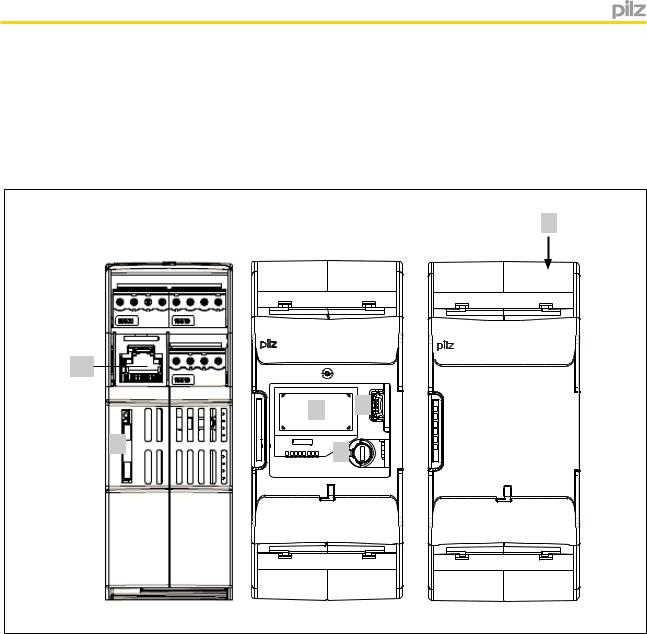
2.2Front/side view
5
|
X3 |
IN1 |
IN2 |
GND Y13 |
Y12 |
Y11 |
Y10 |
Y30 |
||
|
X1 |
|||||||||
|
A1 |
Y1 |
IY2 |
Y35 |
Y34 |
Y33 |
Y32 |
Y31 |
||
|
|
|||||||||
X6 |
PNOZ s30 |
|
|
|
|
|
|
|
||
|
|
|
|
|
|
|
|
|
|
|
|
|
|
|
|
2 |
|
3 |
|
|
|
|
1 |
|
|
|
|
4 |
|
|
|
|
|
|
|
|
|
|
|
|
|
|
|
|
X2 |
A2 |
S11 |
S21 |
S34 13 |
23 |
11 |
21 |
|
|
|
|
|
|
|
14 |
24 |
12 |
22 |
|
|
|
X6 |
|
|
|
|
X4 |
||||
X3 |
IN1 |
IN2 |
|
X1 |
|||
A1 |
Y1 |
||
|
 PNOZ s30
Power
In1
In2
Rel 1
Rel 2
Fault
A2 |
S11 |
X6 X2
GND Y13 Y12 Y11 Y10
IY2 Y35 Y34 Y33 Y32
S21 |
S34 13 |
23 |
11 |
|
14 |
24 |
12 |
Y30
Y31
21 |
|
22 |
X4 |
|
Left: Side view, centre: Front view without cover, right: Front view with cover
Legend:
}A1, A2:
Supply connections
}In1, In2, GND:
Proximity switch 1 - In1 (track A) and 2 - In2 (track B) and GND
}Y10 ... Y13:
Select inputs (SEL1, SEL2, SEL4, SEL8)
}13-14 and 23-24:
Relay outputs (safety contacts)
}11-12 and 21-22:
Relay outputs (auxiliary contacts)
}Y32 ... Y35: Semiconductor outputs (auxiliary outputs)
}S11: +24 V / 30 mA (supply for S34, Y1 and Y2)
}S21: 0 V (GND for S11, S34, Y1 and Y2)
}S34: Reset input
Operating Manual PNOZ s30 |
9 |
1001715-EN-13 |
|

Overview
}Y30: 0 V ext (GND for select input and semiconductor outputs)
}Y31: 24 V ext (supply for semiconductor outputs)
}Y1, Y2:
Y1: Feedback input for Rel. 1 Y2: Feedback input for Rel. 2:
}X6: RJ45 socket for connecting the encoder
(tracks A, /A, B, /B, Z, /Z, S and GND). Proximity switches can be connected via RJ45 socket or connection terminals.
}1: Chip card
}2: Display
}3: USB connection (service only)
}4: Rotary knob
}5: Expansion interface for 2 more external relay outputs
}LEDs:
–Power
–In1
–In2
–Rel 1
–Rel 2
–Fault
Operating Manual PNOZ s30 |
10 |
1001715-EN-13 |
|
Safety
3 Safety
3.1Intended use
The speed monitor monitors standstill, speed, speed range, position and direction in accordance with EN ISO 13849-1 up to PL e and EN IEC 62061 up to SIL CL 3.
WARNING!
Users must take appropriate measures to detect or exclude errors (e.g. slippage or broken shearpin) which cause the frequency of the encoder signal to no longer be proportional to the monitored speed.
Appropriate measures are:
–Using the monitored encoder to also control the drive
–Mechanical solutions
–Z-frequency monitoring with an additional proximity switch (Ini pnp) on the same axis
3.2Safety regulations
3.2.1Use of qualified personnel
The products may only be assembled, installed, programmed, commissioned, operated, maintained and decommissioned by competent persons.
A competent person is someone who, because of their training, experience and current professional activity, has the specialist knowledge required to test, assess and operate the work equipment, devices, systems, plant and machinery in accordance with the general standards and guidelines for safety technology.
It is the company’s responsibility only to employ personnel who:
}Are familiar with the basic regulations concerning health and safety / accident prevention
}Have read and understood the safety guidelines given in this description
}Have a good knowledge of the generic and specialist standards applicable to the specific application.
3.2.2Warranty and liability
All claims to warranty and liability will be rendered invalid if
}The product was used contrary to the purpose for which it is intended
}Damage can be attributed to not having followed the guidelines in the manual
}Operating personnel are not suitably qualified
}Any type of modification has been made (e.g. exchanging components on the PCB boards, soldering work etc.).
Operating Manual PNOZ s30 |
11 |
1001715-EN-13 |
|

Safety
3.2.3Disposal
}In safety-related applications, please comply with the mission time tM in the safety-relat- ed characteristic data.
}When decommissioning, please comply with local regulations regarding the disposal of electronic devices (e.g. Electrical and Electronic Equipment Act).
3.2.4For your safety
}The device is designed exclusively for use in an industrial environment. It is not suitable for use in a domestic environment, as this can lead to interference.
}The guarantee is rendered invalid if the housing is opened or unauthorised modifications are carried out.
}Sufficient fuse protection must be provided on all output contacts with capacitive and inductive loads.
Operating Manual PNOZ s30 |
12 |
1001715-EN-13 |
|

Function description
4 |
Function description |
4.1Introduction
Proximity switches or rotary encoders record measured values, which are evaluated in the speed monitor PNOZ s30. There are 9 monitoring functions (F1 ... F9), which are performed simultaneously.
Up to 16 different parameter sets (P0 ... P15) for the monitoring functions can be selected via the select inputs.
Configuration of the monitoring functions is menu-driven, using a rotary knob. The outputs switch depending on the configuration.
An interface is available to connect a contact expansion module PNOZsigma, enabling the number of outputs to be expanded.
The relay conforms to the following safety criteria:
}The circuit is redundant with built-in self-monitoring.
}The safety function remains effective in the case of a component failure.
4.2Block diagram
A1 |
A2 |
S34 |
S11 |
S21 |
|
In1 In2 GND |
|
13 |
11 |
23 |
21 |
|
~ |
|
Reset/ |
24 V |
0 V |
X6 |
|
|
|
|
|
|
|
|
|
|
|
Initiator |
|
|
|
|
|
|||
|
= |
Start |
|
|
RJ45 |
Relay |
|
|
|
Interface Extended Relais |
||
|
|
|
|
|
Input |
|
Control |
|
|
|
||
|
|
|
|
|
|
|
|
Rel. 1 |
|
|
|
|
Power |
|
|
|
|
|
|
|
|
|
|
||
|
|
|
|
|
|
|
|
Rel. 2 |
|
|
|
|
|
|
Feed- |
|
|
|
|
|
|
|
|
|
|
|
|
|
|
|
|
0 V ext |
24 V ext |
|
|
|
|
|
|
|
back |
|
|
|
Select |
|
|
|
|
||
|
|
|
|
|
|
Inputs (SEL) |
|
|
|
|
||
|
|
Y1 Y2 |
Y32 Y33 Y34 Y35 |
Y10 Y11 Y12 Y13 Y30 Y31 |
14 |
12 |
24 |
22 |
||||
Operating Manual PNOZ s30 |
13 |
1001715-EN-13 |
|

Function description
CAUTION!
The individual blocks are galvanically isolated from each other:
If possible, the connections for the various earth potentials (GND, S21, Y30 und A2) should not be connected on the PNOZ s30 but should be connected directly to the GNDs on the connected units, otherwise noise susceptibility may be increased significantly (conductor loops are not permitted).
–Supply voltage: A1, A2
–Encoder and initiator inputs: GND, In1, In2, RJ45 socket and shield
–Reset and feedback circuits: S21, S11, S34, Y1, Y2
–Semiconductor outputs and select inputs: Y30, Y31, Y32, Y33, Y34, Y35, Y10, Y11, Y12, Y13
–Relay output 13, 14
–Relay output 11, 12
–Relay output 23, 24
–Relay output 21, 22
4.3Functions
The following monitoring functions can be configured:
Standstill
With standstill monitoring, the output is switched on when the value falls below the stated standstill value; if the standstill value is exceeded, the output switches off.
Speed
With speed monitoring, the output switches off when the configured value is exceeded. Timing diagram for standstill/speed monitoring:
v
vmax (F2)
Hys. F2
vmax (F2) - Hys. F2
0
t
F2
t
Operating Manual PNOZ s30 |
14 |
1001715-EN-13 |
|
Function description
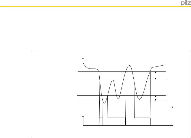
Speed range
With range monitoring, the output switches off if the rotational speed (velocity, frequency) is outside the configured range.
Timing diagram for speed range monitoring:
vmax (F3) |
v |
|
|
|
|
|
|
||
|
|
|
|
|
|
|
Hys. |
F3 |
|
vmax (F3) - Hys. F3 |
|
|
||
|
|
|
|
|
|
|
|
|
|
vmax (F2) + Hys. F2 |
|
|
Hys. |
F2 |
vmax (F2) |
|
|
||
0 |
|
|
t |
|
|
|
|||
|
|
|
||
|
|
|
|
F2-F3
t
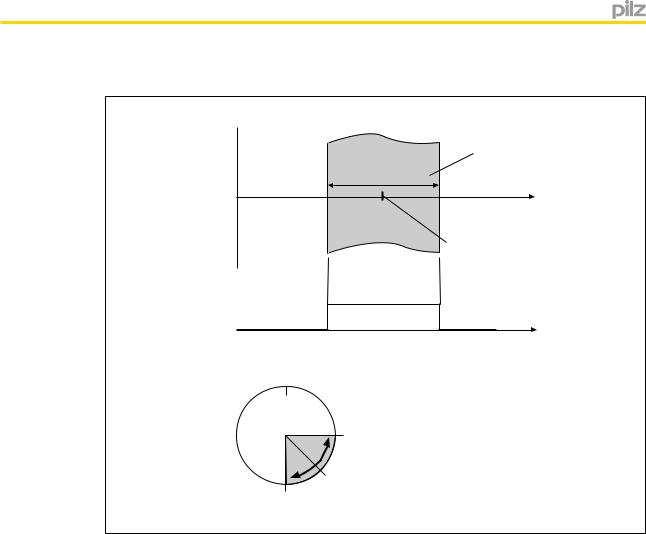
Position
Position monitoring is activated via a rising edge at the start input. The current position is adopted as a reference position in the middle of the position window (configured window width) and the assigned output is switched on.
The output will stay switched on provided the current position is within the position window.
Operating Manual PNOZ s30 |
15 |
1001715-EN-13 |
|
Function description
Timing diagram for position monitoring:
v
Position window
Configured window width
s
Reference position (rising edge at S34)
F2 
A |
B |
s |
|
|
0°
Position
B
Reference position
A(rising edge at S34)
If the position moves outside the configured range, position monitoring is reset and the assigned outputs are switched off. Position monitoring can be restarted via a rising edge at the start input
A max. of 4 positions can be configured to be monitored simultaneously. Please note:
}Active position monitoring is not restarted by another rising edge at the start input.
}Active position monitoring continues unchanged even if a different parameter set is selected, which also uses position monitoring. This also applies if position monitoring is used in a different switch function.
}Active position monitoring is reset if another parameter set is selected, which does not use position monitoring.
}Position monitoring cannot be used if proximity switches are employed.
Direction
If the direction is to be detected safely, this function must be linked to a safety contact.
}If "Direct. Right" is configured, the safety output is switched on during normal operation in clockwise rotation.
}If "Direct. Left" is configured, the safety output is switched on during normal operation in anti-clockwise rotation.
For both directions, a tolerance can be entered for the wrong direction. In other words, the drive can run in the wrong direction up to the set tolerance value, without the assigned output switching off.
Operating Manual PNOZ s30 |
16 |
1001715-EN-13 |
|
Function description
If an output has been switched off, it cannot switch back on again until the drive has been run in the right direction up to the tolerance value.
Please note:
}Direction monitoring is always active, irrespective of whether it is used in the selected parameter set.
}Direct.Right and Direct.Left are active when the PNOZ s30 is started up.
}Direction cannot be detected if proximity switches are used.
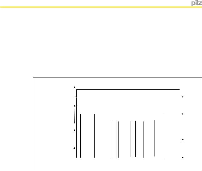
Timing diagram for direction monitoring:
UB
Direction |
|
|
|
|
|
|
|
|
|
|
|
|
|
|
|
|
|
|
s |
|
Right |
|
|
|
|
|
|
|
|
|
|
|
|
|
|
|
|
|
|
|
|
|
|
|
|
|
|
|
|
|
|
|
|
|
|
|
|
|
|
|
||
Standstill |
|
|
|
|
|
|
|
|
|
|
|
|
|
|
|
|
|
|
s |
|
|
|
|
|
|
|
|
|
|
|
|
|
|
|
|
|
|
|
|||
Left |
|
|
|
|
|
|
|
|
|
|
|
|
|
|
|
|
|
|
||
|
|
|
|
|
|
|
|
|
|
|
|
|
|
|
|
|
|
|
||
Direct.Right |
|
|
|
|
|
|
|
|
|
|
|
|
|
|
|
|
|
|
|
|
|
|
|
|
|
|
|
|
|
|
|
|
|
|
|
|
|
|
|
||
|
|
|
|
|
|
|
|
|
|
|
|
|
|
|
|
|
|
|
||
|
|
|
|
|
|
|
|
|
|
|
|
|
|
|
|
|
|
|
|
|
Wrong |
0000... |
|
12344... |
3212100... |
|
1233... |
44... |
44... |
32100... |
|
s |
|||||||||
direction: |
|
|
|
|
|
|
|
|
|
|
|
|
|
|
|
|
|
|
|
|
|
|
|
|
|
|
|
|
|
|
|
|
|
|
|
|
|
|
|
|
|
Direct.Left |
|
|
|
|
|
|
|
|
|
|
|
|
|
|
|
|
|
|
|
|
|
|
|
|
|
|
|
|
|
|
|
|
|
|
|
|
|
|
|
|
|
Wrong |
|
|
|
|
|
|
|
|
|
|
|
|
|
|
|
|
||||
|
00012344... |
|
32100... |
1232344... |
|
32111... |
0 |
0... |
00... |
12344... |
|
s |
||||||||
direction: |
|
|
|
|
|
|
|
|
|
|
|
|
|
|
|
|
|
|
|
|
Configuration in the example:
}Wrong direction in anti-clockwise rotation Max. right: 3 pulses
}Wrong direction in clockwise rotation Max. left: 3 pulses
Monitoring for broken shearpins
An additional proximity switch or an HTL signal from an additional rotary encoder can be connected to track Z to monitor for broken shearpins. These must both be configured as Z-frequency monitoring.
Hysteresis
For each switch function F1 ... F9 (with the exception of direction and position), a hysteresis can be configured. This prevents the outputs on the speed monitor from bouncing if there are fluctuations around the response value. The hysteresis becomes effective when the output is switched on:
Switch-on value = switching threshold – hysteresis For the lower range limit:
Switch-on value = switching threshold + hysteresis
Operating Manual PNOZ s30 |
17 |
1001715-EN-13 |
|

Function description
Start modes
You can choose between the following start modes:
}Automatic start
If an automatic start is configured, the output switches on automatically if the speed does not reach the limit value, for example.
}Monitored start with rising edge
If a monitored start with rising edge is configured, the output switches on if the speed does not reach the limit value and then a rising edge is detected at S34.
}Monitored start with falling edge
If a monitored start with falling edge is configured, the output switches on if the speed does not reach the limit value and then a falling edge is detected at S34.
Switch delay
A delay time can be set for each output (see technical details). The outputs will not switch until the set time has elapsed. It is possible to configure whether the delay time is to be activated when switching on, switching off, or switching on and off.
WARNING!
Potential loss of safety function due to increased reaction time
The output switch-off delay (tdo, Off) when overspeed is reached will increase the speed monitor's reaction time by the stated value (see technical details). This must not delay the arrival of a safe condition by more than the permitted time. The configuration of the switch-off delay must be considered in the risk assessment as regards hazards, reaction time and safety distance.
Feedback loops
Feedback loops are used to monitor external contactors or relays. The corresponding feedback loop must be closed before starting.
Start-up delay
A start-up delay time can be configured, which prevents the evaluation of the encoder signals for the configured time period after the supply voltage is switched on.
Switching direction on semiconductor outputs
The semiconductor outputs can be operated in normally de-energised or normally energised mode.
Units
The values to be configured can be entered in various units. Depending on the axis type (linear or rotational axis), various units can be selected for speed and distance (see chapter entitled "Menu overview").
Operating Manual PNOZ s30 |
18 |
1001715-EN-13 |
|

Function description
4.3.1Timing diagram for speed monitoring
v |
|
|
|
|
|
|
|
|
|
|
|
|
|
vmax (F2) |
|
|
|
|
|
|
|
|
|
|
Hys. F2 |
||
|
|
|
|
|
||
vmax (F2) - Hys. F2 |
|
|
|
|
|
|
|
|
|
|
|
|
|
0 |
|
|
|
|
|
|
F2 |
|
|
|
|
t |
|
|
|
|
|
|
|
|
|
|
|
|
|
|
|
Example: Rel. 1 |
|
|
|
|
t |
|
|
|
|
|
|
|
|
Delay time (tv) |
|
|
|
|
|
|
Rel. 1 |
On |
Off |
On |
Off |
|
|
Delay effect: |
|
|
||||
On Off |
Switch-on |
Too short |
|
Switch-off |
t |
|
|
delay |
|
|
delay |
|
|
Delayed (+filtered)
|
|
t |
|
Reset mode monitored/ |
|
|
|
Start |
Too short |
Too short |
|
pulse duration |
|||
|
|
Feedback loop
t
Rel. 1
t
Configuration in the example:
}Switch function: F2
}Assigned output: Rel. 1
}Delay effect on outputs: On + Off
}Reset mode: Monitored /
4.4Speed configuration
The speed monitor is configured using the rotary knob on the device.
Up to 16 parameter sets (P0 ... P15), each with a max. of 9 switch functions (F1 ... F9) can be configured to monitor various operating modes, for example.
One of the 16 parameter sets is selected via 4 select inputs SEL1 (Y10), SEL2 (Y11), SEL4 (Y12), SEL8 (Y13).
Operating Manual PNOZ s30 |
19 |
1001715-EN-13 |
|

Function description
The switch functions are monitored simultaneously.
Each of a switch function's 16 parameters can be configured as
}Standstill limit
}Speed limit
}Upper or lower limit of speed range
}Right-hand direction monitoring
}Left-hand direction monitoring
}Position monitoring 1 to 4 with width of position window 1 to 4
Exactly one switch function can be assigned to each output. The same switch function can be assigned to several outputs. With range monitoring, a range is assigned to an output (F2-F3, F4-F5, F6-F7 or F8-F9).
A switch delay and start mode can be configured for each output.
If only one parameter set is used, configure the mode "Select inputs: None". The select inputs will then be ignored.
Information
2 basic configurations are available for standard applications, for simple configuration within the display menu. A basic configuration contains limited menu functions adapted for standard applications, with partly pre-defined parameters. Further information about basic configurations can be found in this chapter, under "Basic configuration".
Example configuration:
2 parameter sets for 2 operating modes are configured:
}Set-up: P1
}Automatic mode: P2
The parameter set P1 is used to monitor a reduced speed.
The parameter set P2, "Automatic mode", is selected for speed monitoring (selection via the select inputs, see next chapter "Select inputs").
The following switch functions are configured for the parameter set P1:
}F1: Standstill 2 Hz
}F2: Overspeed: 50 Hz
}F3: Warning threshold: 50 Hz
The following switch functions are configured for the parameter set P2:
}F1: Standstill 2 Hz
}F2: Overspeed: 3000 Hz
}F3: Warning threshold: 2800 Hz
The following outputs are assigned to the switch functions:
}F1: Relay output Rel. 1
}F2: Relay output Rel. 2
}F3: Semiconductor output Out 1
Operating Manual PNOZ s30 |
20 |
1001715-EN-13 |
|

Function description
For documentation and a better overview of the device settings, we recommend that you fill in this configuration overview before setting the device parameters (link to form, see "Create configuration overview" chapter).
4.4.1Select Inputs
The parameter sets are selected via the 4 select inputs SEL1 (Y10), SEL2 (Y11), SEL4 (Y12), SEL8 (Y13). Only one of the configured parameter sets can be selected.
One of the following modes can be selected in the "Select inputs mode" menu, depending on the application:
"None" mode
For applications up to PL e of EN ISO 13849-1 and SIL CL 3 of EN IEC 62061.
The select inputs are ignored. Only the parameter set P0 is configured and used. The lowest frequency (10 mHz) is automatically set for all other parameter sets.
"1 from 4" mode
For applications up to PL e of EN ISO 13849-1 and SIL CL 3 of EN IEC 62061. A maximum of 4 parameter sets can be configured and used: P1, P2, P4 and P8.
Operating Manual PNOZ s30 |
21 |
1001715-EN-13 |
|

Function description
Parameter set |
Signal states of the select inputs |
|
||
|
SEL 8 (Y13) |
SEL 4 (Y12) |
SEL 2 (Y11) |
SEL 1 (Y10) |
|
|
|
|
|
P1 |
0 |
0 |
0 |
1 |
|
|
|
|
|
P2 |
0 |
0 |
1 |
0 |
|
|
|
|
|
P4 |
0 |
1 |
0 |
0 |
|
|
|
|
|
P8 |
1 |
0 |
0 |
0 |
|
|
|
|
|
When using these 4 parameter sets, the following safety features are met:
If there is an error when activating the select inputs, such as
}Short circuits and shorts between contacts
}Open circuit
}Input drift
a parameter set other than P1, P2, P4 or P8 is selected.
The lowest frequency (10 mHz) is automatically set for the other parameter sets (P0, P3, P5 ... P7, P9 ... P15). If one of these parameter sets is selected, an error message appears and all outputs switch off.
"All 16" mode
In this mode, the number of parameter sets can be increased to max. 16. This mode can only be used for applications up to max. PL d of EN ISO 13849-1 and up to SIL CL 2 of EN IEC 62061.
Parameter set |
Signal states of the select inputs |
|
||
|
SEL 8 (Y13) |
SEL 4 (Y12) |
SEL 2 (Y11) |
SEL 1 (Y10) |
|
|
|
|
|
P0 |
0 |
0 |
0 |
0 |
|
|
|
|
|
P1 |
0 |
0 |
0 |
1 |
|
|
|
|
|
P2 |
0 |
0 |
1 |
0 |
|
|
|
|
|
P3 |
0 |
0 |
1 |
1 |
|
|
|
|
|
P4 |
0 |
1 |
0 |
0 |
|
|
|
|
|
P5 |
0 |
1 |
0 |
1 |
|
|
|
|
|
P6 |
0 |
1 |
1 |
0 |
|
|
|
|
|
P7 |
0 |
1 |
1 |
1 |
|
|
|
|
|
P8 |
1 |
0 |
0 |
0 |
|
|
|
|
|
P9 |
1 |
0 |
0 |
1 |
|
|
|
|
|
P10 |
1 |
0 |
1 |
0 |
|
|
|
|
|
P11 |
1 |
0 |
1 |
1 |
|
|
|
|
|
P12 |
1 |
1 |
0 |
0 |
|
|
|
|
|
P13 |
1 |
1 |
0 |
1 |
|
|
|
|
|
P14 |
1 |
1 |
1 |
0 |
|
|
|
|
|
P15 |
1 |
1 |
1 |
1 |
|
|
|
|
|
Operating Manual PNOZ s30 |
22 |
1001715-EN-13 |
|

Function description
When using the expanded parameter sets, please note:
If an open circuit occurs when the select inputs are activated, the system will switch to a parameter set with a lower number (e.g. P7 -> P3 if an open circuit occurs at SEL4).
The limit values for the switch functions should therefore be entered in ascending order. (Parameter set P0 -> lowest values, parameter set P15 -> highest values).
Delay on the select inputs
A reaction time can be entered for the select inputs. That way it is possible to filter out invalid signals (e.g. contact bounce or an intermediate state) that occur when switching.
4.4.2Switch functions
The following switch functions can be configured:
}Standstill
The standstill frequency is configured centrally. The standstill frequency should be the lowest frequency in the configuration.
All switch function parameters are pre-configured to the lowest frequency ex works.
}Speed
Limit values can be configured to monitor for overspeed.
Limit values should be entered in ascending order (Parameter set P0 -> lowest values, parameter set P15 -> highest values)
}Speed range
Up to 4 speed ranges can be monitored simultaneously. Configure two switch functions to monitor a range:
–F2 and F3,
–F4 and F5,
–F6 and F7 or
–F8 and F9.
The switch function with the lower number (e.g. F2) operates as the lower range limit; the switch function with the higher number (e.g. F3) operates as the upper range limit.
Both switch functions can be assigned to one or more outputs.
}Position
Up to 4 different position windows can be monitored: Position 1 ... Position 4.
Each position to be monitored can be entered as often as necessary in parameter sets P0 to P15 and switch functions F1 to F9.
}Direction
The monitoring functions "Direct. Left" and "Direct. Right" can be configured as a switch function as often as necessary.
For both directions, a tolerance can be entered for the wrong direction.
4.4.3Basic configuration
Two basic configurations are available for standard applications, for simple configuration within the display menu. A basic configuration contains limited menu functions adapted for standard applications, with partly pre-defined parameters.
Operating Manual PNOZ s30 |
23 |
1001715-EN-13 |
|

Function description
The following basic configurations are available: Basic configuration 1: Ini pnp pnp (proximity switch) Pre-defined settings and configuration options:
}Encoder type
2 pnp type proximity switches
}Switch functions
–Standstill (F1)
–Standstill frequency configurable in Hz
–Speed (F2)
–Max. frequency (v max) configurable in Hz
}Parameter set/select input
P0, select inputs are ignored ("None" mode")
}Hysteresis
Standstill and speed, 2 % each
}Output assignment
–Standstill: Relay output Rel. 1 and semiconductor output Out 1
–Speed: Relay output Rel. 2 and semiconductor output Out 2
}Reset mode
–Rel. 1, Rel. 2 Out 1, Out 2: Automatic reset
}Switch delay
None
}Max. encoder frequency
3.5 kHz
Basic configuration 2: Rotary encoder
}Encoder type
Rotary encoders
–Rotary encoder type configurable
}Switch functions
–Standstill (F1)
–Standstill frequency configurable in Hz
–Speed (F2)
–Max. frequency (v max) configurable in Hz
–Direction (F3)
Direction left
Tolerance for wrong direction = 10 Imp
–Direction (F4)
Direction right
Tolerance for wrong direction = 10 Imp
Operating Manual PNOZ s30 |
24 |
1001715-EN-13 |
|

Function description
}Parameter set/select input
P0, select inputs are ignored ("None" mode")
}Hysteresis
Standstill and speed, 2 % each
}Output assignment
–Standstill: Relay output Rel. 1 and semiconductor output Out 1
–Speed: Relay output Rel. 2 and semiconductor output Out 2
–Direction left: External output Ext. 1 and semiconductor output Out 3
–Direction right: External output Ext. 2 and semiconductor output Out 4
}Reset mode
–All outputs: Automatic reset
}Switch delay
None
}Max. encoder frequency
1 MHz
For details of how to configure the basic configurations, see the chapter entitled Commissioning/Display Menu - Configuration.
4.4.4Chip card
The set parameters, the name of the configuration, the check sum and the passwords are stored on the chip card (see section entitled "Using the chip card").
4.5Input device types
4.5.1Proximity switch
}The following proximity switches can be used:
–pnp
–npn
}The proximity switches must be fitted so that at least one is always activated. In other words, the proximity switches must be fitted so that the recorded signals always overlap.
}The cable used to connect the proximity switches must be shielded (see connection diagrams in the chapter entitled "EMC-compliant wiring").
}The supply voltage of the proximity switches should be monitored via track S.
Operating Manual PNOZ s30 |
25 |
1001715-EN-13 |
|

Function description
Proximity switch assembly:
|
|
|
|
Ini 1 |
|
|
Ini 2 |
|
|
|
|
|
|
|||||
|
|
|
|
|
|
|
|
|
|
|
|
|
|
|
|
|
|
|
|
|
|
|
|
|
|
|
|
|
|
|
|
|
|
|
|
|
|
|
|
|
|
|
|
|
|
|
|
|
|
|
|
|
|
|
|
|
|
|
|
|
|
|
|
|
|
|
|
|
|
|
|
|
|
|
|
|
|
|
|
|
|
|
|
|
|
|
|
|
|
|
|
|
|
|
Example pnp – pnp:
Proximity switch 1
Proximity switch 2
Energised
De-energised
Energised
De-energised
> 1 % of the period length
ATTENTION!
Appropriate installation measures should be taken to prevent a foreign body coming between the signal encoder and the proximity switch. If not, the foreign body could cause invalid signals.
}Please note the values stated in the technical details
}The maximum frequency of the used encoders must be entered for a complete configuration ("Encoder" Menu -> "Track AB" -> "Track AB fmax" / "Track Z" -> "Track Z fmax").
4.5.2Rotary encoders
}The following rotary encoders can be used:
–TTL, HTL (single-ended or differential signals)
–sin/cos 1 Vss
–Hiperface
}The rotary encoders can be connected with or without Z index (0 index)
}The cable used to connect the rotary encoders must be shielded (see connection diagrams in the chapter entitled "EMC-compliant wiring").
}A proximity switch can also be connected to track Z for monitoring broken shearpins
}Track S can be used:
–To connect an encoder's error output
–To monitor voltages between 0 V and 30 V for a permitted upper and lower limit. For example, the encoder's supply voltage can be monitored.
Operating Manual PNOZ s30 |
26 |
1001715-EN-13 |
|
Function description
}The following must be entered for a complete configuration:
–The maximum frequency of the used encoders ("Encoder Settings" menu -> "Track AB" -> "Track AB fmax" / "Track Z" -> "Track Z fmax").
–The ratio fAB/fZ ("Encoder Settings" menu -> "Track Z" -> fAB/fZ Verh.)
Please note the values stated in the technical details
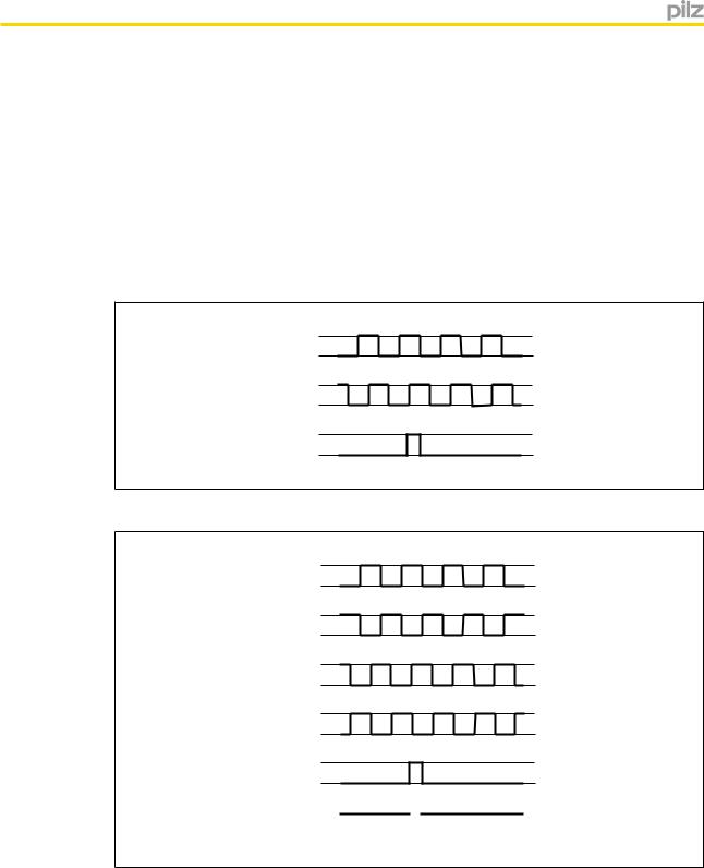
4.5.2.1Output signals
Output signals TTL, HTL
} Single ended
AU 0
BU 0
(Z)U
0
}Differential
AU 0
/A U 0
BU
0
/B U 0
(Z)U
0
(/Z) U0 
Operating Manual PNOZ s30 |
27 |
1001715-EN-13 |
|
Loading...