


21904-3FR-03 PSEN sl-0.5p
4 D Betriebsanleitung
4 GB Operating instructions
4 F Manuel d'utilisation
Sicheres Schutztürsystem PSENslock PSENslock safety gate system
Das sichere Schutztürsystem erfüllt die Anforderungen nach
`EN 60204-1
`EN 60947-5-3: PDF-M zusammen mit dem Betätiger (siehe Technische Daten).
`EN 62061: SIL CL 3
`EN ISO 13849-1. PL e und Kat. 4
`Der Sicherheitsschalter darf nur mit dem zugehörigen Betätiger verwendet werden (siehe Technische Daten).
Die Sicherheitsausgänge müssen 2-kanalig weiterverarbeitet werden.
The safety gate system meets the requirements in accordance with
`EN 60204-1
`EN 60947-5-3: PDF-M in conjunction with the actuator (see Technical Details).
`EN 62061: SIL CL 3
`EN ISO 13849-1. PL e and Cat. 4
`The safety switch may only be used with the corresponding actuator (see Technical Details).
The safety outputs must use 2-channel processing.
Zu Ihrer Sicherheit |
For your safety |
` Installieren und nehmen Sie das Gerät nur |
` Only install and commission the unit if you |
dann in Betrieb, wenn Sie diese Betriebsan- |
have read and understood these operating |
leitung gelesen und verstanden haben und |
instructions and are familiar with the applica- |
Sie mit den geltenden Vorschriften über Ar- |
ble regulations for health and safety at work |
beitssicherheit und Unfallverhütung vertraut |
and accident prevention. |
sind. |
Ensure VDE and local regulations are met, |
Beachten Sie die VDEsowie die örtlichen |
especially those relating to safety. |
Vorschriften, insbesondere hinsichtlich |
` Any guarantee is rendered invalid if the hous- |
Schutzmaßnahmen |
ing is opened or unauthorised modifications |
` Durch Öffnen des Gehäuses oder eigen- |
are carried out. |
mächtige Umbauten erlischt jegliche Ge- |
` Do not remove the protective cap until you |
währleistung. |
are just about to connect the unit. |
` Entfernen Sie die Schutzkappe erst unmittel- ` Notice! |
|
bar vor Anschluss des Geräts. |
The magnet surface and counterplate may |
` Wichtig! |
heat up. When installing, make sure that |
Die Magnetoberfläche und die Gegenplatte |
heat dissipation is guaranteed. |
können sich erwärmen. Achten Sie bei der |
|
Montage darauf, dass die Wärmeabfuhr ge- |
|
währleistet ist. |
|
Système de sécurité pour protecteurs mobiles PSENslock
Le système de sécurité pour protecteurs mobiles satisfait aux exigences des normes
`EN 60204-1
`EN 60947-5-3 : PDF-M avec l'actionneur (voir les caractéristiques techniques).
`EN 62061 : SIL CL 3
`EN ISO 13849-1. PL e et cat. 4
`Le capteur de sécurité doit être utilisé uniquement avec l'actionneur correspondant
(voir les caractéristiques techniques).
Les sorties de sécurité doivent être traitées par 2 canaux.
Pour votre sécurité
`Vous n'installerez l'appareil et ne le mettrez en service qu'après avoir lu et compris le présent manuel d'utilisation et vous être familiarisé avec les prescriptions en vigueur sur la sécurité du travail et la prévention des accidents.
Respectez les normes locales ou VDE, particulièrement en ce qui concerne la sécurité.
`L'ouverture de l'appareil ou sa modification annule automatiquement la garantie.
`Veuillez retirer le cache de protection avant de raccorder l'appareil.
`Important !
La surface magnétique et la contreplaque peuvent chauffer. Pour le montage, faites attention à ce que l'évacuation de la chaleur soit assurée.
Gerätemerkmale |
Unit features |
Caractéristiques de l'appareil |
|||
` Transpondertechnik |
` Transponder technology |
` Technique à transpondeur |
|||
` Gerätevarianten: |
` Unit types: |
` Modèles d'appareils : |
|||
– |
PSEN sl-0.5p 1.1: codiert |
– |
PSEN sl-0.5p 1.1: Coded |
– |
PSEN sl-0.5p 1.1 : codé |
– |
PSEN sl-0.5p 2.1: vollcodiert |
– |
PSEN sl-0.5p 2.1: Fully coded |
– |
PSEN sl-0.5p 2.1 : codé multiple |
– |
PSEN sl-0.5p 2.2: unikat codiert |
– |
PSEN sl-0.5p 2.2: Uniquely coded |
– |
PSEN sl-0.5p 2.2 : codé unique |
` Zweikanaliger Betrieb |
` Dual-channel operation |
` Commande par 2 canaux |
|||
` 2 Sicherheitsausgänge |
` 2 safety outputs |
` 2 sorties de sécurité |
|||
` 2 Eingänge für Reihenschaltung |
` 2 inputs for series connection |
` 2 entrées pour montage en série |
|||
` 1 Meldeausgang |
` 1 signal output |
` 1 sortie de signalisation |
|||
` Magnetische Zuhaltung für Prozessschutz |
` Magnetic guard locking for process protec- |
` Interverrouillage magnétique pour protéger |
|||
` 1 Eingang zum Ein-/Ausschalten des Zuhal- |
tion |
les process |
|||
temagnets |
` 1 input to switch the locking magnet on/off |
` 1 entrée pour l'activation / la désactivation |
|||
` LED-Anzeige für |
` LEDs for |
de l'aimant d'interverrouillage |
|||
– |
Versorgungsspannung/Fehler |
– |
Supply voltage/fault |
` LED de visualisation pour |
|
– |
Tür geschlossen |
– |
Gate closed |
– |
tension d'alimentation / défauts |
– |
Zustand Eingänge |
– |
Status of the inputs |
– |
protecteur mobile fermé |
– |
Zustand magnetische Zuhaltung |
– |
Status of the magnetic guard locking de- |
– |
état des entrées |
` 8-poliger M12-Anschlussstecker |
|
vice |
– |
état de l'interverrouillage magnétique |
|
|
|
` 8-pin M12 connector |
` connecteur M12 à 8 broches |
||
- 1 -
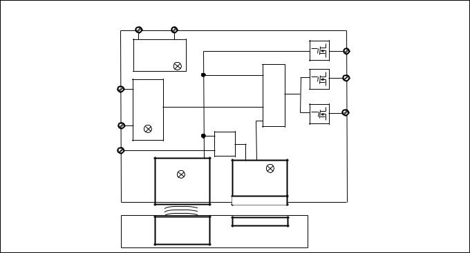
Blockschaltbild Block diagram Schéma de principe
UB |
A2 |
|
A1 |
|
|
Netzteil |
Y32 |
|
Power supply |
||
Alimentation |
|
|
Power / Fault |
|
|
|
|
12 |
S11 |
|
& |
& |
|
|
|
22 |
|
Input |
|
|
|
|
|
S21 |
|
|
S31 |
|
& |
|
|
|
|
Safety Gate |
Lock |
|
|
|
|
Empfänger |
Magnet |
|
Magnet |
|
|
Receiver |
Aimant |
|
Récepteur |
|
Betätiger
Actuator
Actionneur
Funktionsbeschreibung |
Function description |
Description du fonctionnement |
An den Sicherheitsausgängen 12 und 22 liegt ein High-Signal, wenn gleichzeitig:
`der Betätiger im Ansprechbereich ist. (Schutztür geschlossen) und
`die Eingänge S11 und S21 high sind und
`der Eingang S31 high ist (Steuerbefehl für magnetische Zuhaltung) und der Zuhaltema-
gnet eingeschaltet ist.
Der Meldeausgang Y32 ist high, wenn: ` Der Betätiger im Ansprechbereich ist
Die Sicherheitsausgänge 12 und 22 sind low, wenn:
`Der Betätiger sich außerhalb des Ansprechbereichs befindet oder
`die Eingänge S11 und S21 low sind oder
`der Eingang S31 low ist (Steuerbefehl für magnetische Zuhaltung) und der Zuhaltemagnet ausgeschaltet ist
Wurden die Sicherheitsausgänge durch einen der Eingänge S11 oder S21 abgeschaltet, dann ist ein Wiedereinschalten nur möglich, nachdem beide Eingänge gleichzeitig low waren. Die Sicherheitseingänge S11 und S21 werden auf Plausibilität überwacht. Beide Eingänge müssen gemeinsam ausund einschalten (Teilbetätigungssperre).
Magnetische Zuhaltung und Magnetüberwachung
`Der Zuhaltemagnet wird eingeschaltet, wenn S31 high ist und der Betätiger erkannt wird (Schutztür geschlossen).
`Die Haltekraft des Zuhaltemagneten wird beim Einschalten getestet. Die Sicherheitsausgänge wechseln in den High-Zustand,
nachdem die Mindestzuhaltekraft erreicht wurde.
Wird am eingeschalteteten Zuhaltemagneten Windungsunterbruch, oder Windungskurzschluss erkannt, wechseln die Sicherheitsausgänge 12 und 22 in den Low-Zustand.
 INFO
INFO
Wenn die Schutztür im zugehaltenen Zustand gewaltsam geöffnet wird, schalten die Sicherheitsausgänge ab.
There is a high signal at safety output 12 and 22 if the following occur simultaneously:
`The actuator is within the response range (safety gate closed) and
`Inputs S11 and S21 are high and
`Input S31 is high (control command for magnetic guard locking) and the locking magnet
is switched on.
Signal output Y32 is high if:
`The actuator is within the response range Safety outputs 12 and 22 are low if:
`The actuator is outside the response range or
`Inputs S11 and S21 are low or
`Input S31 is low (control command for magnetic guard locking) and the locking magnet
is switched off.
If the safety outputs have been shut down by either of the inputs S11 or S21, they cannot be switched back on until both inputs are low simultaneously.
Safety inputs S11 and S21 are monitored for feasibility. Both inputs must switch off and on together (partial operation lock).
Magnetic guard locking device and magnet monitoring
`The locking magnet is switched on if S31 is high and the actuator is detected (safety gate closed).
`The holding force of the locking magnet is tested on power-up. The safety outputs switch to a high state once the minimum
holding force is achieved.
If an open winding or a winding short circuit is detected on a locking magnet that is switched on, safety outputs 12 and 22 switch to a low state.
 INFORMATION
If the safety gate is in a locked condition and is opened by force, the safety outputs will shut down.
Un niveau haut est généré sur les sorties de sécurité 12 et 22, si en même temps :
`l'actionneur est dans la zone de déclenchement (protecteur mobile fermé) et
`les entrées S11 et S21 sont activées et
`l'entrée S31 est activée (ordre de commande pour interverrouillage magnétique) et
l'aimant d'interverrouillage est activé.
La sortie de signalisation Y32 est à l'état "1" si : ` l'actionneur est dans la zone de déclenche-
ment
Les sorties de sécurité 12 et 22 ne sont pas activées si :
`l'actionneur se situe en dehors de la zone de déclenchement ou
`les entrées S11 et S21 sont à l'état "0" ou
`l'entrée S31 est à l'état "0" (ordre de commande pour interverrouillage magnétique) et
l'aimant d'interverrouillage est désactivé. Si les sorties de sécurité ont été désactivées par l'une des entrées S11 ou S12, leur réen-
clenchement n'est possible qu'une fois que les entrées soient passées en même temps à l'état "0".
La plausibilité des entrées de sécurité S11 et S12 est surveillée. Les deux entrées doivent être mises hors tension et sous-tension ensemble (blocage de commande partielle).
Interverrouillage magnétique et surveillance magnétique
`L'aimant magnétique est activé si S31 est à l'état "1" et si l'actionneur est détecté (protecteur mobile fermé).
`La force d'interverrouillage de l'aimant magnétique est testée lors de l'activation. Les sorties de sécurité sont activées une fois que
la force minimale d'interverrouillage est atteinte.
Si une coupure de la bobine ou un court-circuit de la bobine est détecté sur l'aimant magnétique activé, les sorties de sécurité 12 et 22 passent à l'état "0".
 INFORMATION
Si le protecteur mobile en position fermée est ouvert par la force, les sorties de sécurité sont désactivées.
- 2 -
Seitenund Höhenversatz |
Lateral and vertical offset |
Décalage latéral et en hauteur |
|
Höhenversatz/Vertical offset/Décalage vertical |
Seitenversatz/Lateral offset/ |
|
|
Décalage latéral |
|
<![if ! IE]> <![endif]>Fault / Power Gate Safety Input Lock |
|
Verdrahtung |
Wiring |
Raccordement |
Beachten Sie:
`Angaben im Abschnitt „Technische Daten“ unbedingt einhalten.
`Berechnung der max. Leitungslänge Imax im Eingangskreis:
Imax = Rlmax
Rl / km
Rlmax = max. Gesamtleitungswiderstand (s. techn. Daten)
Rl / km = Leitungswiderstand/km
Please note:
`Information given in the “Technical details” must be followed.
`Calculation of the max. cable length lmax in the input circuit:
Imax = Rlmax
Rl / km
Rlmax = max. overall cable resistance (see Technical details)
Rl / km = cable resistance/km
Important :
`Respectez impérativement les données indiquées dans la partie "Caractéristiques techniques".
`Calcul de la longueur de câble max. Imax sur le circuit d'entrée :
Imax = Rlmax
Rl / km
Rlmax = résistance max. de l'ensemble du câblage (voir les caractéristiques techniques)
Rl / km = résistance du câblage/km
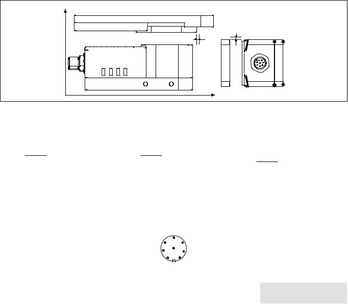
Anschlüsse |
Connections |
|
Raccordements |
|
Stiftstecker 8-pol. M12 |
Connector 8 pin M12 |
Connecteur mâle M12 à 8 broches |
||
|
|
|
|
|
|
|
5 |
|
|
|
6 |
4 |
|
|
|
7 |
8 |
|
|
|
3 |
|
|
|
|
1 |
2 |
|
|
|
|
|
|
|
Anschlussbelegung |
Pin assignment |
|
Affectation des bornes |
|
|
|
|
|
|
PIN/ |
Funktion/ |
Klemmenbezeichnung/ |
|
Adernfarbe (Pilz Kabel)/ |
Broche |
Function/ |
Terminal designation/ |
|
Cable colour (Cable Pilz)/ |
|
Foncion |
Désignation des bornes |
|
Couleur du fil (fil de Pilz) |
1 |
Eingang Kanal 2/ |
S21 |
|
weiß/white/blanc |
|
Input, channel 2/ |
|
|
|
|
Canal d'entrée 2 |
|
|
|
|
|
|
|
|
2 |
+24 UB |
A1 |
|
braun/brown/marron |
|
|
|
|
|
3 |
Ausgang Kanal 1/ |
12 |
|
grün/green/vert |
|
Output, channel 1/ |
|
|
|
|
Canal de sortie 1 |
|
|
|
|
|
|
|
|
4 |
Ausgang Kanal 2/ |
22 |
|
gelb/yellow/jaune |
|
Output, channel 2/ |
|
|
|
|
Canal de sortie 2 |
|
|
|
|
|
|
|
|
5 |
Meldeausgang "Lock"/ |
Y32 |
|
grau/grey/gris |
|
Signal output "Lock"/ |
|
|
|
|
Sortie message "Lock" |
|
|
|
|
|
|
|
|
6 |
Eingang Kanal 1/ |
S11 |
|
rosa/pink/rose |
|
Input, channel 1/ |
|
|
|
|
Canal d'entrée 1 |
|
|
|
|
|
|
|
|
7 |
0 V UB |
A2 |
|
blau/blue/bleu |
|
|
|
|
|
8 |
"Lock_Unlock" |
S31 |
|
rot/red/rouge |
|
|
|
|
|
- 3 -
Anschluss an Auswertegeräte
Bitte beachten Sie:
`das Netzteil muss den Vorschriften für Kleinspannungen mit sicherer Trennung (SELV, PELV) entsprechen.
`die Einund Ausgänge des Sicherheitsschalters müssen eine sichere Trennung zu Spannungen über 60 V AC besitzen.
 ACHTUNG!
Die Sicherheitsausgänge müssen 2-ka- nalig weiterverarbeitet werden.
 INFO
INFO
Sicherheitsschaltgeräte mit Weitspannungsnetzteil oder in der Geräte-Variante (AC) haben eine interne Potentialtrennung und sind als Auswertegeräte nicht geeignet.
Connection to evaluation devices
Please note:
`The power supply must meet the regulations for extra low voltages with safe separation (SELV, PELV).
`the inputs and outputs of the safety switch must have a safe separation to voltages over 60 V AC.
 CAUTION!
The safety outputs must use 2-channel processing.
 INFORMATION
AC versions of safety relays or safety relays with a universal power supply have internal potential isolation and are unsuitable as evaluation devices.
Raccordement aux appareils de contrôle
Tenez compte de ce qui suit :
`Cette alimentation doit être conforme aux prescriptions relatives aux basses tensions à séparation galvanique (SELV, PELV).
`Les entrées et les sorties du capteur de sécurité doivent posséder une séparation galvanique pour les tensions supérieures à
60 V AC.
 ATTENTION !
Les sorties de sécurité doivent être traitées par 2 canaux.
 INFORMATION
Les capteurs de sécurité avec alimentation universelle ou dans le modèle appareil (AC) disposent d'une séparation de potentiel interne et ne sont pas adaptés comme appareils de contrôle.
` Einzelschaltung |
` Single connection |
` Montage simple |
24 V 0 V
|
|
|
|
|
|
|
|
|
|
|
|
|
|
|
S11 |
|
S21 |
|
|
|
|
|
|
|
|
|
|
|
|
|
|
|
Betätiger/ |
|
|
|
|
Empfänger/ |
|
|
|||
Actuator/ |
|
|
|
|
Reciever/ |
|
|
|
||
Actioneur |
|
|
|
|
Recépteur |
|
|
|
||
|
|
|
|
|
|
|
|
|
A1 |
|
|
|
|
|
|
|
|
|
|
A2 |
|
|
|
|
|
|
|
|
|
|
|
|
|
|
|
S31 |
12 |
22 |
|
Y32 |
|
||
|
|
|
O1 (ST) |
I1 (FS) |
I2 (FS) |
|
I1 (ST) |
|
||
|
|
|
|
Auswertegerät/ |
|
|
|
|
|
|
|
|
|
|
Evaluation device/ |
|
A1 |
|
|||
|
|
|
|
Appareil de surveillance |
|
|
|
|||
|
|
FS: Fail-safe |
|
A2 |
|
|||||
|
|
|
|
|
|
|
|
|||
|
|
|
|
|
|
|
|
|
||
|
|
ST: Standard |
|
|
|
|
|
|
|
|
|
|
|
|
|
|
|
|
|
|
|
- 4 -

` Reihenschaltung
ACHTUNG!
Bei Reihenschaltung mehrerer Geräte addiert sich die Rückfallverzögerung mit der Anzahl der zwischengeschalteten Sicherheitsschalter.
` Series connection
CAUTION!
When several units are connected in series, the delay-on de-energisation time increases in direct proportion to the number of interconnected safety switches.
` Montage en série
ATTENTION !
Si plusieurs appareils sont montés en série, la temporisation à la retombée augmente avec le nombre de capteurs de sécurité montés.
|
|
|
|
24 V |
0 V |
Betätiger/Actuator/ |
|
|
|
|
|
Actionneur |
S11 |
S21 |
|
|
|
|
|
S31 |
|
||
|
Empfänger/Receiver/ |
|
O1 (ST) |
||
|
|
|
PLC |
||
|
Récepteur |
|
|
|
|
|
|
|
|
A1 |
|
|
|
|
|
A2 |
|
|
12 |
22 |
Y32 |
|
I1 (ST) |
Betätiger/Actuator/ |
|
|
|
|
|
Actionneur |
S11 |
S21 |
|
|
|
|
|
S31 |
O2 (ST) |
||
|
Empfänger/Receiver/ |
|
|||
|
|
|
|
||
|
Récepteur |
|
|
|
|
|
|
|
|
A1 |
|
|
|
|
|
A2 |
|
|
12 |
22 |
Y32 |
|
I2 (ST) |
Betätiger/Actuator/ |
|
|
|
|
|
|
|
|
|
|
|
Actionneur |
S11 |
S21 |
|
|
|
|
|
|
|
||
|
Empfänger/Receiver/ |
|
S31 |
O3 (ST) |
|
|
|
|
|
||
|
Récepteur |
|
|
|
|
|
|
|
|
A1 |
|
|
|
|
|
A2 |
|
|
12 |
22 |
Y32 |
|
I3 (ST) |
|
|
|
|
|
|
|
I1 (FS) |
I2 (FS) |
|
|
|
|
Auswertegerät/ |
|
|
|
|
|
Evaluation device/ |
|
A1 |
|
|
|
Appareil de surveillance |
|
|||
|
|
|
|||
|
FS: Fail-safe |
|
|
A2 |
|
|
ST: Standard |
|
|
|
|
|
|
|
|
|
|
|
- 5 - |
|
|
|
|
 Loading...