


19 454-6NL-07 PZE X4/PZE X4V
4 D |
Betriebsanleitung |
4 E |
Instrucciones de uso |
|
|
4 GB |
Operating instructions |
4 I |
Istruzioni per l`uso |
|
|
4 F |
Manuel d'utilisation |
4 NL |
Gebruiksaanwijzing |
|
|
|
|
|
|
||
|
|
|
|
||
|
Sicherheitsbestimmungen |
Safety Regulations |
Conseils préliminaires |
||
•Das Gerät darf nur von Personen installiert und in Betrieb genommen werden, die mit dieser Betriebsanleitung und den geltenden Vorschriften über Arbeitssicherheit und Unfallverhütung vertraut sind. Beachten Sie die VDEsowie die örtlichen Vorschriften, insbesondere hinsichtlich der Schutzmaßnahmen.
•Beim Transport, bei der Lagerung und im
Betrieb die Bedingungen nach EN 60068- 2-6 einhalten (s. technische Daten).
•Durch Öffnen des Gehäuses oder eigenmächtige Umbauten erlischt die
Gewährleistung.
•Montieren Sie das Gerät in einen Schaltschrank; Staub und Feuchtigkeit können sonst zu Beeinträchtigungen der Funktionen führen.
•Sorgen Sie an allen Ausgangskontakten bei kapazitiven und induktiven Lasten für eine ausreichende Schutzbeschaltung.
•The unit may only be operated and installed by personnel who are familiar with both these instructions and the current regulations for safety at work and accident prevention. Follow CEN and local regulations especially as regards preventative measures.
•Transport, storage and operating conditions should all conform to
EN 60068-2-6 (see Technical Data)
•Any guarantee is void following opening the housing or unauthorised modifications
•The unit should be panel mounted, otherwise dampness or dust could lead to a malfunction of the unit
•Adequate protection must be provided on all output contacts with capacitive and inductive loads.
•La mise en oeuvre de l’appareil doit être effectuée par une personne spécialisée en installations électriques, en tenant compte des prescriptions des différentes normes applicables (NF, EN, VDE..), notamment au niveau des risques encourus en cas de défaillance de l’équipement électrique.
•Respecter les exigences de la norme
EN 60068-2-6 lors du transport, du stockage et de l’utilisation de l’appareil.
•Toutes interventions sur le boîtier (ouverture du relais, échange ou modification de composants, soudure etc..) faites par l’utilisateur annulent la garantie.
•Montez l’appareil dans une armoire électrique à l’abri de l’humidité et de la poussière.
•Assurez-vous du pouvoir de coupure des contacts de sortie en cas de charges inductives ou capacitives.
Bestimmungsgemäße Verwendung
Der Kontaktblock PZE X4 dient als Erweiterungsgerät zur Kontaktverstärkung und Kontaktvervielfachung in Sicherheitsstromkreisen.
Der Kontaktblock PZE X4V dient zusätzlich zum zeitlich verzögerten Weiterschalten eines NOT-AUS-Befehls in Sicherheitsstromkreisen.
Das PZE X4/PZE X4V ist bestimmt für den
Einsatz in
•Anwendungsschaltungen mit NOT-AUS-
Schaltgeräten, Schutztürwächtern und Zweihandbedienungsrelais
•Sicherheitsstromkreisen nach
EN 60947-5-1, EN 60204-1 und VDE 0113-1.
Das Gerät darf nur mit Grundgeräten verwendet werden, die einen Rückführkreis besitzen (siehe Fig. 2).
Die zu realisierende Kategorie nach
EN 954-1 ist abhängig von der Kategorie des
Grundgeräts. Sie kann vom Kontakterweiterungsblock nicht überschritten werden.
Authorised Applications
The contact block PZE X4 is an expander module for increasing the number of contacts available in safety circuits. The contact block
PZE X4V has delay off contacts for use in category 1 Emergency Stop circuits. The
PZE X4/X4V are for use in
•Applications with Emergency Stop Relays, Safety Gate Monitors or Two-Hand
Controls.
•Safety circuits to EN 60947-5-1,
EN 60204-1 and VDE 0113-1.
The unit may only be used with a base unit that has a feedback control loop (see Fig. 2).
The category to be implemented in accordance with EN 954-1 depends on the category of the base module. It cannot be exceeded by the expander module.
Domaines d’utilisation
Le relais PZE X4 est un bloc d'extension qui permet d'augmenter le nombre et le pouvoir de coupure des contacts de sécurité. La variante PZE X4V est un bloc d'extension temporisé à la retombée (pour
AU catégorie 1 par ex.).
Le PZE X4/PZE X4V peut être utilisé avec :
•les relais d'arrêt d'urgence, les relais de surveillance protecteur et les commandes bimanuelles
•les circuits de sécurité d'après EN 60947-5-1, EN 60204-1 et
VDE 0113-1.
Le bloc d'extension ne peut être piloté que par des relais de sécurité ayant une boucle de retour (voir Fig. 2).
La catégorie à réaliser selon l’EN 954-1 dépend de la catégorie de l’appareil de base.
Elle ne peut pas être dépassée par le bloc d’extension de contacts.
Gerätebeschreibung |
Description |
Description de l’appareil |
Der Kontaktblock ist in einem S-95-Gehäuse untergebracht. Es steht eine Geräteausführung ohne Rückfallverzögerung (PZE X4) und 4 Geräteausführungen mit jeweils fester
Rückfallverzögerung (PZE X4V) zur Verfügung. Alle Varianten sind für den Betrieb mit 24 V DC.
Merkmale:
•Relaisausgänge: 4 Sicherheitskontakte
(S), zwangsgeführt
•nur PZE X4: sichere Trennung der Sicherheitskontakte 13-14, 23-24, 33-34 von den Eingangskreisen A1-A2 und dem Rückführkreis Y1-Y2
•LEDs als Schaltzustandsanzeige für die
Ausgangsrelais
•Anschluss für Rückführkreis
•einkanalige Ansteuerung
The contact block is enclosed in a S-95 housing. There is one version available without delay-on de-energisation (PZE X4) and 4 versions available each with a fixed delay-on de-energisation (PZE X4V). All versions are for 24 VDC operation. Features:
•Relay outputs: 4 safety contacts (N/O), positve-guided
•only PZE X4: Safe separation of safety contacts 13-14, 23-24, 33-34 from input circuits A1-A2 and feedback loop Y1-Y2
•LED status indication for output relays
•Connection for Feedback Control Loop
•One-channel drive
Inséré dans un boîtier S-95 , le bloc d'extension est disponible en 1 version avec contacts instantanés (PZE X4) et 4 versions avec des temporisations de retombée fixes.
Toutes les variantes sont alimentées en 24 VDC.
Particularités :
•Contacts de sortie :
4 contacts de sécurité (F)
•PZE X4 uniquement : séparation galvanique entre les contacts de sécurité 13-14, 23-24, 33-34 et les circuits d’entrée
A1-A2 et la boucle de retour
Y1-Y2
•LEDs de visualisation des relais de sortie
•Boucle de retour
•Commande par 1 canal (contat)
- 1 -

Die Sicherheitseinrichtung bleibt auch in |
The safety function remains effective in the |
Le relais répond aux exigences de sécurité |
|||
folgenden Fällen wirksam: |
following cases: |
suivantes : |
|||
• |
Spannungsausfall |
• |
Power supply failure |
• la sécurité est garantie même dans les |
|
• |
Ausfall eines Bauteils |
• |
Component failure |
cas suivants : |
|
• |
Spulendefekt |
• Coil defect in a relay |
- |
défaillance tension d’alimentation |
|
• |
Leiterbruch |
• |
Cable break |
- |
défaillance bobine |
• |
Erdschluss |
• |
Earth fault |
- |
défaut soudure |
|
|
|
|
- |
défaillance d'un composant |
|
|
|
|
- mise à la terre |
|
Funktionsbeschreibung
Der Kontaktblock PZE X4/PZE X4V ist ein Zusatzgerät und dient der Erweiterung eines Sicherheitsstromkreises ohne/mit Rückfallverzögerung. Der Kontaktblock wird von einem Grundgerät (z. B. NOT-AUS-Schalt- gerät) angesteuert.
Sobald der Eingangskreis vor A1 geschlossen ist und die Versorgungsspannung anliegt, gehen die beiden Ausgangsrelais in
Arbeitsstellung. Die Sicherheitskontakte 1314, 23-24, 33-34 und 43-44 (PZE X4) bzw. 17-18, 27-28, 37-38 und 47-48 (PZE X4V) schließen. Die LEDs “CH. 1” und “CH. 2” leuchten.
Wird der Eingangskreis geöffnet, fallen die Relais K1 und K2 sofort (PZE X4) bzw. nach Ablauf der Verzögerungszeit zurück
(PZE X4V). Die zwangsgeführten
Sicherheitskontakte (s. o.) öffnen.
Sicherheitsfunktionen
Der Kontaktblock erweitert einen bestehenden Sicherheitsstromkreis. Da die Ausgangsrelais durch den Rückführkreis des Grundgerätes überwacht werden, übertragen sich die Sicherheitsfunktionen des bestehenden Stromkreises auf den Kontaktblock. Bei Erdschluss löst der Fehlerstrom die interne elektronische Sicherung aus und die Ausgangsrelais fallen zurück. Die
Erdschlusssicherheit im Rückführkreis ist vom verwendeten Grundgerät abhängig.
Betriebsart
•Einkanalige Ansteuerung
-ein Eingangskreis wirkt auf beide
Ausgangsrelais
Function Description
The contact block is an add-on unit for expanding safety circuits with or without time delayed contacts. The contact block is controlled by a base unit (eg. E-Stop relay). As soon as the input circuit, at A1, is connected and the operating voltage is applied, both relay outputs energise. The safety contacts 13-14, 23-24, 33-34 and 43-
44 (PZE X4) or 17-18, 27-28, 37-38 and 4748 (PZE X4V) close. The LEDs “CH.1” and “CH.2” illuminate.
When the input circuit is opened, both relays
K1 and K2 de-energise immediately
(PZE X4) or once the delay-on deenergisation period has elapsed (PZE X4V). The positive-guided safety contacts (see above) open.
Safety Functions
The contact block provides additional contacts in a circuit As the output relays are monitored via the feedback control loop of the base unit, the safety functions of the relay are transferred to the contact block.
In the case of earth faults, the fault currents trigger the electronic fuse and the output relays de-energise. The earth fault safety in the feedback control loop is dependent upon the base unit used.
Operating Mode
•One-channel drive
-one input circuit operates both channels.
Description du fonctionnement
Le relais PZE X4/PZE X4V est un bloc d'extension qui permet d'augmenter le nombres des contacts de sécurité sans/avec temporisation à la retombée. Le bloc d'extension est piloté par un bloc logique de base (PNOZ par ex.).
Dès que le circuit arrivant sur A1 est fermé et que la tension d'alimentation est présente, les 2 relais de sortie passent en position travail. Les contacts de sécurité 13-14, 2324, 33-34 et 43-44 (PZE X4) ou 17-18, 2728, 37-38 et 47-48 (PZE X4V) se ferment.
Les LEDs "CH.1" et "CH.2" s'allument.
Si le circuit d'entrée est ouvert, les relais K1 et K2 retombent instantanément (PZE X4) ou après écoulement de la temporisa-
tion (PZE X4V). Les contacts de sécurité s'ouvrent.
Fonctions de sécurité
Le bloc d'extension permet d'augmenter le nombre des contacts de sécurité d'un bloc logique de sécurité. L'auto-contrôle des relais interne est réalisé à l'aide de la boucle de retour. Ainsi les contacts du bloc d'extension ont le même niveau de sécurité que les contacts du bloc de base. En cas de mise à la terre, le fusible électronique interne déclenche pour une intensité. La détection de la mise à la terre de la boucle de retour est assurée par l'appareil de base.
Mode de fonctionnement
•Commande par 1 canal
-le circuit d'entrée agit sur les relais internes (pilotage par 1 contact)
PZE X4 |
|
|
|
|
|
|
|
PZE X4V |
|
|
|
|
|
|
|
|
|
*Sichere Trennung nach EN 60947-1, 6 kV |
|
|
|
|
|
|
|
|
|
|
|
|
|
|
|||
*Safe separation in accordance with EN 60947-1, 6 kV |
|
|
|
|
|
|
|
|
|
|
|
||||||
*Séparation galvanique selon EN 60947-1, 6 kV |
|
|
|
|
|
|
|
|
|
|
|
|
|
||||
UB |
A2 |
|
|
|
|
* |
|
|
|
A1 |
UB |
|
|
|
|
|
|
A1 |
Y2 |
Y1 |
13 |
23 |
33 |
43 |
|
|
A2 |
Y2 |
Y1 |
17 |
27 |
37 |
47 |
||
|
|
K1 |
|
|
|
|
|
|
|
|
|
K1 |
|
|
|
|
|
|
|
|
|
|
|
|
|
|
|
|
|
|
|
|
|
|
|
K2 |
|
K1 |
|
|
|
|
|
C2 |
K2 |
C1 |
K1 |
|
|
|
|
|
|
|
|
K2 |
|
|
|
|
|
|
|
|
|
K2 |
|
|
|
|
|
|
|
|
|
|
|
|
|
|
|
|
|
|
|
|
|
|
|
|
|
|
|
14 |
24 |
34 |
44 |
|
|
|
|
|
|
18 |
28 |
38 |
48 |
Fig. 1: Schematisches Schaltbild/Wiring diagram/Schéma interne |
|
|
|
|
|
|
|
|
|
|
|||||||
Montage
Das Gerät muss in einen Schaltschrank mit einer Schutzart von mindestens IP54
eingebaut werden. Zur Befestigung auf einer Normschiene hat das Gerät ein Rastelement auf der Rückseite. Sichern Sie das Gerät bei
Montage auf einer senkrechten Tragschiene (35 mm) durch ein Halteelement wie z. B. Endhalter oder Endwinkel.
Installation
The unit must be installed in a control cabinet with a minimum protection type of
IP54. The unit has a notch on the back for DIN rail attachment. If you are installing the unit on to a vertical DIN rail (35 mm) ensure that it is mounted securely by using a retaining bracket or an end angle.
Montage
L’appareil doit être installé dans une armoire ayant un indice de protection IP54 minimum.
Un élément d’encliquetage sur sa face arrière permet de le monter sur rail DIN. Lors du montage, bloquez l’appareil sur un profilé support vertical (35 mm) à l’aide d’un élément de maintien comme par ex. un support ou une équerre terminale.
- 2 -
Inbetriebnahme
Beachten Sie bei der Inbetriebnahme:
•Vor die Ausgangskontakte eine Sicherung (s. technische Daten) schalten, um das Verschweißen der Kontakte zu verhindern.
•Berechnung der max. Leitungslänge Imax am Eingangsund Rückführkreis:
Imax = Rlmax
Rl / km
Rlmax = max. Gesamtleitungswiderstand (s. technische Daten)
Rl /km = Leitungswiderstand/km
•Keine kleinen Ströme mit Kontakten schalten, über die zuvor große Ströme geführt wurden.
•Leitungsmaterial aus Kupferdraht mit einer
Temperaturbeständigkeit von 60/75 °C verwenden
•Angaben im Kapitel "Technische Daten" unbedingt einhalten.
Anschluss und Einstellung
•Versorgungsspannung an Klemmen A1 (+) und A2 (-) anschließen.
•Eingangskreis
Sicherheitskontakt des Grundgerätes an A1 anschließen
•Rückführkreis
Klemmen Y1 und Y2 mit dem Rückführkreis des Grundgerätes verbinden.
Ablauf
Das Gerät ist eingeschaltet, wenn
•der Sicherheitskontakt vor A1 geschlossen ist
•die Versorgungsspannung anliegt.
Die LEDs “CH. 1” und “CH. 2” leuchten; die
Sicherheitskontakte 13-14, 23-24, 33-34, 4344 (PZE X4) bzw. 17-18, 27-28, 37-38, 47-48 (PZE X4V) sind geschlossen.
Wird der Eingangskreis geöffnet, öffnen die Sicherheitskontakte (s. o.) sofort (PZE X4) bzw. zeitlich verzögert (PZE X4V).
Wieder aktivieren
Eingangskreis schließen
Anwendung
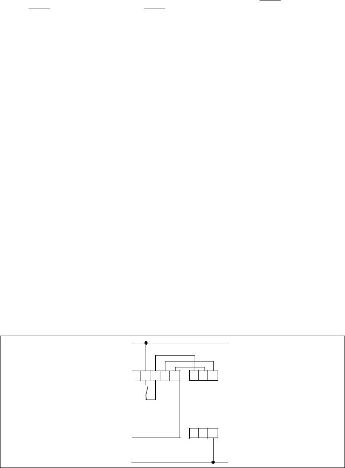
Bitte beachten Sie, dass die Sicherheitsfunktionen des bestehenden Stromkreises nur erhalten bleiben, wenn der Kontaktblock wie in Fig. 2 gezeigt angeschlossen wird. Es können nur Grundgeräte mit Rückführkreis verwendet werden.
Das Gerät nur wie in der folgenden Abbildung dargestellt anschließen!
Operation
Please note for operation
•To prevent contact welding, a fuse (see technical details) must be connected in front of the output contacts.
•Calculating the max. cable length Imax at the input circuit and feedback loop:
Imax = Rlmax
Rl / km
Rlmax = max. overall cable resistance (see technical details)
Rl /km = cable resistance/km
•Low currents should not be switched across contacts across which high currents have previously been switched.
•Use copper wire that can withstand temperatures of 60/75°C
•Important details in the section “Technical
Data” should be noted and adhered to.
Connection and Setting
•Connect operating voltage to terminals A1(+) and A2(-).
•Input circuit
Connect safety contacts of the base unit to A1
•Feedback control loop
Connect Y1 and Y2 with the feedback control loop of the base unit.
To operate
The unit is activated when:
•the safety contact connected to A1 is closed
•the operating voltage is applied
The LEDs “CH.1” and “CH.2” are illuminated; the safety contacts 13-14, 2324, 33-34, 43-44 (PZE X4) or 17-18, 27-28,
37-38, 47-48 (PZE X4V) are closed.
If the input circuit is opened, the safety contacts (see above) open immediately (PZE X4) or after the delayed time has elapsed (PZE X4V).
Reactivation
Close the input circuit.
Application
Please note that the safety functions of the existing circuit are only maintained when the contact block is connected as shown in
Fig. 2. Only base units with the feedback control loop may be used.
Only connect the unit as shown in the following example
Mise en oeuvre
Remarques préliminaires :
•Protéger les contacts de sortie par des fusibles (voir les caractéristiques techniques) pour éviter leur soudage
•Calcul de la longueur de conducteur Imax sur le circuit d’entrée et boucle de retour :
Imax = Rlmax
Rl / km
Rlmax = Résistivité de câblage totale max.
(voir les caractéristiques techniques) Rl /km = résistance du câble/km
•Ne pas commuter de faibles intensités par des contacts ayant au préalable commutés des intensité plus élevées.
•Utiliser des câbles en cuivre supportant des températures de 60/75°C
•Respecter les données indiquées dans le chapitre „Caractéristiques techniques“.
Branchement et réglage
•Ramener la tension d'alimentation 24 VDC sur les bornes A1(+) (par l'intermédiare d'un contact de l'appareil de base) et
A2 (-).
•Circuit d'entrée
Câbler le contact de l'appareil de base sur A1
•Boucle de retour
Relier les bornes Y1 et Y2 à la boucle de retour de l'appareil de base.
Mise en oeuvre
L'appareil est activé si :
•le contact de commande sur A1 est fermé
•la tension d'alimentation 24 VCC est présente.
Les LEDs "CH.1" et "CH.2" sont allumées;les contacts de sécurité 13-14, 23-24, 33-34 et 43-44 (PZE X4) ou 17-18, 27-28, 37-38 et
47-48 (PZE X4V) se ferment.
Si le circuit d'entrée est ouvert, les relais K1 et K2 retombent instantanément (PZE X4) ou après écoulement de la temporisa-
tion (PZE X4V). Les contacts de sécurité s'ouvrent.
Réarmement
Refermer le circuit d'entrée
Utilisation
Le niveau de sécurité des contacts des blocs d'extension n'est garanti que si le relais est câblé comme représenté dans la figure ci-dessous (Fig. 2). Seuls des blocs logiques avec une boucle de retour peuvent être utilisés.
Câbler uniquement le relais comme indiqué ci-dessous !
UB
13 |
14 |
Y2 |
Y1 |
A1 |
Y1 |
Y2 |
Grundgerät |
|
|
|
|
|
|
Base unit |
|
|
PZE X4 |
|
||
Appareil de base |
|
PZE X4V |
|
|||
|
|
|
|
|
|
A2 |
Fig. 2: PZE X4/X4V - |
|
Anschlussbild |
|
Connection Diagram |
|
Schéma de branchement |
0 V |
|
- 3 -

Fehler - Störungen
Durch Schließen bzw. Unterbrechen des Eingangskreises kann überprüft werden, ob das Gerät ordnungsgemäß einbzw. ausschaltet.
Das Gerät kann aus Sicherheitsgründen bei folgenden Fehlern nicht gestartet werden:
•Fehlfunktion der Kontakte:
Da der Kontaktblock mit einem Grundgerät verschaltet wird, ist bei verschweißten Kontakten nach Öffnen des Eingangskreises keine neue Aktivierung möglich.
•Leitungsunterbrechung, Kurzoder
Erdschluss (z. B. im Eingangskreis)
Faults - Disturbances
By closing/interrupting the input circuit, the correct de-energisation/energisation of the unit can be tested.
For safety reasons, the unit cannot be activated if the following faults are present:
•Faulty contact functions:
As the contact block is wired to a base unit, in the case of welded contacts no further activation is possible following an opening of the input circuit.
•Cable break, short-circuit or earth fault (e.g. in the input circuit).
Test - Sources d'erreur
Le bon fonctionnement du relais peut être vérifié en ouvrant et en refermant les canaux d'entrée.
Pour garantir la fonction de sécurité, le relais n'est pas réarmé en cas des défauts suivants:
•Défaillance d'un contact interne :
En cas de soudage d'un contact interne, un nouvel réarmement du relais est impossible
(le relais doit être relié à un appareil de base).
•Coupure d'un canal d'entrée, court-circuit ou défaut de masse dans les canaux d'entrée sont détectés.
Technische Daten |
Technical Data |
Caractéristiques techniques |
|
|
|
|
|
Elektrische Daten |
Electrical data |
Données électriques |
|
Versorgungsspannung UB |
Supply Voltage UB |
Tension d’alimentation UB |
DC: 24 V |
Spannungstoleranz |
Voltage Tolerance |
Plage de la tension d’alimentation |
-15 ... +10 % |
|
|
|
|
Leistungsaufnahme bei UB |
Power consumption at UB |
Consommation pour UB |
2,5 W |
Restwelligkeit |
Residual Ripple |
Ondulation résiduelle |
DC: 20 % |
Spannung und Strom an |
Voltage and Current at |
Tension et courant du |
|
Eingangskreis |
Input circuit |
Circuit d’entrée |
24 V DC: 95 mA |
Anzahl der Ausgangskontakte |
Number of output contacts |
Nombre de contacts de sortie |
Sicherheitskontakte (S) |
Safety contacts (N/O) |
contacts de sécurité (F) |
PZE X4: |
PZE X4: |
PZE X4: |
PZE X4V: |
PZE X4V: |
PZE X4V: |
PZE X4: |
PZE X4: |
PZE X4: |
Gebrauchskategorie nach |
Utilization category in accordance with |
Catégorie d’utilisation selon |
EN 60947-4-1 |
EN 60947-4-1 |
EN 60947-4-1 |
EN 60947-5-1(DC13: |
EN 60947-5-1(DC13: 6 cycles/min) |
EN 60947-5-1(DC13: |
6 Schaltspiele/Min.) |
|
6 manoeuvres/min) |
PZE X4V: |
PZE X4V: |
PZE X4V: |
Gebrauchskategorie nach |
Utilization category in accordance with |
Catégorie d’utilisation selon |
EN 60947-4-1 |
EN 60947-4-1 |
EN 60947-4-1 |
EN 60947-5-1(DC13: |
EN 60947-5-1(DC13: 6 cycles/min) |
EN 60947-5-1(DC13: |
6 Schaltspiele/Min.) |
|
6 manoeuvres/min) |
Kontaktmaterial |
Contact material |
Matériau contact |
PZE X4: |
PZE X4: |
PZE X4: |
Kontaktabsicherung extern |
External contact fuse protection |
Protection des contacts externe |
EN 60947-5-1 (IK = 1 kA) |
EN 60947-5-1 (IK = 1 kA) |
EN 60947-5-1 (IK = 1 kA) |
Schmelzsicherung flink |
Blow-out fuse quick |
Fusibles rapide |
Schmelzsicherung träge |
Blow-out fuse slow |
Fusibles normal |
Sicherungsautomat |
Safety cut-out |
Dijoncteur |
Charakteristik |
Characteristic |
Caractéristique |
PZE X4V: |
PZE X4V: |
PZE X4V: |
Kontaktabsicherung extern |
External contact fuse protection |
Protection des contacts externe |
EN 60947-5-1 (IK = 1 kA) |
EN 60947-5-1 (IK = 1 kA) |
EN 60947-5-1 (IK = 1 kA) |
Schmelzsicherung flink |
Blow-out fuse quick |
Fusibles rapide |
Schmelzsicherung träge |
Blow-out fuse slow |
Fusibles normal |
Sicherungsautomat |
Safety cut-out |
Dijoncteur |
Charakteristik |
Characteristic |
Caractéristique |
Max. Gesamtleitungswiderstand Rlmax Max. overall cable resistance Rlmax |
Résistance de câblage totale max. |
|
Eingangskreise |
input circuits |
Rlmax circuits d'entrée |
einkanalig DC |
Single-channel DC |
Commande par 1 canal DC |
4
4
AC1: 240 V/0,01 ... 6 A/ 1500 VA
DC1: 24 V/0,01 ... 6 A/ 150 W
AC15: 230 V/5 A;
DC13: 24 V/5 A
AC1: 240 V/0,01 ... 6A/ 1500 VA
DC1: 24 V/0,01 ... 6 A/ 150 W
AC15: 230 V/3 A
DC13: 24 V/4 A
AgCuNi+ 0,2 µm Au
10 A
6 A
24 V AC/DC: 6 A B/C
6 A
4 A
24 V AC/DC: 4 A B/C
30 Ohm
Sicherheitstechnische Kenndaten |
Safety-related characteristics of |
Caractéristiques techniques de |
der Sicherheitsausgänge |
the safety outputs |
sécurité des sorties de sécurité |
PL nach EN ISO 13849-1 |
PL in accordance with |
PL selon EN ISO 13849-1 |
|
EN ISO 13849-1 |
|
PZE X4: |
PZE X4: |
PZE X4: |
PZE X4V: |
PZE X4V: |
PZE X4V: |
Kategorie nach EN 954-1 |
Category in accordance with |
Catégorie selon EN 954-1 |
|
EN 954-1 |
|
PZE X4: |
PZE X4: |
PZE X4: |
PZE X4V: |
PZE X4V: |
PZE X4V: |
SIL CL nach EN IEC 62061 |
SIL CL in accordance with |
SIL CL selon EN IEC 62061 |
|
EN IEC 62061 |
|
PZE X4: |
PZE X4: |
PZE X4: |
PZE X4V: |
PZE X4V: |
PZE X4V: |
PL e (Cat. 4)
PL d (Cat. 3)
Cat. 4
Cat. 3
SIL CL 3
SIL CL 2
- 4 -

PFH nach EN IEC 62061 |
PFH in accordance with |
PFH selon EN IEC 62061 |
|
|
EN IEC 62061 |
|
|
PZE X4: |
PZE X4: |
PZE X4: |
2,31E-09 |
PZE X4V: |
PZE X4V: |
PZE X4V: |
2,48E-09 |
SIL nach IEC 61511 |
SIL in accordance with IEC 61511 |
SIL selon IEC 61511 |
|
PZE X4: |
PZE X4: |
PZE X4: |
SIL 3 |
PZE X4V: |
PZE X4V: |
PZE X4V: |
SIL 2 |
PFD nach IEC 61511 |
PFD in accordance with IEC 61511 |
PFD selon IEC 61511 |
|
PZE X4: |
PZE X4: |
PZE X4: |
2,03E-06 |
PZE X4V: |
PZE X4V: |
PZE X4V: |
1,47E-05 |
tM in Jahren |
tM in years |
tM en années |
20 |
Zeiten |
Times |
Temporisations |
|
Einschaltverzögerung |
Switch-on delay |
Temps de réarmement |
|
PZE X4: |
PZE X4: |
PZE X4: |
typ. 30 ms, max. 50 ms |
PZE X4V: |
PZE X4V: |
PZE X4V: |
typ. 55 ms, max. 200 ms |
Rückfallverzögerung |
Delay-on De-Energisation |
Temps de retombée |
|
PZE X4: |
PZE X4: |
PZE X4: |
typ.: 30 ms, max.: 50 ms |
PZE X4V: |
PZE X4V: |
PZE X4V: |
typ. 0,50 s |
|
|
|
typ. 0,75 s |
|
|
|
typ. 1,00 s |
|
|
|
typ. 2,00 s |
|
|
|
typ. 3,00 s |
Toleranz PZE X4V |
Tolerance PZE X4V |
Tolérance PZE X4V |
-50 % / +50 % |
Überbrückung bei |
Supply interruption before de- |
Tenue aux micro-coupures |
|
Spannungseinbrüchen |
energisation |
|
20 ms |
Umweltdaten |
Environmental data |
Données sur l'environnement |
|
EMV |
EMC |
CEM |
EN 60947-5-1, |
|
|
|
EN 61000-6-2 |
Schwingungen nach EN 60068-2-6 |
Vibration to EN 60068-2-6 |
Vibrations selon EN 60068-2-6 |
|
Frequenz |
Frequency |
Frequence |
10 ... 55 Hz |
Amplitude |
Amplitude |
Amplitude |
0,35 mm |
Klimabeanspruchung |
Climate Suitability |
Conditions climatiques |
EN 60068-2-78 |
Luftund Kriechstrecken nach |
Airgap Creepage in accordance with |
Cheminement et claquage selon |
|
EN 60947-1 |
EN 60947-1 |
EN 60947-1 |
|
Verschmutzungsgrad |
Pollution degree |
Niveau d'encrassement |
2 |
Überspannungskategorie |
Overvoltage category |
Catégorie de surtensions |
III |
Bemessungsisolationsspannung |
Rated insulation voltage |
Tension assignée d'isolement |
250 V |
Bemessungsstoßspannungs- |
Rated impulse withstand voltage |
Tension assignée de tenue aux |
|
festigkeit |
|
chocs |
|
PZE X4: |
PZE X4: |
PZE X4: |
6 kV |
PZE X4V: |
PZE X4V: |
PZE X4V: |
4 kV |
Umgebungstemperatur |
Ambient temperature |
Température d’utilisation |
-10 ... + 55 °C |
Lagertemperatur |
Storage temperature |
Température de stockage |
-40 ... +85 °C |
Schutzart |
Protection type |
Indice de protection |
|
Einbauraum (z. B. Schaltschrank) |
Mounting (eg. panel) |
Lieu d'implantation (ex. armoire) |
IP54 |
Gehäuse |
Housing |
Boîtier |
IP40 |
Klemmenbereich |
Terminals |
Bornes |
IP20 |
Mechanische Daten |
Mechanical data |
Données mécaniques |
|
Gehäusematerial |
Housing material |
Matériau du boîtier |
|
Gehäuse |
Housing |
Boîtier |
PPO UL 94 V0 |
Front |
Front panel |
Face avant |
ABS UL 94 V0 |
Querschnitt des Außenleiters |
Cable cross section (screw |
Capacité de raccordement (borniers |
|
(Schraubklemmen) |
terminals) |
à vis) |
|
1 Leiter, flexibel |
1 core, flexible |
1 conducteur souple |
0,2 ... 4,0 mm2, 24 - 10 AWG |
2 Leiter gleichen Querschnitts, flexi- |
2 core, same cross section flexible |
2 conducteurs de même diamètre |
|
bel mit Aderendhülse, ohne |
with crimp connectors, without |
souple avec embout, sans chapeau |
|
Kunststoffhülse |
insulating sleeve |
plastique |
0,2 ... 2,5 mm2, 24 - 14 AWG |
ohne Aderendhülse oder mit TWIN- |
without crimp connectors or with |
souple sans embout ou avec |
|
Aderendhülse |
TWIN crimp connectors |
embout TWIN |
0,2 ... 2,5 mm2, 24 - 14 AWG |
Anzugsdrehmoment für |
Torque setting for screw terminals |
Couple de serrage (borniers à vis) |
|
Schraubklemmen |
|
|
0,6 Nm |
Abmessungen H x B x T |
Dimensions H x W x D |
Dimensions H x P x L |
87 x 22,5 x 121 mm |
Einbaulage |
Fitting Position |
Position de travail |
beliebig/any/indifférente |
Gewicht |
Weight |
Poids |
|
PZE X4: |
PZE X4: |
PZE X4: |
175 g |
PZE X4V: |
PZE X4V: |
PZE X4V: |
205 g |
Es gelten die 2009-12 aktuellen Ausgaben der Normen.
The version of the standards current at 2009-12 shall apply.
Se référer à la version des normes en vigeur au 2009-12.
- 5 -
 Loading...