


 Loading...
PMI 5
Operator terminals
Operating Manual1002241EN05
This document is a translation of the original document.
All rights to this documentation are reserved by Pilz GmbH & Co. KG. Copies may be made for internal purposes. Suggestions and comments for improving this documentation will be gratefully received.
Pilz®, PIT®, PMI®, PNOZ®, Primo®, PSEN®, PSS®, PVIS®, SafetyBUS p®, SafetyEYE®, SafetyNET p®, the spirit of safety® are registered and protected trademarks of Pilz GmbH & Co. KG in some countries.
 SD means Secure Digital

Content
Section 1 |
Introduction |
5 |
|
|
1.1 |
Validity of the documentation |
5 |
|
1.1.1 |
Retaining the documentation |
5 |
|
1.2 |
Definition of symbols |
6 |
Section 2 |
Overview |
7 |
|
|
2.1 |
Unit structure |
7 |
|
2.1.1 |
Unit features |
7 |
|
2.2 |
Front view |
8 |
|
2.2.1 |
PMI 509 |
8 |
|
2.2.2 |
PMI 515/PMI 516/PMI 518/PMI 526/PMI 531/PMI 538 |
9 |
|
2.3 |
Scope of supply |
9 |
Section 3 |
Safety |
|
11 |
|
3.1 |
Intended use |
11 |
|
3.2 |
Safety regulations |
11 |
|
3.2.1 |
Use of qualified personnel |
11 |
|
3.2.2 |
Warranty and liability |
12 |
|
3.2.3 |
Disposal |
12 |
|
3.3 |
Unitspecific safety regulations |
12 |
|
3.3.1 |
Installation site |
12 |
|
3.3.2 |
Measures to protect against interference |
12 |
|
3.3.3 |
Supply voltage |
12 |
|
3.3.4 |
Operation |
13 |
|
3.3.5 |
Maintenance |
13 |
Section 4 |
Function description |
14 |
|
|
4.1 |
Features |
14 |
|
4.2 |
Side views |
15 |
|
4.2.1 |
PMI 509 |
15 |
|
4.2.2 |
PMI 515 |
16 |
|
4.2.3 |
PMI 516/PMI 518/PMI 526/PMI 531/ PMI 538 |
17 |
Section 5 |
Installation |
18 |
|
|
5.1 |
Safety |
18 |
|
5.1.1 |
Installation site and unit surroundings |
18 |
|
5.2 |
PMI 509 nominal sizes |
19 |
|
5.3 |
PMI 515 nominal sizes |
20 |
|
5.4 |
PMI 516/PMI 518/PMI 526/PMI 531/PMI 538 nominal sizes |
21 |
|
5.5 |
Installing the unit |
22 |
|
5.6 |
PMI 509 Installation |
22 |
|
5.7 |
PMI 515 Installation |
23 |
|
5.8 |
Installing the PMI 516/PMI 518/PMI 526/PMI 531/PMI 538 |
24 |
Section 6 |
Wiring |
|
25 |
|
|
|
6.1 |
General wiring guidelines |
25 |
|
|
6.1.1 |
Shielding |
25 |
|
|
6.1.2 |
Measures to protect against interference voltages |
25 |
|
|
|
|
|
Operating Manual PMI 5 |
|
3 |
||
1002241EN05 |
|
|
|
|

Content
|
6.2 |
Connecting the Unit |
26 |
|
6.2.1 |
Supply voltage |
26 |
|
6.2.2 |
Connection example |
26 |
|
6.2.3 |
Interfaces |
27 |
|
|
|
|
Section 7 |
Putting into Service |
28 |
|
|
7.1 |
Activating the setup |
28 |
|
7.2 |
Control Panel |
28 |
|
7.2.1 |
Backup and restore |
29 |
|
7.2.2 |
Password settings |
29 |
|
|
|
|
Section 8 |
Care and Maintenance |
32 |
|
|
8.1 |
Cleaning the touchscreen |
32 |
|
|
|
|
Section 9 |
Attachment |
33 |
|
|
9.1 |
Supported Windows components |
33 |
|
9.2 |
Windows CE Shell commands |
39 |
|
9.3 |
Windows CE Shell commands Pilz expansions |
42 |
|
|
|
|
Section 10 |
Technical details |
47 |
|
|
|
|
|
Section 11 |
Order reference |
51 |
|
Operating Manual PMI 5 |
4 |
1002241EN05 |
|

Introduction
1 Introduction
1.1Validity of the documentation
This operating manual is valid for the following products:
}PMI 509
}PMI 515
}PMI 516
}PMI 518
}PMI 526
}PMI 531
}PMI 538
This operating manual explains the function and operation, describes the installation and provides guidelines on how to connect the product.
1.1.1Retaining the documentation
This documentation is intended for instruction and should be retained for future reference.
Operating Manual PMI 5 |
5 |
1002241EN05 |
|
Introduction
1.2Definition of symbols
Information that is particularly important is identified as follows:
DANGER!
This warning must be heeded! It warns of a hazardous situation that poses an immediate threat of serious injury and death and indicates preventive measures that can be taken.
WARNING!
This warning must be heeded! It warns of a hazardous situation that could lead to serious injury and death and indicates preventive measures that can be taken.
CAUTION!
This refers to a hazard that can lead to a less serious or minor injury plus material damage, and also provides information on preventive measures that can be taken.
NOTICE
This describes a situation in which the product or devices could be dam aged and also provides information on preventive measures that can be taken. It also highlights areas within the text that are of particular import ance.
INFORMATION
This gives advice on applications and provides information on special fea tures.
Operating Manual PMI 5 |
6 |
1002241EN05 |
|

Overview
2 Overview
2.1Unit structure
The PMI is an operator terminal that is used to operate and monitor technical processes.
2.1.1Unit features
}Analogue resistive touchscreen
}Character set: Unicode
}PMI 509: in addition
–4 function keys (F1 … F4) and
–4 system keys (ESC, ENTER, cursor up, cursor down)
}Memory:
256 MB DDR SDRAM
512 MB Flash
}1 serial interface
}1 Ethernet Interface
}1 USB slave interface
}1 USB host interface (PMI 509/PMI 515)
2 USB host interfaces (PMI 516/PMI 518/PMI 526/PMI 531/PMI 538)
}Batterybuffered realtime clock
}Userspecific applications and various visualisation software packages can be installed
Operating Manual PMI 5 |
7 |
1002241EN05 |
|

Overview
2.2Front view
2.2.1 |
PMI 509 |
|
|
|
1 |
2 |
3 |
Fig.: Front view PMI 509
Legend:
}1: F1 ... F4 (function keys)
}2: Touchscreen (see "Technical Details")
}3: ESC, ENTER, cursor up, cursor down
The key allocation is predefined by the operating system, the configuration can be changed as desired.
Operating Manual PMI 5 |
8 |
1002241EN05 |
|

Overview
2.2.2PMI 515/PMI 516/PMI 518/PMI 526/PMI 531/PMI 538
1 |
Fig.: Front view of PMI 515/PMI 516/PMI 518/PMI 526/PMI 531/PMI 538 |
Legend:
} 1: Touchscreen (see "Technical details")
2.3Scope of supply
PMI 509
}Operator terminal
}2 retaining clamps
}Connector plug for power supply
}Projection stands
}Device documentation on CD/DVD
PMI 515
}Operator terminal
}Cover plate
Operating Manual PMI 5 |
9 |
1002241EN05 |
|

Overview
}Connector plug for power supply
}Projection stands
}Device documentation on CD/DVD
PMI 516/PMI 518/PMI 526/PMI 531/ PMI 538
}Operator terminal
}Retaining clamps
}Connector plug for power supply
}Projection stands
}Device documentation on CD/DVD
Operating Manual PMI 5 |
10 |
1002241EN05 |
|
Safety
3 Safety
3.1Intended use
This device is used to operate and monitor technical processes.
The PMI offers the possibility of installing software from thirdparty suppliers. Pilz GmbH & Co. KG accepts no liability for any damages, nor does it provide support or any guarantee for the functional efficiency of the installed software.
INFORMATION
Ensure that the graphics software is suitable for the ARMV4i processor type and the Windows CE 6.0 embedded operating system.
CAUTION!
The unit is not designed for use in applications with stringent safety require ments (e.g. ESTOP).
Intended use includes making the electrical installation EMCcompliant. The product is de signed for use in an industrial environment. It is not suitable for use in a domestic environ ment, as this can lead to interference.
The following is deemed improper use in particular:
}Any component, technical or electrical modification to the product
}Use of the product outside the areas described in this manual
}Use of the product outside the technical details (see chapter entitled “Technical De tails”)
3.2Safety regulations
3.2.1Use of qualified personnel
The products may only be assembled, installed, programmed, commissioned, operated, maintained and decommissioned by competent persons.
A competent person is someone who, because of their training, experience and current pro fessional activity, has the specialist knowledge required to test, assess and operate the work equipment, devices, systems, plant and machinery in accordance with the general standards and guidelines for safety technology.
It is the company’s responsibility only to employ personnel who:
}Are familiar with the basic regulations concerning health and safety / accident preven tion
}Have read and understood the information provided in this description under "Safety"
}And have a good knowledge of the generic and specialist standards applicable to the specific application.
Operating Manual PMI 5 |
11 |
1002241EN05 |
|

Safety
3.2.2Warranty and liability
All claims to warranty and liability will be rendered invalid if
}The product was used contrary to the purpose for which it is intended
}Damage can be attributed to not having followed the guidelines in the manual
}Operating personnel are not suitably qualified
}Any type of modification has been made (e.g. exchanging components on the PCB boards, soldering work etc.).
3.2.3Disposal
}When decommissioning, please comply with local regulations regarding the disposal of electronic devices (e.g. Electrical and Electronic Equipment Act).
3.3Unitspecific safety regulations
Before you install or commission the system, you should refer to any guidelines laid down by the control manufacturer or operator.
3.3.1Installation site
}Do not position PMI close to highly flammable materials.
}When installing the unit within a control cabinet, you must ensure the ventilation slots are not obstructed, otherwise the unit could be damaged through overheating.
}Protect the unit from direct sunlight and dust.
3.3.2Measures to protect against interference
}If necessary, use bulkhead separators to protect the unit from sources of interference.
}Inductive loads within the environment (e.g. contactor, relay and solenoid valve coils) should be wired using suppression elements (e.g. RC elements). This is particularly im portant if these inductive loads are fed from the same supply.
}The power cables and the data cables should be physically separated from each other in their own conduits (recommended minimum distance: 10 cm/3.94"). This will avoid in ductive and capacitive interference.
}The prescribed earth point  for the functional earth guarantees compliance with noise immunity requirements.
Connect the functional earth to the central earth point in star form. A cable cross sec tion of at least 1.5 mm² should be used for the connection. Connections should be kept as short as possible.
3.3.3Supply voltage
}The supply voltage must be +24 V DC
Operating Manual PMI 5 |
12 |
1002241EN05 |
|

Safety
CAUTION!
Safe electrical isolation must be ensured for the external power supply gen erating the 24 V voltage supply. Failure to do so could result in electric shock. Power supplies must conform to DIN VDE 0551/EN 60742 and
EN 50178.
3.3.4Operation
}Plan the system correctly to ensure that a communication error between the PMI and the host computer does not cause a malfunction.
}Do not operate the touchscreen interface using hard or heavy objects or apply excess ive pressure.
}The maximum ambient temperature must not be exceeded when using the unit.
}Do not pour liquids over the unit or insert any objects into the unit.
}When in storage and during operation, protect the unit from vibration and shock.
}Avoid using chemicals close to the system.
3.3.5Maintenance
}Do not use thinners or organic solvents to clean the unit and touchscreen surface.
NOTICE
The touchscreen surface is not abrasion resistant; if it is dirty, please clean with care and do not apply heavy pressure.
Further information on care and maintenance of the touchscreen can be found in the chapter "Care and Maintenance".
Operating Manual PMI 5 |
13 |
1002241EN05 |
|

Function description
4 |
Function description |
4.1Features
The operator terminal has a memory in which graphics display software can be installed. With the help of this software, processes can be shown on the display and directly influ enced via the touchscreen. An Ethernet interface is available for the transfer of data, e.g. diagnostic data, and for communication with other subscribers.
The PMI 509 has additional buttons which can be used to control special functions within an application.
The device is fitted with a realtime clock that is batterybuffered, so allowing it to run for 90 days without an external power supply. The battery is automatically charged during normal operation by the power supply for the device.
Operating Manual PMI 5 |
14 |
1002241EN05 |
|

Function description
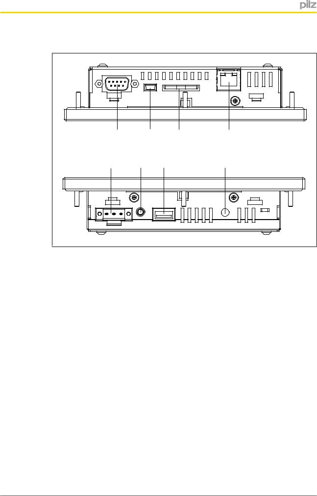
4.2Side views
4.2.1 |
PMI 509 |
|
|
|
|
1 |
2 |
3 |
4 |
|
5 |
6 |
7 |
8 |
Fig.: Side view of PMI 509
Legend
}1: Serial interface COM1 (RS232)
}2: USB slave
}3: SD/SDHC card
}4: Ethernet interface (100 BaseTX)
}5: Supply voltage +24 V DC
}6: Audio interface LINE OUT
}7: USB host
}8: Functional earth
Operating Manual PMI 5 |
15 |
1002241EN05 |
|
Function description
4.2.2 |
PMI 515 |
|
|
|
|
1 |
2 |
3 |
4 |
|
5 |
6 |
7 |
8 |
Fig.: Side view of PMI 515
Legend
}1: Serial interface COM1 (RS232)
}2: USB slave
}3: SD/SDHC card
}4: Ethernet interface (100 BaseTX)
}5: Supply voltage +24 V DC
}6: Audio interface LINE OUT
}7: USB host
}8: Functional earth
Operating Manual PMI 5 |
16 |
1002241EN05 |
|
Loading...