


 Loading...
PNOZ s6
Safety relays
Operating Manual-21398-EN-08
This document is the original document.
All rights to this documentation are reserved by Pilz GmbH & Co. KG. Copies may be made for internal purposes. Suggestions and comments for improving this documentation will be gratefully received.
Pilz®, PIT®, PMI®, PNOZ®, Primo®, PSEN®, PSS®, PVIS®, SafetyBUS p®, SafetyEYE®, SafetyNET p®, the spirit of safety® are registered and protected trademarks of Pilz GmbH & Co. KG in some countries.
 SD means Secure Digital

PNOZ s6
PNOZ s6 safety relay
The two-hand control relay meets the requirements of EN 574 Type IIIC. It forces the operator to keep his hands outside the danger zone area during the hazardous movement. The unit is suitable for use on controllers for metalworking presses as a component for simultaneous switching.
It can be used in applications with
}Mechanical presses (EN 692)
}Hydraulic presses (EN 693)
}Safety circuits in accordance with EN 60204-1
For your safety
}Only install and commission the unit if you have read and understood these operating instructions and are familiar with the applicable regulations for health and safety at work and accident prevention.
Ensure VDE and local regulations are met, especially those relating to safety.
}Any guarantee is rendered invalid if the housing is opened or unauthorised modifications are carried out.
}The two-hand circuit and the connected parts of the press control must conform to the relevant safety standards EN 574, EN 692 and EN 693
}To avoid inductive and capacitance coupling, the cables between the two-hand relay and the pushbuttons must be run separately to any power cables.
}On account of the low currents you should use gold-plated pushbutton contacts.
Unit features
}Positive-guided relay outputs:
–3 safety contacts (N/O), instantaneous
–1 auxiliary contact (N/C), instantaneous
}1 semiconductor output
}Connection options for:
–2 control elements (pushbuttons)
}A connector can be used to connect 1 PNOZsigma contact expansion module
}LED for:
–Supply voltage
–Input status, channel 1
–Input status, channel 2
–Switch status of the safety contacts
–Feedback loop
–Fault
}Plug-in connection terminals (either spring-loaded terminal or screw terminal)
Operating Manual PNOZ s6 |
3 |
21398-EN-08 |
|
PNOZ s6
Safety features
The two-hand control relay meets the following safety requirements:
}The circuit is redundant with built-in self-monitoring
}The safety function remains effective in the case of a component failure
}The circuit prevents a further press stroke in the case of:
–Relay failure
–Contact welding
–Coil defect on a relay
–Open circuit
–Short circuit
}The unit has an electronic fuse.
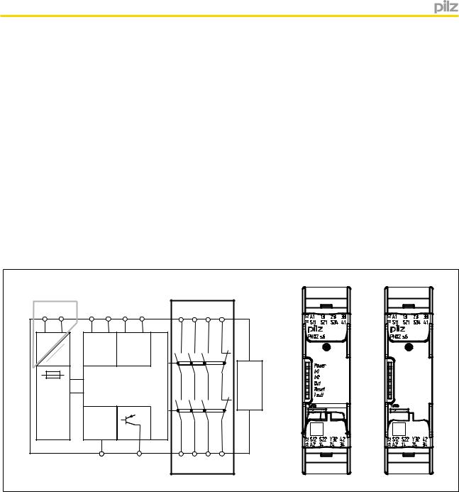
Block diagram/terminal configuration
A1 |
A2 |
* S11 S12 S21 S22 |
13 |
23 |
33 |
41 |
* |
|
= |
) |
Input |
Input |
|
|
|
|
|
(~) |
= |
|
|
|
|
|
||
( |
|
|
K1 |
|
|
|
Interface expansion unit |
|
Power |
|
|
|
|
|
|
||
|
|
|
|
|
|
|
|
|
|
|
Feed- |
|
K2 |
|
|
|
|
|
|
|
|
|
|
|
|
|
|
|
back |
|
|
|
|
|
|
|
|
(Reset) |
|
|
|
|
|
|
|
|
S34 |
Y32 |
14 |
24 |
34 |
42 |
|
Centre: Front view with cover, right: Front view without cover
Grey highlighted area: Applies only with UB = 48 – 240 V AC/DC
*Insulation between the non-marked area and the relay contacts: Basic insulation (overvoltage category III), safe separation (overvoltage category II)
Function description
}The two-hand control relay must be activated by simultaneously pressing two buttons within0,5 s . If one or both of the buttons are released, the unit interrupts the control command for the hazardous movement.
}Reactivation: The output relays will not re-energise until both operator elements have been released and then re-operated simultaneously.
Operating Manual PNOZ s6 |
4 |
21398-EN-08 |
|
PNOZ s6
Installation
Install base unit without contact expansion module:
}Ensure that the plug terminator is inserted at the side of the unit.
Connect base unit and PNOZsigma contact expansion module:
}Remove the plug terminator at the side of the base unit and at the contact expansion module.
}Connect the base unit and the contact expansion module to the supplied connector before mounting the units to the DIN rail.
Installation in control cabinet
}The safety relay should be installed in a control cabinet with a protection type of at least IP54.
}Use the notch on the rear of the unit to attach it to a DIN rail (35 mm).
}When installed vertically: Secure the unit by using a fixing element (e.g. retaining bracket or end angle).
}Push the device upwards or downwards before lifting it from the DIN rail.
Wiring
Please note:
}Information given in the "Technical details" must be followed.
}Outputs 13-14, 23-24, 33-34 are safety contacts; output 41-42 is an auxiliary contact (e.g. for display).
}Auxiliary contact 41-42 and semiconductor output Y32 should not be used for safety circuits!
}To prevent contact welding, a fuse should be connected before the output contacts (see technical details).
}Calculation of the max. cable length lmax in the input circuit:
Imax = Rlmax
Rl / km
Rlmax = max. overall cable resistance (see technical details)
Rl / km = cable resistance/km
}Use copper wire that can withstand 60/75 °C.
}Sufficient fuse protection must be provided on all output contacts with capacitive and inductive loads.
Operating Manual PNOZ s6 |
5 |
21398-EN-08 |
|

PNOZ s6
Preparing for operation
}Supply voltage
Supply voltage |
AC |
|
|
DC |
|
|
|
A1 |
L |
A1 |
L+ |
|
S22 |
A2 |
N |
A2 |
L- |
}Input circuit
Input circuit |
Single-channel |
Dual-channel |
|
Two-hand pushbuttons |
|
S11 |
S1 |
with detection of shorts |
|
|
|
|
|
|
|
across contacts |
|
S21 |
S2 |
|
|
|
|
|
|
S12(+) |
|
|
|
S22(-) |
|
}Feedback loop
|
Feedback loop |
|
|
|
Contacts from external con- |
S12 |
|
|
|
tactors |
K5 |
K6 |
|
|
S34 |
|
|||
|
13 (23,33) |
|
K5 |
L1 |
|
14 (24,34) |
|
N |
|
|
|
|
||
|
|
|
K6 |
|
}Semiconductor output
Legend
}S1/S2: Two-hand pushbuttons
Operation
The unit is ready for operation when the Power LED is permanently lit.
LEDs indicate the status and errors during operation:
LED on
LED flashes
Operating Manual PNOZ s6 |
6 |
21398-EN-08 |
|
Loading...