


19907-6NL-05
PNOZ X3P
4
D Betriebsanleitung
4
GB Operating instructions
4
F Manuel d'utilisation
4 E Instrucciones de uso
4 I Istruzioni per l`uso
4 NL Gebruiksaanwijzing
Sicherheitsbestimmungen
• Das Gerät darf nur von Personen installiert
und in Betrieb genommen werden, die mit
dieser Betriebsanleitung und den geltenden
Vorschriften über Arbeitssicherheit und
Unfallverhütung vertraut sind. Beachten Sie
die VDE- sowie die örtlichen Vorschriften,
insbesondere hinsichtlich Schutzmaßnahmen.
• Beim Transport, der Lagerung und im
Betrieb die Bedingungen nach EN 60068-26 einhalten (s. technische Daten).
• Durch Öffnen des Gehäuses oder eigenmächtige Umbauten erlischt jegliche Gewährleistung.
• Montieren Sie das Gerät in einen Schaltschrank; Staub und Feuchtigkeit können
sonst zu Beeinträchtigungen der Funktionen führen.
• Sorgen Sie an allen Ausgangskontakten bei
kapazitiven und induktiven Lasten für eine
ausreichende Schutzbeschaltung.
• Hinweis für Überspannungskategorie III:
Wenn am Gerät höhere Spannungen als
Kleinspannung (>50 V AC oder
>120 V DC) anliegen, müssen angeschlossene Bedienelemente und Sensoren eine
Bemessungsisolationsspannung von mind.
250 V aufweisen.
Safety Regulations
• The unit may only be installed and
operated by personnel who are familiar
with both these instructions and the current
regulations for safety at work and accident
prevention. Follow VDE and local
regulations especially as regards
preventative measures.
• Transport, storage and operating conditions
should all conform to EN 60068-2-6.
• Any guarantee is void following opening of
the housing or unauthorised modifications.
• The unit should be panel mounted,
otherwise dampness or dust could lead to
function impairment.
• Adequate protection must be provided on
all output contacts especially with
capacitive and inductive loads.
• Note for overvoltage category III:
If voltages higher than low voltage
(>50 VAC or >120 VDC) are present on
the unit, connected control elements and
sensors must have a rated insulation
voltage of at least 250 V.
Conseils préliminaires
• La mise en oeuvre de l’appareil doit être
effectuée par une personne spécialisée en
installations électriques, en tenant compte
des prescriptions des différentes normes
applicables (NF, EN, VDE...) notamment
au niveau des risques encourus en cas de
défaillance de l’équipement électrique.
• Respecter les exigences de la norme
EN 60068-2-6 lors du transport, du
stockage et de l'utilisation de l'appareil.
• L’ouverture de l’appareil ou sa modification
annule automatiquement la garantie.
• L’appareil doit être monté dans une armoire; l’humidité et la poussière pouvant
entraîner des aléas de fonctionnement.
• Vérifiez que le pouvoir de coupure des
contacts de sortie est suffisant en cas de
circuits capacitifs ou inductifs.
• Remarque relative à la catégorie de
surtensions III :
Si l’appareil est alimenté avec des tensions
supérieures à la basse tension (>50 V AC
ou >120 V DC), les éléments de commande
et les capteurs raccordés doivent supporter
une tension d’isolement assignée d’au
moins 250 V.
Bestimmungsgemäße Verwendung
Das Sicherheitsschaltgerät dient dem
sicherheitsgerichteten Unterbrechen eines
Sicherheitsstromkreises. Das Sicherheitsschaltgerät erfüllt Forderungen der
EN 60947-5-1, EN 60204-1 und
VDE 0113-1 und darf eingesetzt werden in
Anwendungen mit
• Not-Halt-Tastern
• Schutztüren
• Lichtschranken
Gerätebeschreibung
Das Sicherheitsschaltgerät PNOZ X3P ist in
einem P-99-Gehäuse untergebracht. Es kann
mit 24 V Gleichspannung oder Wechselspannung betrieben werden.
Merkmale:
• Relaisausgänge: 3 Sicherheitskontakte
(Schließer) und ein Hilfskontakt (Öffner),
zwangsgeführt
• Anschlussmöglichkeit für Not-Halt-Taster,
Schutztürgrenztaster und Starttaster
• Statusanzeige
• Überwachung externer Schütze möglich
• Halbleiterausgang meldet Betriebsbereitschaft
Das Schaltgerät erfüllt folgende Sicherheitsanforderungen:
• Schaltung ist redundant mit Selbstüberwachung aufgebaut.
• Sicherheitseinrichtung bleibt auch bei
Ausfall eines Bauteils wirksam.
• Bei jedem Ein-Aus-Zyklus der Maschine
wird automatisch überprüft, ob die Relais
der Sicherheitseinrichtung richtig öffnen
und schließen.
• Das Gerät hat eine elektronische Sicherung.
Authorised Applications
The safety relay provides a safety-related
interruption of a safety circuit. The safety
relay meets the requirements of EN 60947-51, EN 60204-1 and VDE 0113-1 and may be
used in applications with
• E-STOP pushbuttons
• Safety gates
• Light barriers
Description
The Safety Relay PNOZ X3P is enclosed in a
45 mm P-99 housing. The unit can be
operated with 24 VAC/DC.
Features:
• Relay outputs: 3 safety contacts (N/O)
and one auxiliary contact (N/C), positiveguided
• Connections for Emergency Stop Button,
Safety Gate Limit Switch and Reset
button
• Status Indicators
• Monitoring of external contactors/relays
possible
• Semi-conductor outputs show ready for
operation
The relay complies with the following safety
requirements:
• The circuit is redundant with built-in selfmonitoring.
• The safety function remains effective in the
case of a component failure.
• The correct opening and closing of the
safety function relays is tested
automatically in each on-off cycle.
• The relays has an electronic fuse.
- 1 -
Domaines d’utilisation
Le bloc logique de sécurité sert à interrompre
en toute sécurité un circuit de sécurité. Le
bloc logique de sécurité satisfait aux
exigences des normes EN 60947-5-1,
EN 60204-1 et VDE 0113-1 et peut être
utilisé dans des applications avec des
• poussoirs d'arrêt d'urgence
• protecteurs mobiles
• barrières immatérielles
Description de l’appareil
Inséré dans un boîtier P-99, le bloc logique
de sécurité PNOZ X3P peut être alimenté en
24 VAC/DC.
Particularités :
• Sorties disponibles : 3 contacts à
fermeture de sécurité et un contact à
ouverture pour signalisation
• Bornes de raccordement pour poussoirs
AU, détecteurs de position et poussoir de
validation
• LEDs de visualisation
• Auto-contrôle possible des contacteurs
externes
• Sorties statique d'information (relais en
position travail)
Le relais PNOZ X3P répond aux exigences
suivantes :
• conception redondante avec autosurveillance
• sécurité garantie même en cas de
défaillance d’un composant
• test cyclique (ouverture/fermeture des
relais internes) à chaque cycle Marche/
Arrêt de la machine
• Le relais dispose d'un fusible électronique.
Funktionsbeschreibung
Das Schaltgerät PNOZ X3P dient dem
sicherheitsgerichteten Unterbrechen eines
Sicherheitsstromkreises. Nach Anlegen der
Versorgungsspannung leuchtet die LED
"Power". Das Gerät ist betriebsbereit, wenn der
Startkreis S13-S14 geschlossen ist oder ein
Startkontakt an S33-S34 geöffnet und wieder
geschlossen wurde.
• Eingangskreis geschlossen (z. B. Not-HaltTaster nicht betätigt):
Relais K1 und K2 gehen in Wirkstellung und
halten sich selbst. Die Statusanzeigen für
"CH. 1" und "CH. 2" leuchten. Die
Sicherheitskontakte (13-14/23-24/33-34)
sind geschlossen, der Hilfskontakt (41-42) ist
geöffnet.
• Eingangskreis wird geöffnet (z. B. Not-HaltTaster betätigt):
Relais K1 und K2 fallen in die Ruhestellung
zurück. Die Statusanzeige für "CH. 1" und
"CH. 2" erlischt. Die Sicherheitskontakte (1314/23-24/33-34) werden redundant geöffnet, der Hilfskontakt (41-42) geschlossen.
Halbleiterausgang
Der Halbleiterausgang Y32 leitet, wenn die
Relais K1 und K2 in Wirkstellung sind. Er
sperrt, wenn die Relais in Ruhestellung sind.
Function Description
The relay PNOZ X3P provides a safetyoriented interruption of a safety circuit. When
the operating voltage is supplied the LED
"Power" is illuminated. The unit is ready for
operation, when the reset circuit S13-S14 is
closed or a reset contact at S33-S34 was
opened and closed again.
• Input Circuit closed (e.g. the Emergency
Stop button is not pressed):
Relays K1and K2 energise and retain
themselves. The status indicators for
"CH. 1" and "CH. 2" illuminate. The safety
contacts (13-14/23-24/33-34) are closed,
the auxiliary contact (41-42) is open.
• Input Circuit is opened (e.g. Emergency
Stop is pressed)
Relays K1 and K2 de-energise. The status
indicators for "CH.1" and "CH.2" go out.
The safety contacts (13-14/23-24/33-34) will
be opened (redundant), the auxiliary contact
(41-42) closes.
Semi-conductor output
The semi-conductor Y32 conducts if the relays
K1 and K2 are energised. Y32 switches off
when the relays de-energise to rest position.
Description du fonctionnement
"Power" s'allume. Le relais est activé si le
circuit de réarmement S13-S14 est fermé ou si
le contact de réarmement sur S33-S34 a été
ouvert puis refermé.
• Circuits d'entrée fermés (poussoir AU non
actionné) :
Les relais K1 et K2 passent en position
travail et s'auto-maintiennent. Les LEDs
"CH.1" et CH.2" s'allument. Les contacts de
sécurité (13-14/23-24/33-34) sont fermés et
le contact d'info. (41-42) est ouvert.
• Circuits d'entrée ouverts (poussoir AU
actionné) :
Les relais K1 et K2 retombent. Les LEDs
"CH.1" et "CH.2" s'éteingnent. Les contacts
de sécurité (13-14/23-24/33-34) s'ouvrent
et le contact d'info. (41-42) se ferme.
Sortie statique
La sortie statique Y32 est passante si les
relais K1 et K2 sont en position travail. Elle est
bloquée si les relais sont en position repos.
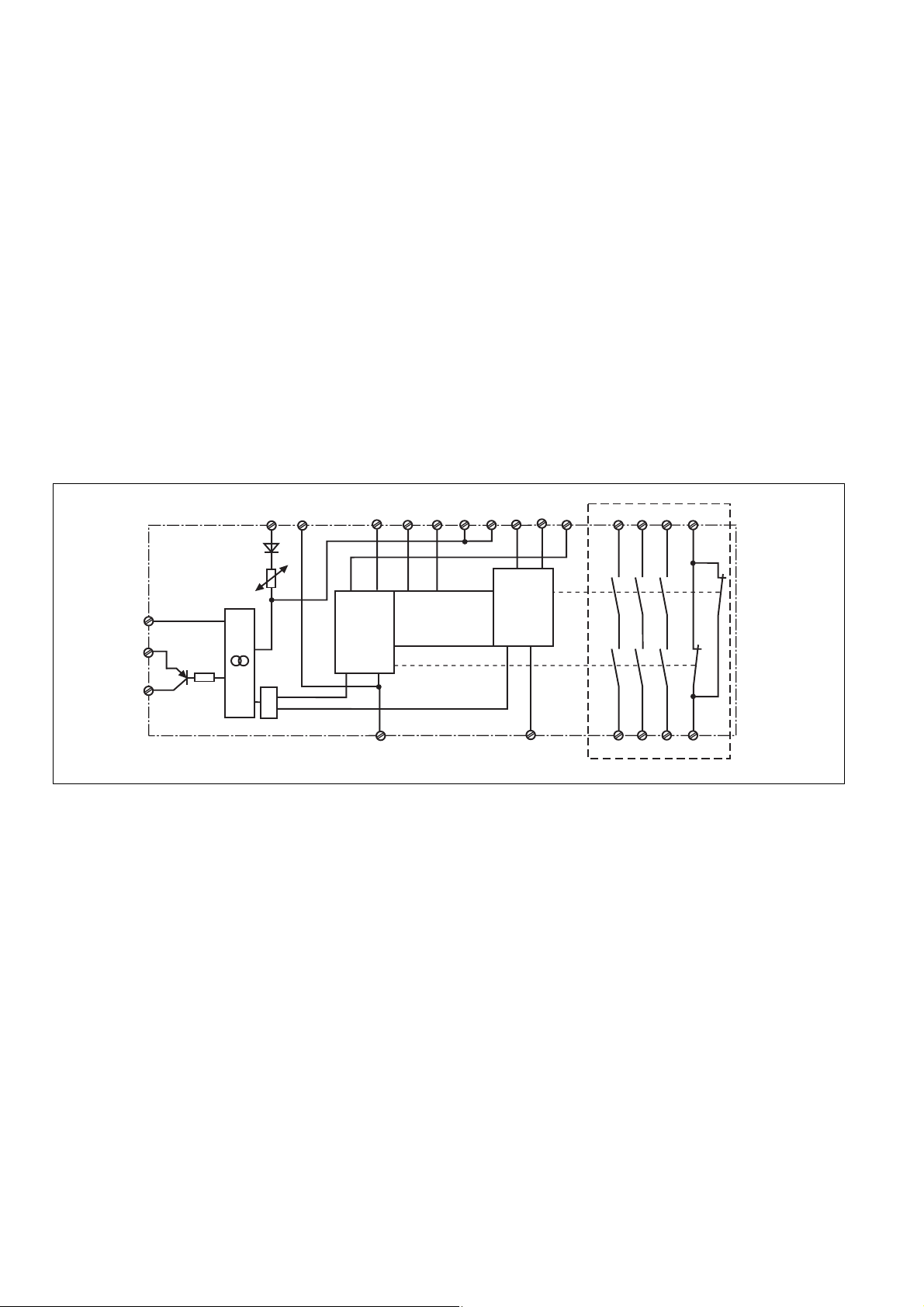
Y30
Y31
Y32
A1 A2 S13S14 S12
&
S34 41
S33
CH2
S21
Fig. 1: Innenschaltbild/Internal Wiring Diagram/Schéma de principe
* Isolation zum nicht markierten Bereich und der
Relaiskontakte zueinander: Basisisolierung
(Überspannungskategorie III), sichere Trennung
(Überspannungskategorie II)
Betriebsarten:
• Einkanaliger Betrieb: Eingangsbeschaltung
nach VDE 0113-1 und EN 60204-1, keine
Redundanz im Eingangskreis, Erdschlüsse
im Tasterkreis werden erkannt.
• Zweikanaliger Betrieb: Redundanter Eingangskreis, Erdschlüsse im Tasterkreis und
Querschlüsse zwischen den Tasterkontakten
werden erkannt.
• Automatischer Start: Gerät ist aktiv, sobald
der Eingangskreis geschlossen ist.
• Manueller Start mit Überwachung: Gerät ist
nur aktiv, wenn vor dem Schließen des
Eingangskreises der Startkreis geöffnet wird
und der Startkreis nach dem Schließen des
Eingangskreises und nach Ablauf der
Wartezeit (s. techn. Daten) geschlossen
wird.
• Kontaktvervielfachung und -verstärkung
durch Anschluss von externen Schützen
* Insulation between the non-marked area
and the relay contacts: Basic insulation
(overvoltage category III), safe separation
(overvoltage category II)
Operating Modes
• Single-channel operation: Input wiring
according to VDE 0113-1 and
EN 60204-1, no redundancy in the input
circuit. Earth faults are detected in the
emergency stop circuit.
• Two-channel operation: Redundancy in the
input circuit. Earth faults in the Emergency
Stop circuit and shorts across the
emergency stop push button are also
detected.
• Automatic reset: Unit is active as soon as
the input circuit is closed.
• Manual reset with monitoring: Unit will only
be active if the reset circuit is opened before
the input circuit closes, and the reset circuit
is closed after the input circuit has closed
and the waiting time has elapsed (see
technical data).
• Increase in the number of available contacts
by connection of external contactors/relays.
Start
Unit
S11
CH1
S22
S32S31
K1
K2
14
13
24
23
33
34
*
42
* Isolation de la partie non sélectionnée par
rapport aux contacts relais : isolation basique
(catégorie de surtensions III), isolation
galvanique (catégorie de surtensions II)
Modes de fonctionnement
• Commande par 1 canal : conforme aux
prescriptions de la EN 60204/1, pas de
redondance dans le circuit d’entrée. La mise
à la terre du circuit d’entrée est détectée
• Commande par 2 canaux: circuit d’entrée
redondant. La mise à la terre et les courtscircuits entre les contacts sont détectés.
• Réarmement automatique : le relais est
activé dès la fermeture des canaux d’entrée.
• Réarmement manuel auto-contrôlé:
lL'appareil est uniquement actif lorsque le
circuit de réarmement est ouvert avant
fermeture des circuits d'entrées et que le
circuit de réarmement est fermé après
fermeture des circuits d'entrées et
écoulement du temps d'attente (voir les
caractéristiques techniques).
• Augmentation du nombre de contacts ou du
pouvoir de coupure par l’utilisation de
contacteurs externes.
- 2 -

Montage
Das Sicherheitsschaltgerät muss in einen
Schaltschrank mit einer Schutzart von mind.
IP54 eingebaut werden. Zur Befestigung auf
einer Normschiene dient ein Rastelement auf
der Rückseite des Geräts.
Installation
The safety relay must be panel mounted (min.
IP54). There is a notch on the rear of the unit
for DIN-Rail attachment.
Montage
Le relais doit être monté en armoire ayant un
indice de protection mini IP54. Sa face arrière
permet un montage sur rail DIN.
Inbetriebnahme
Beachten Sie bei der Inbetriebnahme
• Auslieferungszustand
Schraubklemmen: Brücke zwischen S11-
S12 (Eingangskreis zweikanalig)
• Nur die Ausgangskontakte 13-14/23-24/3334 sind Sicherheitskontakte. Ausgangskontakt 41-42 ist ein Hilfskontakt
(z. B. für Anzeige).
• Vor die Ausgangskontakte eine Siche-
rung (s. techn. Daten) schalten, um das
Verschweißen der Kontakte zu verhindern.
• Berechnung der max. Leitungslänge I
R
lmax
=
I
max
Rl / km
R
= max. Gesamtleitungs-
lmax
widerstand (s. technische Daten)
/km = Leitungswiderstand/km
R
l
Da die Funktion Querschlusserkennung
nicht einfehlersicher ist, wird sie von Pilz
während der Endkontrolle geprüft. Eine
Überprüfung nach der Installation des
Geräts ist wie folgt möglich:
1. Gerät betriebsbereit (Ausgangskontakte
geschlossen)
2. Die Testklemmen S22-S32 zur
Querschlussprüfung kurzschließen.
3. Die Sicherung im Gerät muss auslösen
und die Ausgangskontakte öffnen. Leitungslängen in der Größenordnung der Maximallänge können das Auslösen der Sicherung
um bis zu 2 Minuten verzögern.
4. Sicherung wieder zurücksetzen: den
Kurzschluss entfernen und die Betriebsspannung für ca. 1 Minute abschalten.
• Das Netzteil muss den Vorschriften für
Funktionskleinspannungen mit sicherer
elektrischer Trennung (SELV, PELV) nach
VDE 0100, Teil 410 entsprechen.
• Leitungsmaterial aus Kupferdraht mit einer
Temperaturbeständigkeit von 60/75 °C
verwenden.
• Sorgen Sie beim Anschluss von magnetisch
wirkenden, auf Reedkontakten basierenden
Näherungsschaltern dafür, dass der max.
Einschaltspitzenstrom (am Eingangskreis) den
Näherungsschalter nicht überlastet.
• Angaben im Kapitel „Technische Daten“
unbedingt einhalten.
Ablauf:
• Versorgungsspannung:
Versorgungsspannung an Klemmen A1 und
A2 anlegen.
• Startkreis:
- Automatischer Start: S13-S14 brücken.
- Manueller Start mit Überwachung: Taster
an S33-S34 anschließen (S13-S14
offen).
• Eingangskreis:
- Einkanalig: S21-S22 und S31-S32
brücken. Öffnerkontakt von Auslöseelement an S11 und S12 anschließen.
- Zweikanalig ohne Querschluss-
erkennung: S21-S22 brücken. Öffnerkontakt von Auslöseelement an S11-S12
und S11-S32 anschließen.
- Zweikanalig mit Querschlusserkennung:
S11-S12 brücken. Öffnerkontakt von
Auslöseelement an S21-S22 und S31S32 anschließen.
bei Geräten mit
max
:
Operation
Please note for operation:
equipped with screw terminals is
• Unit
delivered with a bridge between S11-S12
(2-channel input circuit)
• Only the output contacts 13-14/23-24/33-34
are safety contacts. Output contact 41-42 is
an auxiliary contact (e.g. for a display).
• To prevent a welding together of the
contacts, a fuse (see technical detail)
must be connected before the output
contacts.
• Calculate the max. Cable runs I
R
I
max
R
Technical details)
R
lmax
=
Rl / km
= max. overall cable resistance (see
lmax
/km = Cable resistance/km
l
As the function for detecting shorts across
the inputs is not failsafe, it is tested by Pilz
during the final control check. However, a
test is possible after installing the unit and it
can be carried out as follows:
1. Unit ready for operation (output contacts
closed)
2. Short circuit the test (connection)
terminals S22-S32 for detecting shorts
across the inputs.
3. The unit‘s fuse must be triggered and the
output contacts must open. Cable lengths in
the scale of the maximum length can delay
the fuse triggering for up to 2 minutes.
4. Reset the fuse: remove the short circuit
and switch off the operating voltage for
approx. 1 minute.
• The power supply must comply with the
regulations for extra low voltages with safe
electrical separation (SELV, PELV) in
accordance with VDE 0100, Part 410.
• Use copper wiring that will withstand
60/75 °C.
• When connecting magnetically operated,
reed proximity switches, ensure that the
max. peak inrush current (on the input
circuit) does not overload the proximity
switch.
• Important details in the section "Technical
Data“ should be noted and adhered to.
To operate:
• Supply operating voltage
Connect the operating voltage to terminals
A1 and A2.
• Reset circuit:
- Automatic reset: Bridge S13-S14.
- Manual reset with monitoring: Connect
button to S33-S34 (S13-S14 open).
• Input circuit:
- Single-channel: Bridge S21-S22 and
S31-S32. Connect N/C contact from
safety switch (e.g. Emergency-Stop) to
S12 and S11.
- Dual-channel, without short circuit
detection: Link S21-S22. Connect N/C
contact from safety switch
(e.g. emergency stop) to S11-S12 and
S11-S32
- Dual-channel, with short circuit detection:
Bridge S11-S12. Connect N/C contact
from safety switch (e.g. emergency-stop)
to S21-S22 and S31-S32.
- 3 -
max
:
Mise en oeuvre
Remarques préliminaires :
• Pontages présents à la livraison
avec bornes à vis : S11-S12 (commande
par 2 canaux)
• Seuls les contacts 13-14, 23-24, 33-34 sont
des contacts de sécurité. Le contact 41-42
est un contact d’information (ex. voyant)
• Raccordez une fusible (voir les
caractéristiques techniques) avant les
contacts de sortie afin d'éliminer tout
risque de fusion.
• Calculer les longueurs de câblage max I
dans le circuit d’entrée:
R
lmax
=
I
max
Rl / km
R
= Résistivité de câblage totale max.
lmax
(voir les caractéristiques techniques)
/km = résistivité de câblage/km
R
l
La fonction de détection de court-circuit est
testé par Pilz lors du contrôle final. Un test
sur site est possible de la façon suivante :
1. Appareil en fonction (contacts de sortie
fermés)
2. Court-circuiter les bornes de
raccordement nécessaires au test S22-S32.
3. Le fusible interne du relais doit
déclencher et les contacts de sortie doivent
s‘ouvrir. Le temps de réponse du fuisible
peut aller jusqu‘à 2 min. si les longueurs de
câblage sont proches des valeurs maximales.
4. Réarmement du fusible : enlever le courtcircuit et couper l‘alimentation du relais
pendant au moins 1 min.
• L'alimentation doit satisfaire aux
prescriptions relatives aux tensions extra
basses avec une isolation électrique de
sécurité (SELV, PELV) selon VDE 0100,
partie 410.
• Utiliser uniquement des fils de cablâge en
cuivre 60/75 °C.
• Lors du raccordement de détecteurs de
proximité magnétiques, basés sur des
contacts Reed, veuillez vous assurer que le
courant de crête max. à la mise sous
tension (sur le circuit d'entrée) ne surcharge
pas les détecteurs de proximité.
• Respecter les données indiquées dans le
chap. „Caractéristiques techniques“.
Mise en oeuvre :
• Tension d’alimentation
amener la tension d’alimentation sur A1 et
A2.
• Circuit de réarmement:
- réarmement automatique: pontage des
bornes S13-S14
- réarmement manuel auto-côntrolé:
câblage d'un poussoir sur S33-S34
(S13-S14 ouvert).
• Circuits d’entrée:
- Commande par 1 canal : câblage du
contact à ouverture entre S11-S12,
pontage entre S21-S22 et S31-S32
- Commande par 2 canaux sans détection
des courts-circuits: câblage des contacts
à ouverture entre S11-S12, S11-S32,
pontage entre S21-S22
- Commande par 2 canaux
des courts-circuits: câblage des contacts
à ouverture entre S21-S22 et S31-S32,
pontage entre S11-S12
au appareil
max
avec détection
•
Rückführkreis:
Externe Schütze in Reihe zu Startkreis S13S14 bzw. S33-S34 anschließen.
• 24 V Versorgungsspannung für Halbleiterausgang: +24 V DC an Klemme Y31 und
0 V an Klemme Y30 anschließen.
Die Sicherheitskontakte sind aktiviert (geschlossen) und der Hilfskontakt 41-42 ist geöffnet. Die Statusanzeige für "CH.1",
"CH. 2", leuchten. Das Gerät ist betriebsbereit. Wird der Eingangskreis geöffnet, öffnen
die Sicherheitskontakte 13-14/23-24/33-34
und der Hilfskontakt 41-42 schließt. Die
Statusanzeige erlischt.
Wieder aktivieren
• Eingangskreis schließen.
• Bei manuellem Start mit Überwachung
Taster zwischen S33 und S34 betätigen.
Die Statusanzeigen leuchten wieder, die
Sicherheitskontakte sind geschlossen.
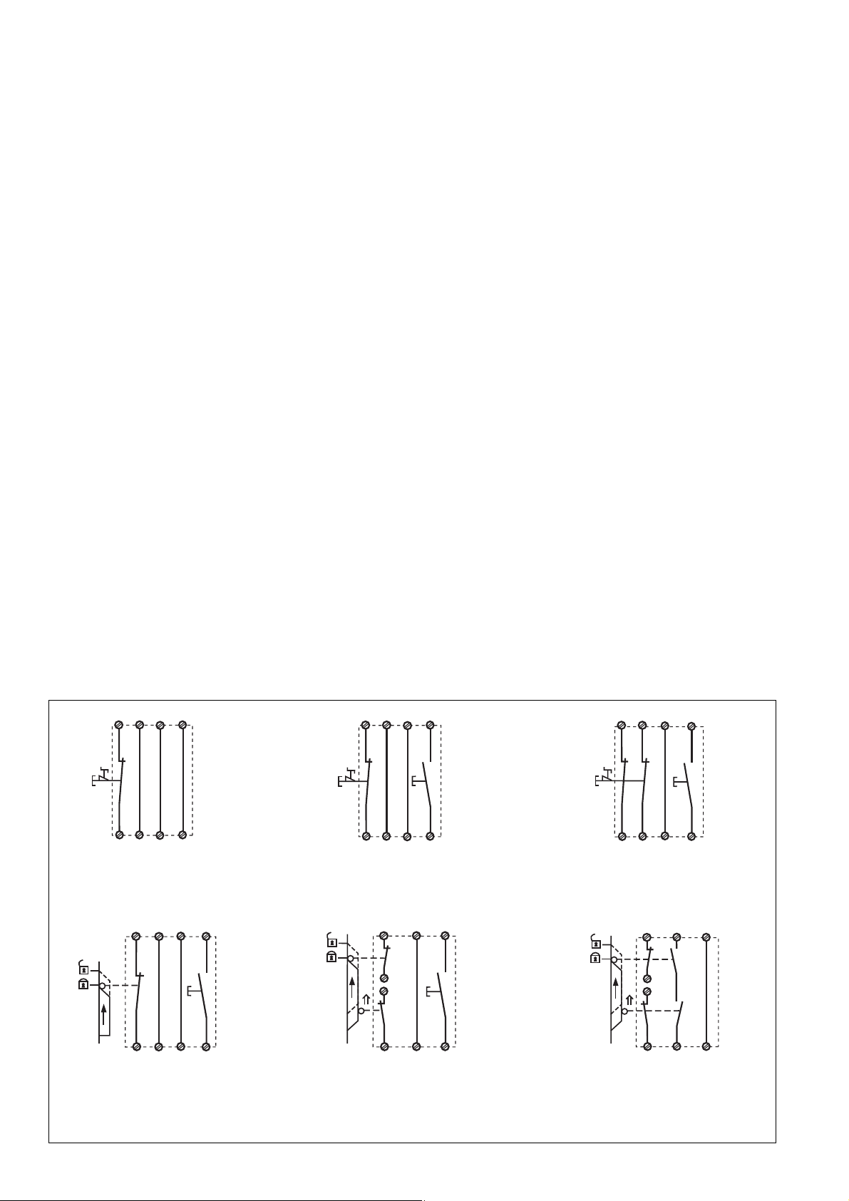
Anwendung
In Fig. 2 ... Fig. 10 sind Anschlussbeispiele
für Not-Halt-Beschaltung mit automatischem
und überwachtem Start, Schutztüransteuerungen sowie Kontaktvervielfachung
durch externe Schütze.
Bitte beachten Sie:
• Fig. 2 und 7: keine Verbindung S33-S34
• Fig. 3, 4, 5, 6, 8:
keine Verbindung S13-S14
• Fig. 7: Automatischer Start bei Schutztürsteuerung: Das Gerät ist bei geöffneter
Schutztür über den Startkreis S13-S14 startbereit. Nach Schließen der Eingangskreise
S21-S22 und S31-S32 werden die
Sicherheitskontakte geschlossen.
Beachten Sie bei Fig. 2 und 7: Das Gerät
startet bei Spannungsausfall und -wiederkehr
automatisch. Verhindern Sie einen unerwarteten Wiederanlauf durch externe
Schaltungsmaßnahmen.
• Feedback control loop:
Connect external relays/contactors in series
to reset circuit S13-S14 or S33-S34.
• 24 VDC supply voltage for semi-conductor
output: Connect +24 VDC to terminals Y31
and 0 VDC to Y30.
The safety contacts are activated (closed) and
the auxiliary contact (41-42) is open. The
status indicators "CH.1"and "CH.2" are
illuminated. The unit is ready for operation. If
the input circuit is opened, the safety contacts
13-14/23-24, 33-34 open and the auxiliary
contact 41-42 closes. The status indicator
goes out.
Reactivation
• Close the input circuit.
• For manual reset with monitoring, press
the button between S33-S34.
The status indicators light up again, the
safety contacts are closed.
Application
In Fig. 2 ...Fig. 10 are connection examples
for Emergency Stop wiring with automatic
and monitored reset. Safety gate controls as
well as contact expansion via external
contactors.
• Fig. 2 and 7: S33-S34 not connected
• Fig. 3, 4, 5, 6, 8: S13-S14 not connected
• Fig. 7: Automatic reset with safety gate
control: with the safety gate open the unit
is ready for operation via reset circuit S13S14. After closing the safety input circuit
S21-S22 and S31-S32 the safety contacts
will close.
Please note for Fig. 2 and 7: the device starts
automatically after loss of power. You should
prevent an unintended start-up by using
external circuitry measures.
• Boucle de retour:
câbler les contacts des contacteurs
externes en série dans le circuit de
réarmement S13-S14 ou S33-S34.
• Alimentation en 24 VCC de sortie statique:
relier le +24 V DC à la borne Y31 et le 0 V à
la borne Y30.
Les contacts de sécurité se ferment et le
contact d’information 41-42 s’ouvre. Les LEDs
"CH.1"et "CH.2" sont allumées. L’appareil est
prêt à fonctionner.
Si le circuit d’entrée est ouvert, les contacts
de sécurité retombent et le contact
d’information 41-42 se ferme. Les LEDs
s’éteignent.
Remise en route :
• fermer le circuit d’entrée.
• en cas de surveillance du circuit de
réarmement, appuyer le poussoir de
validation S33-S34.
Les affichages d'état s'allument à nouveau.
Les contacts de sécurité sont fermées.
Utilisation
Les figures 2 à 10 représentent les
différents câblages possibles du PNOZ X3P
à savoir : poussoir AU avec réarmement
automatique ou auto-côntrolé, interrupteurs
de position et augmentation du nombre des
contacts de sécurité par contacteurs
externes.
• Fig. 2 et 7: pas de câblage sur S33-S34
• Fig. 3, 4, 5, 6, 8:
pas de câblage sur S13-S14
• Fig. 7: Réarmement automatique en cas
de surveillance protecteur: lorsque le
protecteur est ouvert, le circuit S13-S14
se ferme et le relais est prêt à
fonctionner. Dès la fermeture des canaux
d'entrée S21-S22 et S31-S32, les
contacts de sortie du relais se ferment.
Dans le cas de la figure 2 et 7, l’appareil se
réarme automatiquement après une
coupure et une remise sous tension. Evitez
tout risque de redémarrage par un câblage
externe approprié.
S11 S31
S21
S13
S1
S32
S12
S22
S14
Fig. 2: Eingangskreis einkanalig, automat.
Start/Single-channel input circuit, automatic
reset/Commande par 1 canal, validation
automatique
S11
S12
S21
S1
S22
S31
S32
S33
S3
S34
Fig. 5: Schutztürsteuerung einkanalig,
überwachter Start/Single-channel safety gate
control, monitored reset/Surveillance de
protecteur, commande par 1 canal,
surveillance du poussoir de validation
S11 S31
S1
S12
S32
S21
S22
S33
S3
S34
Fig. 3: Eingangskreis einkanalig, überwachter Start/Single-channel input circuit,
monitored reset/Commande par 1 canal,
surveillance du poussoir de validation
S33
S11
S21
S1
S22
S3
S31
S2
S32
S12
S34
Fig. 6: Schutztürsteuerung zweikanalig,
überwachter Start/Two-channel safety gate
control, monitored reset/Surveillance de
protecteur, commande par 2 canaux,
surveillance du poussoir de validation
S11
S12
S33
S3
S34
S1
S21
S22
S31
S32
Fig.4: Eingangskreis zweikanalig, überwachter Start/Two-channel input circuit, monitored
reset/Commande par 2 canaux, surveillance
du poussoir de validation
S13
S14
S11
S1
S2
S12
S21
S22
S31
S32
Fig. 7: Schutztürsteuerung zweikanalig,
automatischer Start/Two channel safety gate
control, automatic reset/Surveillance de
protecteur, commande par 2 canaux,
validation automatique
- 4 -

14
K5 K6
13
S33 S34
K5
K6
1L1
1L2
S3
BWS
S11
24 V DC
S3
S33S21S31
1L1
K6
K5
S13 S14
13
S12 S22 S34S32
Fig. 8: Lichtschrankensteuerung, zweikanalig, Querschlusserkennung durch BWS,
überwachter Start/Dual-channel light curtain
control, short circuit detection via ESPE,
monitored reset/Commande par 2 canaux
par barrage immatériel, surveillance du
poussoir de validation
SPS
+ 24V
E0.0
E0.1
E0.2
E0.3
A0.0
A0.1
A0.2
A0.3
0V
A2
Y30
Y31
Y32
14
24
34
42
PNOZ X3P
Fig. 11: Anschlussbeispiel für Halbleiterausgang/Connection of semiconductor output/
Câblage de la sortie statique
14
K5 K6
1L2
Fig. 9: Anschlussbeispiel für externe
Schütze, einkanalig, automatischer Start/
Connection example for external contactors/
relays, single-channel, automatic reset/
Fig. 10: wie Fig. 9 mit überwachtem Start/
Like Fig. 9 with monitored reset/comme Fig.
9 avec surveillance du poussoir de
validation
Branchement contacteurs externes,
commande par 1 canal, validation
automatique
betätigtes Element/Switch
activated/élément actionné
Tür nicht geschlossen/Gate open/
porte ouverte
Tür geschlossen/Gate closed/
porte fermée
S1/S2: Not-Halt- bzw. Schutztürschalter/Emergency Stop Button, Safety Gate Limit Switch/
Poussoir AU, détecteurs de position
S3: Starttaster/Reset button/Poussoir de réarmement
Fehler - Störungen
• Erdschluss bei PNOZ X3P:
Eine elektronische Sicherung bewirkt das
Öffnen der Ausgangskontakte. Nach
Wegfall der Störungsursache und
Abschalten der Versorgungsspannung für
ca. 1 min ist das Gerät wieder betriebsbereit.
• Fehlfunktionen der Kontakte: Bei verschweißten Kontakten ist nach Öffnen des
Eingangskreises keine neue Aktivierung
möglich.
• LED "Power" leuchtet nicht: Kurzschluss
oder Versorgungsspannung fehlt.
Technische Daten
Elektrische Daten
Versorgungsspannung U
Spannungstoleranz
Leistungsaufnahme bei U
Frequenzbereich
Restwelligkeit
Spannung und Strom an
Eingangskreis
Startkreis
Rückführkreis
Anzahl der Ausgangskontakte
Sicherheitskontakte (S)
Hilfskontakte (Ö)
B
B
Technical Data
Electrical data
Supply Voltage U
Voltage Tolerance
Power consumption at U
Frequency Range
Residual Ripple
Voltage and Current at
Input circuit
Reset circuit
Feedback loop
Number of output contacts
Safety contacts (N/O)
Auxilliary contacts (N/C)
Faults
• Earth fault on PNOZ X3P:
An electronic fuse causes the output
contacts to open. Once the cause of the
fault has been removed and operating
voltage is switched off for approx. 1
minute, the unit will be ready for operation.
• Contact failure: In the case of welded
contacts, no further activation is possible
following an opening of the input circuit.
• LED "Power" is not illuminated if shortcircuit or the supply voltage is lost.
Caractéristiques techniques
Données électriques
B
B
Tension d’alimentation U
Plage de la tension d’alimentation
Consommation pour U
Fréquence
Ondulation résiduelle
Tension et courant du
Circuit d’entrée
Circuit de réarmement
Boucle de retour
Nombre de contacts de sortie
contacts de sécurité (F)
contact d'info (O)
Erreurs - Défaillances
• Défaut de masse du PNOZ X3P:
un fusible électronique entraîne l’ouverture
des contacts de sortie. Une fois la cause
du défaut éliminée et la tension
d’alimentation coupée pour environ 1
minute, l’appareil est à nouveau prêt à
fonctionner.
• Défaut de fonctionnement des contacts de
sortie: en cas de soudage d’un contact lors
de l’ouverture du circuit d’entrée, un
nouvel réarmement est impossible.
• LED "Power" éteinte: tension
d'alimentation non présente ou courtcircuit interne.
B
B
24 V AC/DC
-15 ... +10 %
UB = 24 V DC: 2,5 W
UB = 24 V AC: 5,0 VA
50 ... 60 Hz
DC: 160 %
UB = 24 V DC: 40 mA
UB = 24 V DC: 70 mA
UB = 24 V DC: 20 mA
3
1
- 5 -

Gebrauchskategorie nach
EN 60947-4-1
EN 60947-5-1(DC13:
6 Schaltspiele/Min.)
Kontaktmaterial
Kontaktabsicherung extern
EN 60947-5-1 (IK = 1 kA)
Schmelzsicherung flink
Schmelzsicherung träge
Sicherungsautomat
Charakteristik
Halbleiterausgänge (kurzschluss-
fest)
Externe Spannungsversorgung
Spannungstoleranz
Max. Gesamtleitungswiderstand R
Eingangskreise
einkanalig DC
einkanalig AC
zweikanalig mit
Querschlusserkennung DC
zweikanalig mit
Querschlusserkennung AC
zweikanalig ohne
Querschlusserkennung DC
zweikanalig ohne
Querschlusserkennung AC
Min. Eingangswiderstand im
Einschaltmoment
Sicherheitstechnische Kenndaten
der Sicherheitsausgänge
PL nach EN ISO 13849-1: 2006
Kategorie nach EN 954-1
SIL CL nach EN IEC 62061
PFH nach EN IEC 62061
SIL nach IEC 61511
PFD nach IEC 61511
TM [Jahr] nach EN ISO 13849-1: 2006
Zeiten
Einschaltverzögerung
Automatischer Start
Automatischer Start nach Netz-Ein
Überwachter Start
Rückfallverzögerung
bei Not-Halt
bei Netzausfall
Wiederbereitschaftszeit bei max.
Schaltfrequenz 1/s
nach Not-Halt
nach Netzausfall
Gleichzeitigkeit Kanal 1 und 2
Wartezeit bei überwachtem Start
Min. Startimpulsdauer bei
überwachtem Start
Überbrückung bei
Spannungseinbrüchen
Umweltdaten
EMV
Schwingungen nach EN 60068-2-6
Frequenz
Amplitude
Klimabeanspruchung
Utilization category in accordance with
EN 60947-4-1
EN 60947-5-1(DC13: 6 cycles/min)
Contact material
External contact fuse protection
EN 60947-5-1 (IK = 1 kA)
Blow-out fuse quick
Blow-out fuse slow
Safety cut-out
Cvaracteristic
semiconductor outputs (short
circuit-proof)
External supply voltage
Voltage Tolerance
Max. overall cable resistance R
lmax
input circuits
Single-channel DC
Single-channel AC
Dual-channel with detection of
shorts across contacts DC
Dual-channel with detection of
shorts across contacts AC
Dual-channel without detection of
shorts across contacts DC
Dual-channel without detection of
shorts across contacts AC
Min. input resistance when
switching on
Safety-related characteristics of
the safety outputs
PL in accordance with
EN ISO 13849-1: 2006
Category in accordance with
EN 954-1
SIL CL in accordance with
EN IEC 62061
PFH in accordance with
EN IEC 62061
SIL in accordance with IEC 61511
PFD in accordance with IEC 61511
TM [year] in accordance with
EN ISO 13849-1: 2006
Times
Switch-on delay
Automatic reset
Automatic reset after Power-ON
Monitored manual reset
Delay-on De-Energisation
at E-STOP
with power failure
Recovery time at max. switching
frequency 1/s
after E-STOP
after power failure
Simultaneity channel 1 and 2
Waiting period on monitored reset
Min. start pulse duration with a
monitored reset
Supply interruption before deenergisation
Environmental data
EMC
Vibration to EN 60068-2-6
Frequency
Amplitude
Climate Suitability
Catégorie d’utilisation selon
EN 60947-4-1
EN 60947-5-1(DC13:
6 manoeuvres/min)
Matériau contact
Protection des contacts externe
EN 60947-5-1 (IK = 1 kA)
Fusibles rapide
Fusibles normal
Dijoncteur
Caractéristique
sorties statiques (protegées
contre c.c.)
Tension d'alimentation externe
Plage de la tension
Résistance de câblage totale max.
lmax
R
circuits d'entrée
lmax
Commande par 1 canal DC
Commande par 1 canal AC
Commande par 2 canaux avec
détection des court-circuits DC
Commande par 2 canaux avec
détection des court-circuits AC
Commande par 2 canaux sans
détection des court-circuits DC
Commande par 2 canaux sans
détection des court-circuits AC
Résistance d'entrée min. au moment
de la mise en marche
Caractéristiques techniques de
sécurité des sorties de sécurité
PL selon EN ISO 13849-1: 2006
Catégorie selon EN 954-1
SIL CL selon EN IEC 62061
PFH selon EN IEC 62061
SIL selon IEC 61511
PFD selon IEC 61511
TM [année] selon EN ISO 13849-1:
2006
Temporisations
Temps de réarmement
Réarmement automatique
Réarmement automatique après
mise sous tension
Réarmement manuel auto-contrôlé
Temps de retombée
en cas d'arrêt d'urgence
en cas de coupure d'alimentation
Temps de remise en service en cas de
fréquence de commutation max. 1/s
arrêt d'urgence
après une coupure d'alimentation
Désynchronisme canal 1 et 2
Temps d’attente en cas d’un
démarrage surveillé
Durée minimale de l'impulsion pour
un réarmement auto-contrôlé
Tenue aux micro-coupures
Données sur l'environnement
CEM
Vibrations selon EN 60068-2-6
Frequence
Amplitude
Conditions climatiques
AC1: 240 V/0,01 ... 8 A/
2000 VA
DC1: 24 V/0,01 ... 8 A/
200 W
AC15: 230 V/5 A;
DC13: 24 V/6 A
AgSnO2+ 0,2 µm Au
10 A
6 A
24 V AC/DC: 6 A
B/C
24 V DC, 20 mA
24 V DC
-20 % / +20 %
150 Ohm
180 Ohm
15 Ohm
30 Ohm
300 Ohm
360 Ohm
90 Ohm
PL e (Cat. 4)
Cat. 4
SIL CL 3
2,31E-09
SIL 3
2,03E-06
20
typ. 250 ms, max. 500 ms
typ. 280 ms, max. 550 ms
typ. 35 ms, max. 50 ms
typ. 15 ms, max. 30 ms
typ. 50 ms, max. 70 ms
50 ms
100 ms
∞
300 ms
30 ms
20 ms
EN 60947-5-1,
EN 61000-6-2,
EN 61000-6-3
10 ... 55 Hz
0,35 mm
EN 60068-2-78
- 6 -

Luft- und Kriechstrecken nach
EN 60947-1
Verschmutzungsgrad
Überspannungskategorie
Bemessungsisolationsspannung
Bemessungsstoßspannungs-
festigkeit
Umgebungstemperatur
Lagertemperatur
Schutzart
Einbauraum (z. B. Schaltschrank)
Gehäuse
Klemmenbereich
Mechanische Daten
Gehäusematerial
Gehäuse
Front
Querschnitt des Außenleiters
(Schraubklemmen)
1 Leiter, flexibel
2 Leiter gleichen Querschnitts, flexi-
bel mit Aderendhülse, ohne
Kunststoffhülse
ohne Aderendhülse oder mit TWIN-
Aderendhülse
Querschnitt des Außenleiters
(Federkraftklemmen)
flexibel ohne Aderendhülse
Gehäuse mit Federkraftklemmen
Abisolierlänge
Klemmstellen pro Anschluss
Anzugsdrehmoment für
Schraubklemmen
Abmessungen (Schraubklemmen)
H x B x T
Abmessungen (Federkraftklemmen)
H x B x T
Einbaulage
Gewicht
Airgap Creepage in accordance with
EN 60947-1
Pollution degree
Overvoltage category
Rated insulation voltage
Rated impulse withstand voltage
Ambient temperature
Storage temperature
Protection type
Mounting (eg. panel)
Housing
Terminals
Mechanical data
Housing material
Housing
Front panel
Cable cross section (screw
terminals)
1 core, flexible
2 core, same cross section flexible
with crimp connectors, without
insulating sleeve
without crimp connectors or with
TWIN crimp connectors
Cable cross section (spring-loaded
terminals)
flexible without crimp connectors
Housing with spring-loaded terminals
Stripping length
Termination points per connection
Torque setting for screw terminals
Dimensions (screw terminals)
H x W x D
Dimensions (spring-loaded terminals)
H x W x D
Fitting Position
Weight
Cheminement et claquage selon
EN 60947-1
Niveau d'encrassement
Catégorie de surtensions
Tension assignée d'isolement
Tension assignée de tenue aux
chocs
Température d’utilisation
Température de stockage
Indice de protection
Lieu d'implantation (ex. armoire)
Boîtier
Bornes
Données mécaniques
Matériau du boîtier
Boîtier
Face avant
Capacité de raccordement
(borniers à vis)
1 conducteur souple
2 conducteurs de même diamètre
souple avec embout, sans chapeau
plastique
souple sans embout ou avec
embout TWIN
Capacité de raccordement (borniers
à ressort)
souple sans embout
Boîtier avec borniers à ressort
Longueur de dénudage
Bornes par raccordement
Couple de serrage (borniers à vis)
Dimensions (borniers à vis)
H x P x L
Dimensions (borniers à ressort)
H x L x P
Position de travail
Poids
2
III / II
250 V
4 kV
-20 ... + 55 °C
-40 ... +85 °C
IP54
IP40
IP20
PPO UL 94 V0
ABS UL 94 V0
0,25 ... 2,5 mm2, 24 - 12 AWG
0,25 ... 1 mm2, 24 - 16 AWG
0,20 ... 1,5 mm2, 24 - 16 AWG
0,20 ... 1,5 mm2, 24 - 16 AWG
8 mm
2
0,5 Nm
94 x 45 x 121 mm
101 x 45 x 121 mm
beliebig/any/indifférente
270 g
ACHTUNG!
Beachten Sie unbedingt die
Lebensdauerkurve der Relais. Die
sicherheitstechnischen Kennzahlen
der Relaisausgänge gelten nur,
solange die Werte der Lebensdauer-
kurven eingehalten werden.
Der PFH-Wert ist abhängig von der Schaltfrequenz und der Belastung des Relaisausganges. Solange die Lebensdauerkurven
nicht erreicht werden, kann der angegebene
PFH-Wert unabhängig von der Schaltfrequenz und der Belastung verwendet
werden, da der PFH-Wert den B10d-Wert der
Relais sowie die Ausfallraten der anderen
Bauteile bereits berücksichtigt.
Alle in einer Sicherheitsfunktion verwendeten
Einheiten müssen bei der Berechnung der
Sicherheitskennwerte berücksichtigt werden.
INFO
Die SIL-/PL-Werte einer Sicherheitsfunktion sind nicht identisch mit den
SIL-/PL-Werten der verwendeten
Geräte und können von diesen
abweichen. Wir empfehlen zur
Berechnung der
SIL-/PL-Werte der Sicherheitsfunktion
das Software-Tool PAScal.
Es gelten die 2009-11 aktuellen Ausgaben
der Normen.
CAUTION!
It is essential to consider the relay’s
service life graphs. The relay outputs’
safety-related characteristic data is
only valid if the values in the service
life graphs are met.
The PFH value depends on the switching
frequency and the load on the relay output.
If the service life graphs are not accessible,
the stated PFH value can be used
irrespective of the switching frequency and
the load, as the PFH value already considers
the relay’s B10d value as well as the failure
rates of the other components.
All the units used within a safety function
must be considered when calculating the
safety characteristic data.
INFORMATION
A safety function’s SIL/PL values are
not identical to the SIL/PL values of
the units that are used and may be
different. We recommend that you
use the PAScal software tool to
calculate the safety function’s SIL/PL
values.
The version of the standards current at
2009-11 shall apply.
ATTENTION!
Veuillez absolument tenir compte des
courbes de durée de vie des relais. Les
caractéristiques de sécurité des sorties
relais sont uniquement valables tant que
les valeurs des courbes de durée de vie
sont respectées.
La valeur PFH dépend de la fréquence de
commutation et de la charge de la sortie
relais.
Tant que les courbes de durée de vie ne sont
pas atteintes, la valeur PFH indiquée peut
être utilisée indépendamment de la
fréquence de commutation et de la charge
car la valeur PFH prend déjà en compte la
valeur B10d des relais ainsi que les taux de
défaillance des autres composants.
Toutes les unités utilisées dans une fonction
de sécurité doivent être prises en compte
dans le calcul des caractéristiques de
sécurité.
INFORMATION
Les valeurs SIL / PL d’une fonction de
sécurité ne sont identiques aux
valeurs SIL / PL des appareils utilisés
et peuvent varier par rapport à celles-
ci. Pour le calcul des valeurs SIL / PL
de la fonction de sécurité, nous
recommandons l’outil logiciel PAScal.
Se référer à la version des normes en vigeur
au 2009-11.
- 7 -

Konventioneller thermischer Strom bei gleichzeitiger Belastung mehrerer Kontakte/Conventional thermal
current while loading several contacts/Courant thermique conventionnel en cas de charge sur plusieurs
contacts (AC1, DC1)
Anzahl der Kontakte/number of contacts/nombre des contacts 3 2 1
Ith (A) bei UB AC/at UB AC/pour UB AC 6,0 7,0 8,0
Ith (A) bei UB DC/at UB DC/pour UB DC 7,0 8,0 8,0
Bestelldaten/Order reference/Caractéristiques
Typ/
Type/
Type
PNOZ X3P C
PNOZ X3P
Merkmale/
Features/
Caractéristiques
24 V AC/DC
24 V AC/DC
Klemmen/
Terminals/
Borniers
Federkraftklemmen/spring-loaded terminals/
borniers à ressort
Schraubklemmen/screw terminals/borniers à vis
Bestell-Nr./
Order no./
Référence
787 310
777 310
- 8 -

Lebensdauerkurve
Die Lebensdauerkurven geben an, ab
welcher Schaltspielzahl mit verschleißbedingten Ausfällen gerechnet werden muss.
Der Verschleiß wird vor allem durch die
elektrische Belastung verursacht, der
mechanische Verschleiß ist
vernachlässigbar.
Service life graph
The service life graphs indicate the number
of cycles from which failures due to wear
must be expected. The wear is mainly
caused by the electrical load; the mechanical
load is negligible.
Courbe de durée de vie
Les courbes de durée de vie indiquent à
partir de quel nombre de manoeuvres il faut
s’attendre à des défaillances liées à l’usure.
La charge électrique est la cause principale
de l’usure, l’usure mécanique étant
négligeable.
Beispiel:
Induktive Last: 0,2 A
Gebrauchskategorie: AC15
Lebensdauer der Kontakte: 4 000 000
Schaltspiele
Solange die zu realisierende Applikation nur
eine Schaltspielzahl von weniger als
4 000 000 Schaltspielen erfordert, kann mit
dem PFH-Wert (s. technische Daten)
gerechnet werden.
Um die Lebensdauer zu erhöhen, an allen
Ausgangskontakten für eine ausreichende
Funkenlöschung sorgen. Bei kapazitiven
Lasten sind eventuell auftretende Stromspitzen zu beachten. Bei DC-Schützen
Freilaufdioden zur Funkenlöschung einsetzen.
Example:
Inductive load: 0,2 A
Utilisation category: AC15
Contact service life: 4 000 000 cycles
Provided the application requires fewer than
4 000 000 cycles, the PFH value (see
technical details) can be used in the
calculation.
To increase the service life, sufficient spark
suppression must be provided on all output
contacts. With capacitive loads, any power
surges that occur must be noted. With
contactors, use freewheel diodes for spark
suppression.
Exemple:
Charge inductive : 0,2 A
Catégorie d’utilisation : AC15
Durée de vie des contacts : 4 000 000
manoeuvres
Tant que l’application à réaliser requière un
nombre de manoeuvres inférieur à
4 000 000, on peut se fier à la valeur PFH
(voir les caractéristiques techniques).
Assurez-vous qu’il y ait une extinction d’arc
suffisante sur tous les contacts de sortie afin
d’augmenter la durée de vie. Faites attention
à l’apparition de pointes de courant en cas
de charges capacitatives. En cas de
contacteurs DC, utilisez des diodes de roue
libre pour l’extinction des étincelles. .
- 9 -
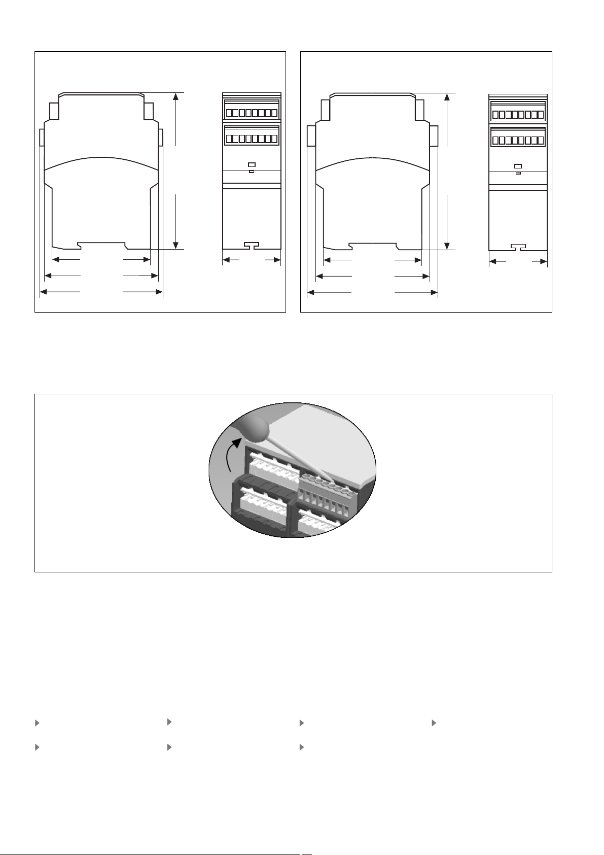
Abmessungen in mm (")/Dimensions in mm (")/Dimensions en mm (")
Gehäuse mit steckbaren Schraubklemmen/
Housing with plug-in screw terminals/
Boîtier avec borniers débrochables à vis
75 (2.95")
87 (3.42")
94 (3.70")
Steckbare Klemmen abziehen
Schraubendreher in Gehäuseaussparung
hinter der Klemme ansetzen und Klemme
heraushebeln.
Klemmen nicht an den Kabeln abziehen!
121 (4.76")
Remove plug-in terminals
Insert screwdriver into the cut-out of the
housing behind the terminal and lever the
terminal.
Do not remove the terminals by pulling the
cables!
45
(1.77")
Gehäuse mit steckbaren Federkraftklemmen/
Housing with plug-in spring-loaded terminals/
Boîtier avec borniers débrochables à ressort/
121 (4.76")
75 (2.95")
87 (3.42")
101 (3.98")
Démonter les borniers
débrochables
Placer un tournevis derrière les bornes et
sortir le bornier.
Ne pas retirer les borniers en tirant sur les
câbles !
45
(1.77")
Abziehen der Klemmen am Beispiel einer
Schraubklemme
EG-Konformitätserklärung:
Diese(s) Produkt(e) erfüllen die Anforderungen der Richtlinie 2006/42/EG über Maschinen des europäischen Parlaments und des
Rates.
Die vollständige EG-Konformitätserklärung
finden Sie im Internet unter www.pilz.com
Bevollmächtigter: Norbert Fröhlich,
Pilz GmbH & Co. KG, Felix-Wankel-Str. 2,
73760 Ostfildern, Deutschland
Technischer Support
+49 711 3409-444 +49 711 3409-444
...
In vielen Ländern sind wir durch
unsere Tochtergesellschaften und
Handelspartner vertreten.
Nähere Informationen entnehmen
Sie bitte unserer Homepage oder
nehmen Sie Kontakt mit unserem
Stammhaus auf.
Technical support
... ...
In many countries we are
represented by our subsidiaries
and sales partners.
Please refer to our Homepage
for further details or contact our
headquarters.
How to remove the terminals using a screw
terminal as an example
EC Declaration of Conformity:
This (these) product(s) comply with the
requirements of Directive 2006/42/EC of the
European Parliament and of the Council on
machinery.
The complete EC Declaration of Conformity
is available on the Internet at www.pilz.com
Authorised representative: Norbert Fröhlich,
Pilz GmbH & Co. KG, Felix-Wankel-Str. 2,
73760 Ostfildern, Germany
Assistance technique
+49 711 3409-444
Nos filiales et partenaires
commerciaux nous représentent
dans plusieurs pays.
Pour plus de renseignements,
consultez notre site internet ou
contactez notre maison mère.
- 10 -
Démontage d’un bornier à vis
Déclaration de conformité CE :
Ce(s) produit(s) satisfait (satisfont) aux
exigences de la directive 2006/42/CE relative
aux machines du Parlement Européen et du
Conseil.
Vous trouverez la déclaration de conformité
CE complète sur notre site internet
www.pilz.com
Représentant : Norbert Fröhlich,
Pilz GmbH & Co. KG, Felix-Wankel-Str. 2,
73760 Ostfildern, Allemagne
www
www.pilz.com
Pilz GmbH & Co. KG
Felix-Wankel-Straße 2
73760 Ostfildern, Germany
Telephone: +49 711 3409-0
Telefax: +49 711 3409-133
E-Mail: pilz.gmbh@pilz.de
Originalbetriebsanleitung/Original instructions/Notice originale
19907-6NL-05, 2012-02 Printed in Germany

19907-6NL-05
PNOZ X3P
4 E Instrucciones de uso
4 I Istruzioni per l`uso
4 NL Gebruiksaanwijzing
Normas de seguridad
• El dispositivo debe ser instalado y puesto en
funcionamiento sólo por personas que
tengan experiencia con estas instrucciones
de uso y con las normativas de seguridad
del trabajo y prevención de accidentes
vigentes. Tenga en cuenta las normativas
VDE, como también las normativas locales,
especialmente en lo concerniente a medidas
de protección.
• Respetar las exigencias de la norma
EN 60068-2-6 referente al transporte,
almacenaje y utilización del dispositivo (v.
datos técnicos).
• Por apertura de la carcasa o modificaciones
arbitrarias, caduca cualquier tipo de garantía.
• Instale el dispositivo en un armario de
distribución; polvo y humedad pueden
conducir, de lo contrario, a una merma de
las funciones.
• Procúrese una conexión de protección
adecuada, en todos los contactos de salida
sometidos a cargas capacitivas e inductivas.
• Observación relativa a la categoría de
sobretensión III:
Si en el quipo existen tensiones superiores
a la baja tensión (>50 V AC o >120 V DC),
los elementos de manejo y los sensores
conectados deben presentar una tensión
de aislamiento de dimensionado al menos
de 250 V.
Norme di sicurezza
• Il dispositivo deve essere installato e messo
in funzione solo da persone a conoscenza
delle presenti istruzioni per l’uso e delle
norme antinfortunistiche e di sicurezza del
lavoro vigenti. Si devono inoltre rispettare le
norme VDE, nonché le norme locali,
soprattutto per quanto riguarda gli interventi
di sicurezza.
• Per il trasporto, l’immagazzinamento ed il
funzionamento, rispettare le norme
EN 60068-2-6 (vedere i dati tecnici).
• In caso di apertura della custodia o di
modifiche non autorizzate, non sarà
riconosciuta alcuna garanzia.
• Montare il dispositivo in un armadio
elettrico, perché la polvere e l’umidità
potrebbero comprometterne il
funzionamento.
• In caso di carichi capacitivi ed induttivi,
assicurareuna adeguata protezione per tutti
i contatti di uscita.
• Indicazioni per categoria di sovratensione III:
se al dispositivo si fornisce una tensione
maggiore rispetto alla bassa tensione
(>50 V AC o >120 V DC), è necessario
che gli elementi operativi e i sensori
dispongano di una tensione di isolamento
della misura di min. 250 V.
Veiligheidsvoorschriften
• Het apparaat mag uitsluitend worden
geïnstalleerd en in bedrijf genomen door
personen die vertrouwd zijn met deze
gebruiksaanwijzing en met de geldende
voorschriften op het gebied van
arbeidsveiligheid en ongevallenpreventie.
Neemt u de van toepassing zijnde
Europese richtlijnen en de plaatselijke
voorschriften in acht, in het bijzonder m.b.t.
veiligheidsmaatregelen.
• Neemt u bij transport, opslag en in bedrijf
de richtlijnen volgens EN 60068-2-6 in acht
(zie technische gegevens).
• Het openen van de behuizing of het
eigenmachtig veranderen van de schakeling
heeft verlies van de garantie tot gevolg.
• Monteert u het apparaat in een schakelkast.
Stof en vochtigheid kunnen anders de
werking nadelig beïnvloeden.
• Zorgt u bij capacitieve of inductieve
belasting van de uitgangscontacten voor
adequate contactbeschermingsmaatregelen.
• Opmerking mbt overspanningscategorie III:
Wanneer aan een apparaat hogere
spanningen dan laagspanning (>50 V AC
danwel >120V DC) aangesloten zijn,
moeten aangesloten bedienelementen en
sensoren een nominale isolatiespanning
van tenminste 250V hebben.
Aplicación correcta
El dispositivo sirve para la interrupción
orientada a la seguridad de un circuito de
corriente de seguridad. El dispositivo de
seguridad cumple los requisitos de las
normas EN 60947-5-1, EN 60204-1 y
VDE 0113-1 y puede utilizarse en
aplicaciones con
• pulsadores de parada de emergencia
• puertas protectoras
• barreras fotoeléctricas
Descripción del dispositivo
El dispositivo de seguridad PNOZ X3P está
alojado en una carcasa P-99. Se puede
hacer funcionar con tensión de corriente
contínua o alterna de 24 V.
Características:
• Salidas de relés: 3 contactos de seguridad
(normalmente abierto) y un contacto auxiliar
(normalmente cerrado), de guía forzosa
• Opción de conexión para pulsador de
parada de emergencia, final de carrera de
seguridad de puerta protectora y pulsador
de rearme
• Indicador de estado
• Posibilidad de supervisión de contactores
externos
• La salida de semiconductor comunica
disposición para el funcionamiento
El dispositivo cumple los siguientes
requisitos de seguridad:
• Concepción redundante con autosupervisión.
• El dispositivo de seguridad permanece
activo aún cuando falle un componente.
Uso previsto
Il modulo di sicurezza consente I'interruzione
sicura di un circuito di sicurezza. Il modulo di
sicurezza risponde ai requisiti secondo
EN 60947-5-1, EN 60204-1 e VDE 0113-1 e
può essere utilizzato in applicazioni con
• pulsanti di arresto d'emergenza
• ripari mobili
• barriere fotoelettriche
Descrizione del dispositivo
Il dispsositivo di sicurezza PNOZ X3P è
inserito in una custodia P-99. Il dispositivo può
funzionare con tensione continua di
24 V, oppure con tensione alternata di 24 V.
Caratteristiche:
• Uscite relè: 3 contatti di sicurezza (NA) ed
un contatto ausiliario (contatto NC), a
conduzione forzata
• Possibilità di collegamento per pulsanti di
arresto di emergenza, finecorsa riparo
mobile e pulsante di start
• LED di stato
• Possibilità di controllo dei relè esterni
• L’uscita a semiconduttore segnala il
funzionamento
Il dispositivo elettrico è conforme ai seguenti
requisiti di sicurezza:
• Concezione ridondante con autocontrollo.
• Il dispositivo mantiene la sua funzione di
sicurezza anche in caso di avaria di un
componente.
Toegelaten applicaties
Het veiligheidsrelais dient om een
veiligheidscircuit veilig te onderbreken. Het
veiligheidsrelais voldoet aan de eisen van
EN 60947-5-1, EN 60204-1 en VDE 0113-1
en mag worden gebruikt in toepassingen met
• noodstopknoppen
• hekken
• lichtschermen
Apparaatbeschrijving
Het veiligheidsrelais PNOZ X3P is in een P99-behuizing ondergebracht. Het kan met 24
V gelijkspanning of wisselspanning gebruikt
worden.
Kenmerken:
• Relaisuitgangen: 3 veiligheidscontacten
(maakcontacten) en 1 hulpcontact
(verbreekcontact), mechanisch gedwongen
• Aansluitmogelijkheid voor noodstopknoppen, deurcontacten en de startknop
• Status-LED’s
• Bewaking van externe magneetschakelaars
mogelijk
• Halfgeleideruitgang geeft melding indien
bedrijfsklaar
Het relais voldoet aan de volgende
veiligheidseisen:
• De schakeling is redundant met zelfcontrole
opgebouwd.
• Ook bij uitvallen van een component blijft de
veiligheidsschakeling werken.
- 11 -

• En cada ciclo de marcha/parada de la
máquina, se verifica automáticamente, si
los relés del dispositivo de seguridad abren
y cierran correctamente.
• El dispositivo tiene un fusible electrónico.
• Ad ogni ciclo di inserimento-disinseri-mento
della macchina, viene controllato
automaticamente se i relè del dispositivo di
sicurezza aprono e chiudono corretta-mente.
• Il dispositivo è dotato di un fusibile
elettronico.
• Bij elke aan/uit-cyclus van de machine
wordt automatisch getest of de relaiscontacten van de veiligheidsvoorziening
correct openen en sluiten.
• Het apparaat heeft een elektronische
zekering.
Descripción funcional
El dispositivo PNOZ X3P sirve para una
interrupción por motivos de seguridad de un
circuito eléctrico de seguridad. Después de
aplicarse la tensión de alimentación se
enciende el LED “Power”. El dispositivo está
listo para funcionar, cuando el circuito de
rearme S13-S14 está cerrado o un contacto de
rearme fue abierto y nuevamente cerrado en
S33-S34.
• Circuito de entrada cerrado (p. ej., pulsador
de parada de emergencia no accionado):
Los relés K1 y K2 pasan a posición activa y
se automantienen. Los indica-dores de
estado para “CH.1” y “CH.2” se iluminan. Los
contactos de seguridad (13-14/23-24/33-34)
están cerrados, el contacto auxiliar (41-42)
está abierto.
• Circuito de entrada es abierto (por ej.,
accionado el pulsador de parada de
emergencia):
Los relés K1 y K2 vuelven a la posición de
reposo. Los indicadores de estado “CH.1” y
“CH.2” se apagan. Los contactos de
seguridad (13-14/23-24/33-34) se abren por
redundancia, el contacto auxiliar (41-42) se
cierra.
Salida de semiconductor
La salida de semiconductor Y32 conduce,
cuando los relés K1 y K2 están en posición
activa. Bloquea, cuando los relés están en
posición de reposo.
Descrizione del funzionamento
Il dispositivo elettrico PNOZ X3P serve per
interrompere in modo sicuro un circuito
elettrico di sicurezza. Dopo l’applicazione
della tensione di alimentazione si accende il
LED «Power». Il dispositivo è pronto per il
funzionamento dopo che è stato chiuso il
circuito start S13-S14, o dopo che un
contatto di start su S33-S34 è stato aperto e
nuovamente chiuso.
• Circuito di ingresso chiuso (per es.
pulsante di arresto di emergenza non
azionato):
i relè K1 e K2 si attivano automantenendosi. I LED di stato per «CH.1» e
«CH.2» sono accesi. I contatti di sicurezza
(13-14/23-24/33-34) sono chiusi, il contatto
ausiliario (41-42) è aperto.
• Apertura del circuito di ingresso (per es. in
caso di azionamento del pulsante di
arresto di emergenza):
i relè K1 e K2 tornano nella posizione di
riposo. I LED di stato per «CH.1» e
«CH.2» si spengono. I contatti di sicurezza
(13-14/23-24/33-34) vengono aperti in
modo ridondante, il contatto ausiliario (41-
42) viene chiuso.
Uscita a semiconduttore
L’uscita a semiconduttore Y32 è conducente
quando i relè K1 e K2 sono attivati. L’uscita
blocca quando i relè sono nella posizione di
riposo.
Functiebeschrijving
Het relais type PNOZ X3P dient om een
veiligheidscircuit veilig te onderbreken. Na het
inschakelen van de voedingsspanning licht de
LED „Power“ op. Het apparaat is bedrijfsklaar
wanneer het startcircuit S13-S14 gesloten is of
een startcontact S33-S34 geopend en weer
gesloten werd.
• Ingangscircuit gesloten (b.v. noodstopknop
niet bediend):
Relais K1 en K2 worden bekrachtigd en
nemen zichzelf over. De status-LED’s voor
„CH. 1“ en „CH. 2“ lichten op. De
veiligheidscontacten (13-14/23-24/33-34)
zijn gesloten, het hulpcontact (41-42) is
geopend.
• Ingangscircuit wordt geopend (b.v. noodstopknop bediend):
Relais K1 en K2 vallen af. De status-LED’s
voor „CH. 1“ en „CH. 2“ doven. De
veiligheidscontacten (13-14/23-24/33-34)
worden redundant geopend, het hulpcontact
(41-42) wordt gesloten.
Halfgeleideruitgang
De halfgeleideruitgang Y32 geleidt, als de
relais K1 en K2 bekrachtigd zijn. Hij geleidt
niet als de relais afgevallen zijn.
Y30
Y31
Y32
A1 A2 S13S14 S12
&
S34 41
S33
CH2
S21
Start
Unit
S11
CH1
S22
Fig. 1: Esquema de conexiones eléctricas/Schema di collegamento interno/ Intern schema
* Aislamiento respecto del área no marcada y
de los contactos de relé entre sí: aislamiento
básico (categoría de sobretensión III),
separación segura (categoría de
* Isolamento del settore non contrassegnato
e dei contatti a relè tra loro: isolamento base
(categoria di sovratensione III), separazione
sicura (categoria di sovratensione II)
sobretensión II)
Modalità operative
Modos de funcionamiento:
• Funcionamiento monocanal: Conexión de la
entrada según VDE 0113-1 y EN 60204-1,
no existe la redundancia en el circuito de
entrada, son reconocidos los defectos a
tierra en el circuito del pulsador.
• Funcionamiento bicanal: Circuito de entrada
redundante, se detectan defectos a tierra en
el circuito del pulsador y cortocircuitos
transversales entre los contactos del
pulsador.
• Rearme automático: El dispositivo se activa
tan pronto como se cierra el circuito de
entrada.
• Funzionamento monocanale: cablaggio di
ingresso secondo VDE 0113-1 e EN
60204-1; senza ridondanza nel circuito di
ingresso, le dispersioni verso terra nel
circuito del pulsante vengono rilevate.
• Funzionamento bicanale: circuito di
ingresso ridondante; vengono rilevate le
dispersioni verso terra nel circuito del
pulsante, nonché il cortocircuito trasversali
tra i contatti del pulsante stesso.
• Start automatico: Il dispositivo è attivo non
appena il circuito di ingresso è chiuso.
*
42
24
23
33
34
S32S31
13
K1
K2
14
*Isolatie tot het niet-gemarkeerde bereik en
de relaiscontacten samen: basisisolatie
(overspanningscategorie III), veilige
scheiding (overspanningscategorie II)
Bedrijfsmodi:
• Eenkanalig bedrijf: ingangsschakeling
volgens VDE 0113-1 en EN 60204-1, geen
redundantie in het ingangscircuit,
aardsluitingen in het ingangscircuit worden
gedetecteerd.
• Tweekanalig bedrijf: redundant ingangscircuit, aardsluitingen in het ingangscircuit
en onderlinge sluitingen tussen de
ingangscontacten worden gedetecteerd.
• Automatische start: apparaat is actief, zodra
het ingangscircuit gesloten is.
- 12 -

• Rearme manual con supervisión:
El dispositivo
se activa solamente si el circuito de rearme se
abre antes de cerrarse el circuito de entrada y
se cierra después de cerrarse el circuito de
entrada y de transcurrir el tiempo de espera
(ver datos técnicos).
• Multiplicación y refuerzo de contactos mediante
la conexión de contactores externos.
• Start manuale controllato: il dispositivo è attivo
solo quando, prima della chiusura del circuito
di ingresso, il circuito di start viene aperto, e
chiuso solo dopo la chiusura del circuito di
entrata e al termine di un tempo di pausa (v.
dati tecnici).
• Aumento del numero e delle portate dei contatti
mediante il collegamento di relè esterni.
• Handmatige start met bewaking:
apparaat is
alleen actief, als vóór het sluiten van het
ingangscircuit het startcircuit geopend wordt
en na het sluiten van het ingangscircuit en
na afloop van de wachttijd (zie technische
gegevens) het startcircuit gesloten wordt.
• Contactvermeerdering en -versterking door
aansluiten van externe magneetschakelaars.
Montaje
El dispositivo de seguridad debe montarse en
un armario de distribución con un grado de
protección de por lo menos IP54. Para
fijación sobre una guía normalizada sirve un
elemento de enclavamiento en la parte
posterior del dispositivo.
Puesta en marcha
Tenga en cuenta durante la puesta en
marcha:
• Estado de entrega de dispositivos con
bornes de tornillo: Puente entre S11-S12
(circuito de entrada bicanal)
• Solamente los contactos de salida 13-14/
23-24/33-34 son contactos de seguridad.
El contacto de salida 41-42 es un contacto
auxiliar (por ej., para indicador).
• Para evitar contactos soldados por
sobrecalentamiento, conectar un fusible
(véanse datos técnicos) antes de los
contactos de salida.
• Cálculo de la longitud máxima de línea I
R
lmax
=
I
max
Rl / km
R
= resistencia máx. del total de la línea
Imáx
(véanse datos técnicos)
/km = resistencia de línea/km
R
l
Ya que la función detección de cortocircuito transversal no es libre de errores, es
probada por Pilz en el control final. Una
verificación después de la instalación del
dispositivo es posible de la siguiente
forma:
1º El dispositivo debe estar preparado para
funcionar (contactos de salida cerrados).
2º Poner en cortocircuito los bornes de
prueba S22-S32 para verificar el cortocircuito transversal.
3º El fusible en el dispositivo se debe
disparar y los contactos de salida se
abren. Longitudes de línea en el orden de
la longitud máxima, pueden retardar el
disparo del fusible en hasta 2 minutos.
4º Reponer nuevamente el fusible: retirar
el cortocircuito y desconectar la tensión de
funcionamiento por aprox. 1 minuto.
• La fuente de alimentación ha de cumplir las
normativas de tensiones de funcionamiento
bajas con separación eléctrica segura
(SELV, PELV) según VDE 0100, parte 410.
• Emplear sólo conductores de cobre con
resistencia a la temperatura de 60/75 °C.
• A la hora de conectar interruptores de
proximidad magnetosensibles basados en
contactos Reed, prestar atención a que el
pico máx. de corriente de conexión (en el
circuito de entrada) no sobrecargue el
interruptor de proximidad.
• Respetar necesariamente las indicaciones
del capítulo “Datos Técnicos”.
Desarrollo:
• Tensión de alimentación:
Aplicar la tensión de alimentación en los
bornes A1 y A2.
máx
Montaggio
Il dispsositivo di sicurezza deve essere
montato in un armadio elettrico con un grado
di protezione di min. IP54. Per il fissaggio su
una guida DIN è previsto un elemento di
blocco sul lato posteriore del dispositivo.
Messa in funzione
Per la messa in funzione rispettare quanto
segue:
• Stato alla consegna dei dispositivi con
morsetti a vite: ponticello tra
S11-S12 (circuito di ingresso bicanale)
• Solo i contatti di uscita 13-14/23-24/33-34
sono dei contatti di sicurezza. Il contatto di
uscita 41-42 è un contatto ausiliario (per
es. per segnalazione).
• A monte dei contatti di uscita si deve
collegare un fusibile (v. Dati Tecnici)
per impedire la saldatura tra i contatti
stessi.
• Calcolo lunghezza massima del conduttore
:
:
I
max
R
lmax
=
I
max
Rl / km
R
= resistenza max. totale del conduttore
lmax
(v. Dati tecnici)
/km = resistenza del conduttore/km
R
l
Poiché la funzione di rilevamento del
cortocircuito non è protetto da errori, esso
viene controllata dalla Pilz durante il
collaudo finale. Una verifica dopo
l’installazione del dispositivo può essere
eseguita nel modo seguente:
1. Dispositivo pronto per il funzionamento
(contatti di uscita chiusi)
2. Cortocircuitare i morsetti di test S22-S32
per il controllo dei cortocircuiti.
3. Il fusibile nel dispositivo deve scattare
ed i contatti di uscita si devono aprire. I
cavi di massima lunghezza possono
ritardare la commutazione del fusibile fino
a 2 minuti.
4. Ripristinare il fusibile: eliminare il
cortocircuito e disinserire per ca. 1 min la
tensione di alimentazione.
• L’alimentatore deve essere conforme alle
prescrizioni per le basse tensioni funzionali
con separazione elettrica di sicurezza
(SELV, PELV) secondo VDE 0100, parte
410.
• Usare conduttori di rame con una
resistenza termica di 60/75 °C.
• Durante il collegamento di sensori di
prossimità magnetici con contatti Reed
evitare il sovraccarico del picco massimo di
corrente di inserzione (sul circuito di
ingresso) dei sensori stessi.
• Rispettare assolutamente le indicazioni
riportate nel capitolo «Dati tecnici».
Procedura:
• Tensione di alimentazione:
Applicare la tensione di alimentazione ai
morsetti A1 e A2.
Montage
Het veiligheidsrelais moet ingebouwd worden
in een schakelkast die minimaal voldoet aan
beschermingsgraad IP54. Bevestiging op een
DIN-rail is mogelijk via de daarvoor bestemde
relaisvoet op de achterzijde van het apparaat.
Ingebruikname
Neemt u bij ingebruikname het volgende in
acht:
• Toestand bij levering bij apparaten met
schroefklemmen: brug tussen S11-S12
(tweekanalig ingangscircuit)
• Alleen de uitgangscontacten 13-14/23-24/
33-34 zijn veiligheidscontacten.
Uitgangscontact 41-42 is een hulpcontact
(b.v. voor signalering).
• Uitgangscontacten afzekeren (zie
technische gegevens) om het verkleven
van de contacten te voorkomen.
• Berekening van de max. kabellengte I
R
lmax
=
I
max
Rl / km
R
= max. weerstand
lmax
totale kabel (zie technische gegevens)
/km = kabelweerstand/km
R
l
Omdat de functie detectie van onderlinge
sluiting niet enkelfoutveilig is, wordt deze
door Pilz tijdens de eindcontrole getest. Een
controle na de installatie van het apparaat is
als volgt mogelijk:
1. Apparaat bedrijfsklaar (uitgangscontacten
gesloten)
2. De testklemmen S22-S32 kortsluiten om
de detectie van onderlinge sluiting te testen.
3. De zekering in het apparaat moet
geactiveerd worden en de uitgangscontacten
moeten opengaan. Kabellengten van
ongeveer de maximale lengte kunnen het
activeren van de zekering met max. 2
minuten vertragen.
4. Zekering resetten: de kortsluiting
ongedaan maken en de voedingsspanning
voor ca. 1 minuut uitschakelen.
• De netvoeding dient aan de voorschriften
voor functionele laagspanning met veilige
electrische scheiding (SELV, PELV)
volgens VDE 0100, deel 410 te voldoen.
• Kabelmateriaal uit koperdraad met een
temperatuurbestendigheid van 60/75 °C
gebruiken.
• Zorg er voor, dat bij het aansluiten van
magnetische, op basis van Reedcontacten gebaseerde
naderingsschakelaars deze niet wordt
overbelast door de maximale inschakel
piekstroom (op ingangscircuit).
• Aanwijzingen in het hoofdstuk “Technische
gegevens” beslist opvolgen.
Instelprocedure:
• Voedingsspanning:
voedingsspanning op klemmen A1 en A2
aansluiten.
max
:
- 13 -
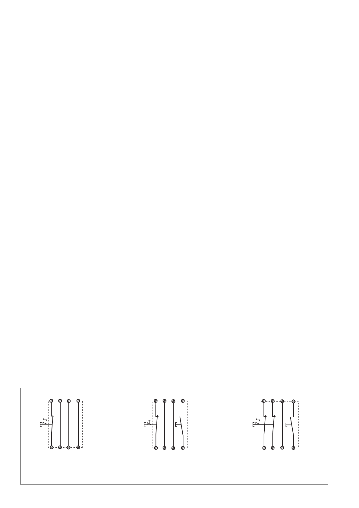
• Circuito de rearme:
- Rearme automático: Puentear S13-S14.
- Rearme manual con supervisión:
Conectar un pulsador entre S33-S34
(S13-S14 abiertos).
• Circuito de entrada:
- Monocanal: Puentear S21-S22 y S31S32. Conectar en S11 y S12 el contacto
normalmente cerrado del elemento
disparador.
- Bicanal sin detección de cortocircuito
transversal: Puentear S21-S22. Conectar
el contacto normalmente cerrado del
elemento disparador en S11-S12 y S11S32.
-
Bicanal con detección de cortocircuito
transversal:
Puentear S11-S12. Conectar
el contacto normalmente cerrado del
elemento disparador en S21-S22 y S31S32.
•
Circuito de realimentación:
Conectar contactores externos en serie al
circuito de rearme S13-S14 o S33-S34.
• Tensión de alimentación de 24 V para la
salida de semicond.: Conectar +24 V DC en
el borne Y31 y 0 V en el borne Y30.
Los contactos de seguridad se activan
(cerrados) y el contacto auxiliar 41-42 se abre.
Se iluminan los indicadores de estado para
“CH.1”, “CH. 2”. El dispositivo está listo para
funcionar. Al abrirse el circuito de entrada, se
abren los contactos de seguridad 13-14/23-24/
33-34 y se cierra el contacto auxiliar 41-42. El
indicador de estado se apaga.
Reactivación
• Cerrar el circuito de entrada.
• En caso de rearme man. con supervisión,
accionar el pulsador entre S33 y S34.
Los indicadores de estado vuelven a iluminarse
y los contactos de seguridad están cerrados.
• Circuito di start:
- Start automatico: ponticellare S13-S14.
- Start manuale controllato: collegare il
pulsante a S33-S34 (S13-S14 aperto)
• Circuito di ingresso:
- Monocanale: ponticellare S21-S22 e
S31-S32. Collegare il contatto NC a S11
e S12.
- Bicanale senza rilevamento del
cortocircuito trasversale: ponticellare
S21-S22. Collegare il contatto NC a S11S12 e S11-S32.
-
Bicanale con rilevamento cortocircuito
trasversale:
ponticellare S11-S12.
Collegare il contatto NC a S21-S22 e
S31-S32.
•
Circuito di retroazione: Collegare in serie i
relè esterni al circuito di start S13-S14 o
S33-S34.
• Tensione di alimentazione di 24 V per
l’uscita a semiconduttore: Collegare +24 V
DC al morsetto Y31 e 0 V al morsetto Y30.
I contatti di sicurezza sono attivati (chiusi) ed
il contatto ausiliario 41-42 è aperto. I LED di
stato per «CH.1», «CH. 2» sono accesi. Il
dispositivo è pronto per il funzionamento. Se
viene aperto il circuito di ingresso i contatti di
sicurezza 13-14/23-24/33-34 si aprono ed il
contatto ausiliare 41-42 si chiude. Il LED di
stato si spegne.
Riattivazione
• Chiudere il circuito di ingresso.
• In caso di start manuale controllato,
azionare il pulsante tra S33 e S34.
Gli indicatori di stato si riaccendono, i contatti
di sicurezza sono chiusi.
• Startcircuit:
- Automatische start: S13-S14 verbinden.
- Handmatige start met bewaking: knop op
S33-S34 aansluiten (S13-S14 open).
• Ingangscircuit:
- Eenkanalig: S21 met S22 en S31 met
S32 verbinden. Verbreekcontact van
bedieningsorgaan op S11 en S12
aansluiten.
- Tweekanalig zonder detectie van
onderlinge sluiting: S21-S22 verbinden.
Verbreekcontact van bedieningsorgaan op
S11-S12 en S11-S32 aansluiten.
-
Tweekanalig met detectie van onderlinge
sluiting:
S11-S12 verbinden.
Verbreekcontact van bedieningsorgaan
op S21-S22 en S31-S32 aansluiten.
•
Terugkoppelcircuit:
Verbreekcontacten van externe
magneetschakelaars in serie met het
startcircuit S13-S14 dan wel S33-S34
aansluiten.
• 24 V voedingsspanning voor halfgeleideruitgang: +24 V DC op klem Y31 en 0 V
op klem Y30 aansluiten.
De veiligheidscontacten zijn geactiveerd
(gesloten) en het hulpcontact 41-42 is
geopend. De status-LED’s voor „CH.1“,
“CH. 2" lichten op. Het apparaat is bedrijfsklaar. Als het ingangscircuit geopend wordt,
gaan de veiligheidscontacten 13-14/23-24/3334 open en het hulpcontact 41-42 sluit. De
status-LED’s doven.
Opnieuw activeren
• Ingangscircuit sluiten.
• Bij handmatige start met bewaking de knop
tussen S33 en S34 bedienen.
De status-LED’s lichten weer op, de
veiligheidscontacten zijn gesloten.
Aplicación
En las Fig. 2 ... a Fig. 11 se presentan
ejemplos de conexión para modo de
conexión de parada de emergencia con
rearme automático y manual, control de
puerta protectora así como multiplicación de
contactos mediante contactores externos.
Por favor tenga en cuenta:
• Fig. 2 y 7: no hay conexión S33-S34
Tenga en cuenta: En caso de caida de
tensión y rearranque, el dispositivo se inicia
automáticamente. Evite un arranque
intempestivo mediante un cableado externo
adecuado.
• Fig. 3, 4, 5, 6, 8:
no hay conexión S13-S14
• Fig. 7: Rearme automático para el control
de puerta protectora: El dispositivo está
preparado para rearmarse con la puerta de
protección abierta por medio del circuito de
rearme S13-S14. Después de cerrarse los
circuitos de entrada S21-S22 y S31-S32
se cerrarán los contactos de seguridad.
S11 S31
S21
S13
S1
Uso
In Fig. 2 ... Fig. 11 sono riportati degli esempi
di collegamento per il cablaggio dell’arresto
di emergenza con start automatico e
controllato, peril controllo finecorsa di ripari
mobili, nonché per l’aumento del numero dei
contatti mediante relè esterni.
Nota bene:
• Fig. 2 e 7: nessun collegamento S33-S34
Il dispositivo si avvia automaticamente dopo la
caduta ed il ritorno dell’alimentazione. Occorre
prevenire un riavvio inatteso usando circuiti
esterni di misura
• Fig. 3, 4, 5, 6, 8:
nessun collegamento S13-S14
• Fig. 7: start automatico per controllo ripari
mobili: Con riparo mobile aperto, il
dispositivo è pronto per lo start attraverso il
circuito di start S13-S14. Dopo la chiusura
dei circuiti di ingresso S21-S22 e S31-S32
i contatti di sicurezza vengono chiusi.
S11 S31
S1
S21
S33
S3
Toepassing
In fig. 2 ... fig. 11 worden aansluitvoorbeelden
gegeven van noodstopschakeling met
automatische en bewaakte start, hekbewaking
en contactvermeerdering door middel van
externe magneetschakelaars.
Let u a.u.b. op het volgende:
• Fig. 2 en 7: geen verbinding S33-S34
Het apparaat start automatisch bij uitvallen
en terugkeren van de spanning. Vermijd
een onverwacht heraanlopen door
maatregelen in de externe schakeling.
• Fig. 3, 4, 5, 6, 8:
geen verbinding S13-S14
• Fig. 7: Automatische start bij hekbewaking:
Het apparaat is bij geopend hek via het
startcircuit S13-S14 startklaar. Na sluiten van
de ingangscircuits S21-S22 en S31-S32
worden de veiligheidscontacten gesloten.
S11
S33
S3
S1
S21
S31
S32
S12
S22
S14
Fig. 2: Circuito de entrada monocanal,
rearme automático/Circuito di ingresso
monocanale, start automatico/Eenkanalig
ingangscircuit, automatische start
S32
S12
S22
S34
Fig. 3: Circuito de entrada monocanal,
rearme supervisado/Circuito di ingresso
monocanale, start controllato/Eenkanalig
ingangscircuit, bewaakte start
- 14 -
S22
S32
S12
S34
Fig.4: Circuito de entrada bicanal, rearme
supervisado/Circuito di ingresso bicanale,
start controllato/Tweekanalig ingangscircuit,
bewaakte start

S11
S21
S31
S33
S21
S11
S33
S21
S13
S11
S1
S12
S22
S32
S3
S34
Fig. 5: Control de puerta protectora
monocanal, rearme supervisado/Controllo
monocanale riparo mobile, start
controllato/Eenkanalige hekbewaking,
bewaakte start
BWS
S11
24 V DC
S12 S22 S34S32
S33S21S31
S3
Fig. 8: Control de barrera fotoeléctrica,
bicanal, detección de corto circuito
transversal mediante BWS, rearme
supervisado/Controllo barriera fotoelettrica,
bicanale, rilevamento del cortocircuito
trasversale mediante fotocellula, start
controllato/
Tweekanalige lichtschermbewaking, detectie van onderlinge sluiting
door lichtscherm, bewaakte start
S1
S22
S3
S31
S2
S32
S12
S34
Fig. 6: Control de puerta protectora bicanal,
rearme supervisado/Controllo bicanale
riparo mobile, start controllato/Tweekanalige
hekbewaking, bewaakte start
1L1
K6
K5
S13 S14
1L2
13
14
K5 K6
Fig. 9: Ejemplo de conexión para
contactores externos, monocanal, rearme
automático/Esempio di collegamento per
relè esterni, monocanale, start automatico/
Aansluitvoorbeeld van externe
magneetschakelaars, eenkanalig, automatische start
S1
S22
S31
S2
S14
S12
S32
Fig. 7: Control de puerta protectora bicanal,
rearme automático/Controllo bicanale
riparo mobile, start automatico/
Tweekanalige hekbewaking, automatische
start
1L1
K6
K5
S33 S34
1L2
S3
13
14
K5 K6
Fig.10: como la Fig. 9 con rearme supervisado/come Fig. 9 con start controllato/
zoals fig. 9 met bewaakte start
SPS
+ 24V
E0.0
E0.1
E0.2
E0.3
A0.0
A0.1
A0.2
A0.3
0V
A2
Y30
Y31
Y32
14
24
34
42
PNOZ X3P
Fig. 11: Ejemplo de conexión para salida
de semiconductor/Esempio di collegamento per uscita a semiconduttore/
Aansluitvoorbeeld van halfgeleideruitgang
Defectos - Averías
• Cortocircuito en el circuito de entrada: La
tensión de alimentación cae y los contactos
de seguridad se abren a través de un
fusible electrónico. Una vez haya
desaparecido la causa del error y se haya
desconectado la tensión de alimentación
durante aprox. 1 minuto, el dispositivo
volverá a estar listo para el servicio.
• Funcionamiento defectuoso de los
contactos: En contactos soldados por
sobrecalentamiento no es posible reactivar
el dispositivo después de abrirse el circuito
de entrada.
• No está encendido el LED “Power”:
Cortocircuito o falta la tensión de
alimentación.
Elemento accionado/Elemento
azionato/Bekrachtigd element
Puerta abierta/riparo aperto/Hek
open
Puerta cerrada/riparo chiuso/
Hek gesloten
S1/S2: Interruptor de parada de emergencia o de puerta protectora/Pulsante di arresto di
emergenza o finecorsa riparo mobile/Noodstop- of hekschakelaar
S3: Pulsador de rearme/Pulsante di start/Startknop
Errori - guasti
• Cortocircuito nel circuito d’ingresso: Un
fusibile elettronico interrompe
l’alimentazione ed i contatti di sicurezza si
aprono. Una volta rimosso la causa del
gausto e interrotto la tensione di
alimentazione, il dispositivo sarà pronto al
funzionamento dopo circa un minuto.
• Malfunzionamenti dei contatti: In caso di
contatti saldati tra loro, non è possibile la
riattivazione dopo l’apertura del circuito di
ingresso.
• Il LED «Power» non si accende:
cortocircuito o mancanza della tensione di
Fouten - Storingen
• Kortsluiting in het ingangscircuit: De
voedingsspanning valt uit en de
veiligheidscontacten worden via een
elektronische zekering geopend. Na het
wegvallen van de storingsoorzaak en het
uitschakelen van de bedrijfsspanning voor
ca. 1 minuut is het apparaat weer
bedrijfsklaar.
• Contactfout: bij verkleefde contacten is na
openen van het ingangscircuit geen nieuwe
activering mogelijk.
• LED „Power“ licht niet op: kortsluiting of
voedingsspanning ontbreekt.
alimentazione.
- 15 -

Datos técnicos
Dati tecnici
Technische gegevens
Datos eléctricos
Tensión de alimentación U
B
Tolerancia de tensión
Consumo de energía con U
B
Rango de frecuencia
Ondulación residual
Tensión y corriente en
circuito de entrada
circuito de rearme
circuito de realimentación
Número de contactos de salida
contactos de seguridad (NA)
contactos auxiliares (N.C.)
Categoría de uso según
EN 60947-4-1
EN 60947-5-1
(DC13: 6 ciclos/Min)
Material de los contactos
Protección externa de los contactos
según EN 60947-5-1 (IK = 1 kA)
fusible de acción rápida
fusible de acción lenta
fusible automático
característica
Salida de semiconductor (resistente a
cortocircuitos)
Alimentación de tensión externa
Tolerancia de la tensión de alimentatión
Resistencia máxima del total de la
línea R
monocanal DC
Circuitos de entrada
lmáx
monocanal AC
bicanal con detección de
derivacion DC
bicanal con detección de
derivacion AC
bicanal sin detección de
cortocircuitos DC
bicanal sin detección de
cortocircuitos AC
Resistencia de entrada mín. en el
instante de la conexión
Datos característicos de técnica
de seguridad
PL según EN ISO 13849-1: 2006
Categoría según EN 954-1
SIL CL según EN IEC 62061
PFH según EN IEC 62061
SIL según IEC 61511
PFD según IEC 61511
TM [año] según EN ISO 13849-1:
2006
Tiempos
Retardo a la conexión
rearme automático
rearme automático tras conexión
de red
rearme supervisado
Retardo a la desconexión
en caso de parada de emergencia
en caso de interrupción del
suministro eléctrico
Tiempo de recuperación con la
frecuencia máxima de 1/s
tras parada de emergencia
tras interrupción del suministro
eléctrico
Simultaneidad canal 1 y 2
Tiempo de espera en caso de rearme
supervisado
Duración mínima de la senal de
arranque con arranque supervisado
Dati elettrici
Tensione di alimentazione U
B
Tolleranza di tensione
Potenza assorbita con U
B
Campo di frequenza
Ondulazione residua
Tensione e corrente su
circuito d’ingresso
circuito di start
circuito di retroazione
Numero dei contatti di uscita
Contatti di sicurezza (NA)
Contatti ausiliari (NC)
Categoria d’uso secondo
EN 60947-4-1
EN 60947-5-1 (DC13: 6 cicli di
commutazione/min)
Materiale di contatto
Fusibile dei contatti, esterno, secondo
norma EN 60947-5-1 (IK = 1 kA)
Fusibile rapido
Fusibile ritardato
Interruttore automatico
Caratteristiche
Uscite a semiconduttore (protette da
corto circuito)
Alimentazione tensione esterna
Tolleranza di alimentatzione
Resistenza totale del conduttore
max. R
a singolo canale DC
circuiti d’ingresso
lmax
canale singolo AC
canale doppio con riconoscimento
del cortocircuito DC
canale doppio con riconoscimento
del cortocircuito AC
bicanale senza riconoscimento di
cortocircuito traversale DC
bicanale senza riconoscimento di
cortocircuito traversale AC
Resistenza di inserzione min.
nella coppia di avvio
Dati tecnici di sicurezza
PL secondo EN ISO 13849-1: 2006
Categoria secondo EN 954-1
SIL CL secondo EN IEC 62061
PFH secondo EN IEC 62061
SIL secondo IEC 61511
PFD secondo IEC 61511
TM [anno] secondo EN ISO 13849-1:
2006
Tempi
Ritardo d’inserzione
Start automatico
Start automatico dopo attivazione
dell'alimentazione di rete
Start controllato
Ritardo di sgancio
in caso di arresto di emergenza
in caso di perdita di alimentazione
Tempo di ripristino per frequenza di
commutazione max. 1/s
dopo arresto di emergenza
dopo perdita di alimentazione
Simultaneità canali 1 e 2
Intervallo di attesa in caso di start
controllato
Durata minima impulso di start con
start controllato
- 16 -
Elektrische gegevens
Voedingsspanning U
B
Spanningstolerantie
Opgenomen vermogen bij U
B
Frequentiebereik
Rimpelspanning
Spanning en stroom op
Ingangscircuit
Startcircuit
Terugkoppelcircuit
Aantal uitgangscontacten
Veiligheidscontacten (M)
Hulpcontacten (V)
Gebruikscategorie volgens
EN 60947-4-1
EN 60947-5-1(DC13: 6
schakelingen/min.)
Contactmateriaal
Contactafzekering extern volgens
EN 60947-5-1 (IK = 1 kA)
Smeltzekering snel
Smeltzekering traag
Zekeringautomaat
Karakteristiek
Halfgeleideruitgangen (kortsluitvast)
Externe voedingsspanning
Spanningstolerantie
Max. weerstand totale kabel R
ingangscircuits
lmax
Eenkanalig DC
eenkanalig AC
Tweekanalig met detectie van
onderlinge sluiting DC
Tweekanalig met detectie van
onderlinge sluiting AC
tweekanalig zonder detectie van
onderlinge sluiting DC
tweekanalig zonder detectie van
onderlinge sluiting AC
Min. ingangsweerstand tijdens
het inschakelmoment
Veiligheidstechnische
kengegevens
PL volgens EN ISO 13849-1: 2006
Categorie volgens EN 954-1
SIL CL volgens EN IEC 62061
PFH volgens EN IEC 62061
SIL volgens IEC 61511
PFD volgens IEC 61511
TM [jaren] volgens
EN ISO 13849-1: 2006
Tijden
Inschakelvertraging
Automatische start
Automatische start na
netinschakeling
Bewaakte start
Afvalvertraging
Bij noodstop
Bij uitvallen spanning
Resettijd bij max. schakelfrequentie
1/s
na noodstop
na uitvallen spanning
Gelijktijdigheid kanaal 1 en 2
Wachttijd bej bewaakte start
Min. startpulsduur bij bewaakte start
24 V AC/DC
-15 ... +10 %
U
= 24 V DC: 2,5 W
B
UB = 24 V AC: 5,0 VA
50 ... 60 Hz
DC: 160 %
UB = 24 V DC: 40 mA
UB = 24 V DC: 70 mA
UB = 24 V DC: 20 mA
3
1
AC1: 240 V/0,01 ... 8 A/
2000 VA
DC1: 24 V/0,01 ... 8 A/
200 W
AC15: 230 V/5 A;
DC13: 24 V/6 A
AgSnO2+ 0,2 µm Au
10 A
6 A
24 V AC/DC: 6 A
B/C
24 V DC, 20 mA
24 V DC
-20 % / +20 %
150 Ohm
180 Ohm
15 Ohm
30 Ohm
300 Ohm
360 Ohm
90 Ohm
PL e (Cat. 4)
Cat. 4
SIL CL 3
2,31E-09
SIL 3
2,03E-06
20
typ. 250 ms, max. 500 ms
typ. 280 ms, max. 550 ms
typ. 35 ms, max. 50 ms
typ. 15 ms, max. 30 ms
typ. 50 ms, max. 70 ms
50 ms
100 ms
∞
300 ms
30 ms

Inmunidad a cortes de tensión
Medio ambiente
CEM
Vibraciones según
EN 60068-2-6
frecuencia
amplitud
Condiciones ambientales
Distancias de fuga y dispersión
superficial según EN 60947-1
Grado de suciedad
Categoría de sobretensión
Tensión de aislamiento de
dimensionado
Resistencia tensión transitoria de
dimensionado
Temperatura ambiente
Temperatura de almacenaje
Tipo de protección
Recinto de montaje (p. ej. armario
de distribución)
carcasa
zona de bornes
Datos mecánicos
Material de la carcasa
carcasa
frente
Sección del conductor externo
(bornes de tornillo)
1 conductor flexible
2 conductores de misma sección,
flexible con terminal, sin
revestimiento de plástico
flexible sin terminal o con terminal
TWIN
Sección del conductor exterior
(bornes de muelle)
flexible sin terminal
Carcasa con bornes de muelle
longitud de pelar
bornes por conexión
Par de apriete para los bornes de tornillo
Dimensiones (bornes de tornillo)
Al x An x Pr
Dimensiones (bornes de muelle)
Al x An x Pr
Posición de montaje
Peso
Ininfluenza mancanza tensione
Dati ambientali
CEM
Oscillazioni secondo la norma
EN 60068-2-6
Frequenza
Ampiezza
Sollecitazione climatica
Caratteristiche dielettriche secondo
la norma EN 60947-1
Grado di contaminazione
Categoria di sovratensione
Tensione nominale di isolamento
Tensione di tenuta agli urti
Temperatura ambiente
Temperatura di magazzinaggio
Grado di protezione
Spazio di montaggio (p. es. quadro
elettrico ad armadio)
Custodia
Zona morsetti
Dati meccanici
Materiale impiegato per la custodia
Custodia
Parte frontale
Sezione del cavo esterno
(morsetti a vite)
1 conduttore, flessibile
2 conduttori con lo stesso diametro,
flessibile con capocorda, senza
manicotto di plastica
flessibile senza capocorda o con
capocorda TWIN
Sezione del conduttore
esterno (morsetti con molla a gabbia)
flessibile senza capocorda
Custodia con morsetti con molla a
gabbia
Lunghezza di spelatura
Prese morsetti per connessione
Coppia di serraggio per i morsetti a vite
Misure (morsetti a vite)
altezza x larghezza x profondità
Misure (morsetti con molla a gabbia)
altezza x larghezza x profondità
Posizione di montaggio
Peso
Maximale spanningsonderbreking
Omgevingscondities
EMC
Trillingsbestendigheid
volgens EN 60068-2-6
Frequentie
Amplitude
Klimaatcondities
Lucht- en kruipwegen volgens
EN 60947-1
Vervuilingsgraad
Oversturingscategorie
Nominale isolatiespanning
Nominale
stootspanningbestendigheid
Omgevingstemperatuur
Opslagtemperatuur
Beschermingsgraad
Inbouwruimte (b.v. schakelkast)
Behuizing
Aansluitklemmen
Mechanische gegevens
Behuizingsmateriaal
Behuizing
Front
Doorsnede van de aansluitkabels
(schroefklemmen)
1 draad, flexibel
2 draaden mad dezelfde doorsnede,
flexibel met adereindhuls, zonder
kunststofhuls
Flexibel zonder adereindhuls of met
TWIN-adereindhuls
Doorsnede van de aansluitkabels
(veerkrachtklemmen)
flexibel zonder adereindhuls
Behuizing met veerkrachtklemmen
Afstriplengte
Klemmen per aansluiting
Aanhaalmoment voor schroefklemmen
Afmetingen (schroefklemmen)
h x b x d
Afmetingen (veerkrachtklemmen)
h x b x d
Inbouwpositie
Gewicht
20 ms
EN 60947-5-1,
EN 61000-6-2,
EN 61000-6-3
10 ... 55 Hz
0,35 mm
EN 60068-2-78
2
III / II
250 V
4 kV
-20 ... + 55 °C
-40 ... +85 °C
IP54
IP40
IP20
PPO UL 94 V0
ABS UL 94 V0
0,25 ... 2,5 mm2, 24 - 12 AWG
0,25 ... 1 mm2, 24 - 16 AWG
0,20 ... 1,5 mm2, 24 - 16 AWG
0,20 ... 1,5 mm2, 24 - 16 AWG
8 mm
2
0,5 Nm
94 x 45 x 121 mm
101 x 45 x 121 mm
cualquiera/a scelta/willekeurig
270 g
- 17 -

ATENCIÓN!
Respetar al pie de la letra las curvas
de vida útil de los relés. Las cifras
características de seguridad de las
salidas de relé valen solo si se
observan los valores de las curvas de
vida útil.
El valor PFH depende de la frecuencia de
conmutación y la carga de las salida de relé.
Mientras no se alcancen las curvas de vida
útil, el valor PFH especificado puede
utilizarse independientemente de la
frecuencia de conmutación y de la carga
porque el valor PFH tiene en cuenta el valor
B10d del relé y las tasas de fallos de los
demás componentes.
En el cálculo de las cifras características de
seguridad deben tenerse en cuenta todas las
unidades que intervienen en una función de
seguridad.
INFORMACIÓN
Los valores SIL/PL de una función de
seguridad no son idénticos a los
valores SIL/PL de los dispositivos
utilizados y pueden diferir de estos.
Recomendamos la herramienta de
software PAScal para calcular los
valores SIL/PL de la función de
seguridad.
ATTENZIONE!
Rispettare le curve di durata dei relè.
I dati tecnici di sicurezza delle uscite
a relè sono valide soltanto se
vengono rispettati i valori delle curve
di durata.
Il valore PFH dipende dalla frequenza di
commutazione e dal carico dell'uscita a relè.
Se non si superano i valori delle curve di
durata, il valore PFH può essere utilizzato
indipendentemente dalla frequenza di
commutazione e dal carico, poiché tale
valore rispetta il valore B10d dei relè e le
percentuali di guasto degli altri componenti.
Tutte le unità impiegate in una funzione di
sicurezza devono essere tenute in
considerazione in fase di calcolo dei valori
nominali relativi al sistema di sicurezza.
INFO
I valori SIL/PL di una funzione di
sicurezza non sono identici ai valori
SIL/PL dei dispositivi utilizzati e
possono quindi variare rispetto a
questi. Per il calcolo dei valori SIL e
PL della funzione di sicurezza si
consiglia l’utilizzo dello strumento
software PAScal.
LET OP!
Let altijd op de levensduurkrommen van
de relais. De veiligheidstechnische
nummers van de relaisuitgangen gelden
slechts zolang de waarden van de
levensduurkrommen aangehouden
worden.
De PFH-waarde is afhankelijk van de
schakelfrequentie en de belasting van de
relaisuitgang.
Zolang de levensduurkrommen niet bereikt
worden, kan de aangegeven PFH-waarde
onafhankelijk van de schakelfrequentie en de
belasting worden gebruikt, omdat de PFHwaarde al uitgaat van de B10d-waarde van de
relais en de uitvalsnelheden van de andere
componenten.
Alle onderdelen van een veiligheidsfunctie
dienen bij berekening van de veiligheidskengegevens in acht te worden genomen.
INFO
De SIL-/PL-waarden van een
veiligheidsfunctie zijn niet gelijk aan
de SIL-/PL-waarden van de gebruikte
apparaten en kunnen hiervan
afwijken. Voor de berekening van de
SIL-/PL-waarden van de
veiligheidsfunctie raden wij het
gebruik van de softwaretool PAScal
aan.
Son válidas las versiones actuales de las
normas 2009-11.
Per le norme citate, sono applicate le versioi
in vigore a 2009-11.
Van toepassing zijn de in 2009-11 actuele
versies van de normen.
Corriente térmica convencional en caso de carga simultánea de varios contactos/Corrente termica
convenzionale con carico contemporaneo dei contatti/Conventionele thermische stroom bij gelijktijdige
belasting van meerdere contacten (AC1, DC1)
Número de contactos/Numero dei contatti/Aantal contacten 3 2 1
Ith (A) para UB AC/con UB AC/per contact bij UB AC 6,0 7,0 8,0
Ith (A) para UB DC/con UB DC/per contact bij UB DC 7,0 8,0 8,0
Datos de pedido/Dati di ordinazione/Bestelgegevens
Tipo/
Tipo/
Type
PNOZ X3P C
PNOZ X3P
Características/
Caratteristiche/
Kenmerken
24 V AC/DC
24 V AC/DC
Bornes/
Morsetti/
Klemmen
borne de muelle/morsetti a molla/veerkrachtklemmen
bornes de tornillo/morsetti a vite/schroefklemmen
Nº de pedido/
N. Ord./
Bestelnr.
787 310
777 310
- 18 -

Curva de vida útil
Las curvas de vida útil indican el número de
ciclos a partir del cual pueden producirse
fallos debidos al desgaste. El desgaste es
producto sobre todo de la carga eléctrica; el
desgaste mecánico es insignificante.
Curva del ciclo di vita
Le curve di durata indicano da quale ciclo di
commutazione è possibile che si verifichino
guasti correlati all'usura. L'usura è causata
principalmente dal carico elettrico, mentre
l'usura meccanica è trascurabile.
Levensduurkrommen
De levensduurkrommen geven aan, vanaf
welk aantal schakelingen met uitvallen door
slijtage rekening moet worden gehouden. De
slijtage wordt vooral veroorzaakt door de
elektrische belasting; de mechanische
slijtage is verwaarloosbaar.
Ejemplo:
Carga inductiva: 0,2 A
Categoría de uso: AC15
Vida útil de los contactos: 4 000 000 ciclos
de conmutación
Mientras la aplicación para realizar necesite
menos de 4 000 000 ciclos, puede utilizarse
el valor PFH (ver "Datos técnicos") para
calcular.
Prever una extinción de chispas suficiente en
todos los contactos de salida para prolongar
la vida útil. En caso de cargas capacitivas,
controlar las puntas de tensión que puedan
crearse. Utilizar diodos volantes para la
extinción de chispas de contactores DC.
Esempio:
Carico induttivo: 0,2 A
Categoria di utilizzo: AC15
Ciclo di vita dei contatti: 4 000 000
commutazioni
Se l'applicazione da realizzare non richiede
più di 4 000 000 cicli di commutazione è
possibile utilizzare il valore PFH (v. dati
tecnici).
Per prolungare il ciclo di vita, dotare tutti i
contatti di uscita di una soppressione
dell'arco sufficiente. Per carichi capacitivi
considerare eventuali picchi di corrente. Per
relè DC utilizzare diodi di protezione per la
soppressione dell'arco.
Voorbeeld:
Inductieve belasting: 0,2 A
Gebruikscategorie: AC15
Levensduur van de contacten: 4 000 000
schakelingen
Zolang de te realiseren toepassing een
aantal schakelingen van minder dan
4 000 000 vereist, kan met de PFH-waarde
(z. Technische gegevens) worden gerekend.
Om de levensduur te verhogen, moet aan
alle uitgangscontacten voor een adequate
vonkblussing gezorgd worden. Bij
capacitieve belasting dienen eventueel
optredende stroompieken vermeden te
worden. Bij DC-magneetschakelaars
vrijloopdioden voor vonkblussing gebruiken.
- 19 -

y
0
3
Dimensiones en mm (")/Dimensioni in mm (")/Afmetingen in mm (")
Carcasa con bornes de tornillo enchufables/
Custodia con morsetti estraibili a vite/
Behuizing met steekbare schroefklemmen/
121 (4.76")
75 (2.95")
87 (3.42")
94 (3.70")
Extraer las bornas enchufables
Colocar un destornillador en el hueco de la
carcasa tras la borna y hacer palanca:
¡ No tirar de las bornas por el cable !
Carcasa con bornes enchufables de muelle/
Custodia con morsetti estraibili a molla/
Behuizing met steekbare veerkrachtklemmen/
45
(1.77")
75 (2.95")
87 (3.42")
101 (3.98")
Rimozione dei morsetti estraibili
Inserire il cacciavite nell’incavo dietro il
connettore e fare leva:
Non estrarre il connettore tirandolo per i cavi!
121 (4.76")
45
(1.77")
Steekbare klemmen uitnemen
Plaats de schroevendraaier in de uitsparing
achter de klemmen en druk de klemmen naar
buiten. De klemmen verwijderen door aan de
kabels te trekken!
Ejemplo de extracción en una borna de
tornillo
Declaración CE de conformidad:
Estos productos cumplen los requisitos de la
Directiva de Máquinas 2006/42/CE del
Parlamento Europeo y del Consejo.
La declaración CE de conformidad completa
pueden encontrarla en la página web de
Internet www.pilz.com
Apoderado: Norbert Fröhlich,
Pilz GmbH & Co. KG, Felix-Wankel-Str. 2,
73760 Ostfildern, Deutschland
Asistencia técnica
+49 711 3409-444 +49 711 3409-444
...
Estamos representados en
muchos países por nuestros
socios comerciales.
Obtendrá más información a
través de nuestra Homepage
o entrando en contacto con
nuestra casa matriz.
Supporto tecnico
... ...
In molti Paesi siamo rappresentati
da partner commerciali.
Per maggiori informazioni potete
contattarci direttamente o tramite
la nostra Homepage.
Esempio di come estrarre un connettore
usando un cacciavite
Dichiarazione di conformità CE:
Questo(i) prodotto(i) soddisfa i requisiti della
Direttiva 2006/42/CE del Parlamento e del
Consiglio Europeo sulle macchine.
Il testo integrale della Dichiarazione di
conformità CE è disponibile in Internet
all’indirizzo www.pilz.com
Mandatario: Norbert Fröhlich,
Pilz GmbH & Co. KG, Felix-Wankel-Str. 2,
73760 Ostfildern, Germania
Technische Support
+49 711 3409-444
In veel landen zijn wij
vertegenwoordigd door
handelspartners.
Voor meer informatie kunt
u onze homepage raadplegen
of contact opnemen met
ons hoofdkantoor.
- 20 -
Als voorbeeld ziet u het verwijderen van
schroefklemmen.
EG-conformiteitsverklaring:
Deze produkten voldoen aan de eisen van de
Europese Machinerichtlijn 2006/42/EG.
De volledige EG-conformiteitsverklaring vindt
u op wwww.pilz.com
Gevolmachtige: Norbert Fröhlich,
Pilz GmbH & Co. KG, Felix-Wankel-Str. 2,
73760 Ostfildern, Duitsland
www
www.pilz.com
Pilz GmbH & Co. KG
Felix-Wankel-Straße 2
73760 Ostfildern, German
Telephone: +49 711 3409Telefax: +49 711 3409-13
E-Mail: pilz.gmbh@pilz.de
Manual de Instrucciones original/Istruzioni originali/Originele bedrijfshandleiding
19907-6NL-05, 2012-02 Printed in Germany
 Loading...