


22173-3FR-02 PSEN sl-0.5n
4 D Betriebsanleitung
4 GB Operating instructions
4 F Manuel d'utilisation
Sicheres Schutztürsystem PSENslock PSENslock safety gate system
Das sichere Schutztürsystem erfüllt die Anforderungen nach
EN 60204-1
EN 60947-5-3: PDF-M zusammen mit dem Betätiger (siehe Technische Daten).
EN 62061: SIL CL 3
EN ISO 13849-1. PL e und Kat. 4
Der Sicherheitsschalter darf nur mit dem zugehörigen Betätiger verwendet werden (siehe Technische Daten).
Die Sicherheitsausgänge müssen 2-kanalig weiterverarbeitet werden.
The safety gate system meets the requirements in accordance with
EN 60204-1
EN 60947-5-3: PDF-M in conjunction with the actuator (see Technical Details).
EN 62061: SIL CL 3
EN ISO 13849-1. PL e and Cat. 4
The safety switch may only be used with the corresponding actuator (see Technical Details).
The safety outputs must use 2-channel processing.
Zu Ihrer Sicherheit |
For your safety |
Installieren und nehmen Sie das Gerät nur |
Only install and commission the unit if you |
dann in Betrieb, wenn Sie diese Betriebsan- |
have read and understood these operating |
leitung gelesen und verstanden haben und |
instructions and are familiar with the applica- |
Sie mit den geltenden Vorschriften über Ar- |
ble regulations for health and safety at work |
beitssicherheit und Unfallverhütung vertraut |
and accident prevention. |
sind. |
Ensure VDE and local regulations are met, |
Beachten Sie die VDEsowie die örtlichen |
especially those relating to safety. |
Vorschriften, insbesondere hinsichtlich |
Any guarantee is rendered invalid if the hous- |
Schutzmaßnahmen |
ing is opened or unauthorised modifications |
Durch Öffnen des Gehäuses oder eigen- |
are carried out. |
mächtige Umbauten erlischt jegliche Ge- |
Do not remove the protective cap until you |
währleistung. |
are just about to connect the unit. |
Entfernen Sie die Schutzkappe erst unmittel- Notice! |
|
bar vor Anschluss des Geräts. |
The magnet surface and counterplate may |
Wichtig! |
heat up. When installing, make sure that |
Die Magnetoberfläche und die Gegenplatte |
heat dissipation is guaranteed. |
können sich erwärmen. Achten Sie bei der |
|
Montage darauf, dass die Wärmeabfuhr ge- |
|
währleistet ist. |
|
Système de sécurité pour protecteurs mobiles PSENslock
Le système de sécurité pour protecteurs mobiles satisfait aux exigences des normes
EN 60204-1
EN 60947-5-3 : PDF-M avec l'actionneur (voir les caractéristiques techniques).
EN 62061 : SIL CL 3
EN ISO 13849-1. PL e et cat. 4
Le capteur de sécurité doit être utilisé uniquement avec l'actionneur correspondant
(voir les caractéristiques techniques).
Les sorties de sécurité doivent être traitées par 2 canaux.
Pour votre sécurité
Vous n'installerez l'appareil et ne le mettrez en service qu'après avoir lu et compris le présent manuel d'utilisation et vous être familiarisé avec les prescriptions en vigueur sur la sécurité du travail et la prévention des accidents.
Respectez les normes locales ou VDE, particulièrement en ce qui concerne la sécurité.
L'ouverture de l'appareil ou sa modification annule automatiquement la garantie.
Veuillez retirer le cache de protection avant de raccorder l'appareil.
Important !
La surface magnétique et la contreplaque peuvent chauffer. Pour le montage, faites attention à ce que l'évacuation de la chaleur soit assurée.
Gerätemerkmale |
Unit features |
Caractéristiques de l'appareil |
|||
Transpondertechnik |
Transponder technology |
Technique à transpondeur |
|||
Gerätevarianten: |
Unit types: |
Modèles d'appareils : |
|||
– |
PSEN sl-0.5n 1.1: codiert |
– |
PSEN sl-0.5n 1.1: coded |
– |
PSEN sl-0.5n 1.1 : codé |
– |
PSEN sl-0.5n 2.1: vollcodiert |
– |
PSEN sl-0.5n 2.1: fully coded |
– |
PSEN sl-0.5n 2.1 : codé multiple |
– |
PSEN sl-0.5n 2.2: unikat codiert |
– |
PSEN sl-0.5n 2.2: uniquely coded |
– |
PSEN sl-0.5n 2.2 : codé unique |
zweikanaliger Betrieb |
Dual-channel operation |
Commande par 2 canaux |
|||
2 Sicherheitsausgänge |
2 safety outputs |
2 sorties de sécurité |
|||
magnetische Zuhaltung für Prozessschutz |
Magnetic guard locking for process protec- |
Interverrouillage magnétique pour la protec- |
|||
1 Eingang zum Ein-/Ausschalten des Zuhal- |
tion |
tion des process |
|||
temagnets |
1 input to switch the locking magnet on/off |
1 entrée pour l'activation / la désactivation |
|||
LED-Anzeige für |
LEDs for |
de l'aimant d'interverrouillage |
|||
– |
Versorgungsspannung/Fehler |
– |
Supply voltage/fault |
LED de visualisation pour |
|
– |
Tür geschlossen |
– |
Gate closed |
– |
tension d'alimentation / erreurs |
– |
Zustand magnetische Zuhaltung |
– State of the magnetic guard locking device |
– |
protecteur mobile fermé |
|
5-poliger M12-Anschlussstecker |
5-pin M12 connector |
– |
état de l'interverrouillage magnétique |
||
|
|
|
|
Connecteur M12 à 5 broches |
|
- 1 -

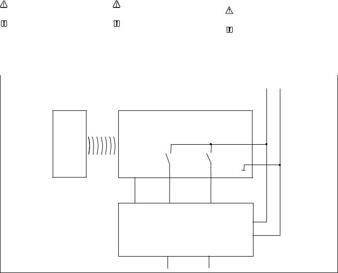
Blockschaltbild Block diagram Schéma de principe
UB
A1 |
A2 |
|
|
Netzteil |
|
12 |
|
Power supply |
|
||
Alimentation |
& |
||
Power / Fault |
|||
|
|||


 22
22
|
S31 |
& |
|
|
|
|
|
|
|
Safety Gate |
Lock |
|
|
|
|
|
|
Empfänger |
Magnet |
|
|
Magnet |
|
|
|
Receiver |
Aimant |
|
|
Récepteur |
|
|
|
Betätiger |
|
|
|
Actuator |
|
|
|
Actionneur |
|
Funktionsbeschreibung |
|
Function description |
Description du fonctionnement |
An den Sicherheitsausgängen 12 und 22 liegt ein High-Signal, wenn gleichzeitig:
der Betätiger im Ansprechbereich ist (Schutztür geschlossen) und
der Eingang S31 high ist (Steuerbefehl für
magnetische Zuhaltung) und der Zuhaltemagnet eingeschaltet ist.
Die Sicherheitsausgänge 12 und 22 sind low, wenn:
Der Betätiger sich außerhalb des Ansprechbereichs befindet oder
der Eingang S31 low ist (Steuerbefehl für magnetische Zuhaltung) und der Zuhaltemagnet ausgeschaltet ist
Magnetische Zuhaltung und Magnetüberwachung
Der Zuhaltemagnet wird eingeschaltet, wenn S31 high ist und der Betätiger erkannt wird (Schutztür geschlossen).
Die Haltekraft des Zuhaltemagneten wird
beim Einschalten getestet. Wenn dieser Test erfolgreich abgeschlossen ist, wechseln die Sicherheitsausgänge in den High-Zustand.
Wird am eingeschalteten Zuhaltemagneten Windungsunterbruch, oder Windungskurzschluss erkannt, wechseln die Sicherheitsausgänge 12 und 22 in den Low-Zustand.
 INFO
INFO
Wenn die Schutztür im zugehaltenen Zustand gewaltsam geöffnet wird, schalten die Sicherheitsausgänge ab.
There is a high signal at safety output 12 and 22 if the following occur simultaneously:
The actuator is within the response range (safety gate closed) and
Input S31 is high (control command for mag-
netic guard locking) and the locking magnet is switched on.
Safety outputs 12 and 22 are low if:
The actuator is outside the response range or
Input S31 is low (control command for magnetic guard locking) and the locking magnet is switched off.
Magnetic guard locking device and magnet monitoring
The locking magnet is switched on if S31 is high and the actuator is detected (safety gate closed).
The holding force of the locking magnet is tested on power-up. If this test is completed successfully, the safety outputs switch to a
high state.
If an open winding or a winding short circuit is detected on a locking magnet that is switched on, safety outputs 12 and 22 switch to a low state.
 INFORMATION
If the safety gate is in a locked condition and is opened by force, the safety outputs will shut down.
Les sorties de sécurité 12 et 22 sont à 1 si, simultanément :
l'actionneur est dans la zone de détection (protecteur mobile fermé) et
l'entrée S31 est à 1 (ordres de commande
avec interverrouillage magnétique) et l'aimant d'interverrouillage est activé.
Les sorties de sécurité 12 et 22 sont à 0 si :
l'actionneur se trouve à l'extérieur de la zone de détection ou si
l'entrée S31 est à 0 (ordres de commande avec interverrouillage magnétique) et l'aimant d'interverrouillage est désactivé.
Interverrouillage magnétique et surveillance magnétique
L'aimant d'interverrouillage est activé si S31 est à l'état « 1 » et si l'actionneur est détecté (protecteur mobile fermé).
La force d'interverrouillage de l'aimant est testée lors de l'activation. Si ce test a été ef-
fectué avec succès, les sorties de sécurité passent à l'état « 1 ».
Si une coupure de la bobine ou un court-circuit de la bobine est détecté sur l'aimant d'interverrouillage activé, les sorties de sécurité 12 et 22 passent à l'état « 0 ».
 INFORMATION
Si le protecteur mobile en position fermée est ouvert par la force, les sorties de sécurité sont désactivées.
Seitenund Höhenversatz |
Lateral and vertical offset |
Décalage latéral et en hauteur |
Höhenversatz/Vertical offset/Décalage vertical |
Seitenversatz/Lateral offset/ |
|||
|
|
|
|
Décalage latéral |
Lock |
Input |
Gate Safety |
Fault / Power |
|
Höhenversatz max. 5 mm |
|
Vertical offset max. 5 mm |
Décalage en hauteur max. 5 mm |
|
Seitenversatz max. 3 mm |
|
Lateral offset max. 3 mm |
Décalage latéral max. 3 mm |
|
- 2 -

Verdrahtung
Beachten Sie:
Angaben im Abschnitt "Technische Daten" unbedingt einhalten.
Wiring
Please note:
Information given in the "Technical details" must be followed.
Raccordement
Important :
Respecter impérativement les données indiquées dans le paragraphe « Caractéristiques techniques ».
Hinweise zur Leitungslänge |
Guidelines for cable length |
Remarques concernant la longueur des câ- |
||
Die max. Leitungslänge ist abhängig vom |
The max. cable length depends on the voltage |
bles |
||
Spannungsabfall an den Leitungen zum Sen- |
drop at the sensor cables. The level of voltage |
La longueur maximale des câbles dépend de la |
||
sor. Die Höhe des Spannungsabfalls wird be- |
drop is determined by the: |
chute de tension dans les câbles utilisés pour le |
||
stimmt durch: |
Cable resistance |
capteur. Le niveau de la chute de tension est |
||
den Leitungswiderstand |
Current of the device and the current load of |
déterminée par : |
||
den Strom des Gerätes und der Strombela- |
the safety outputs 12 and 22 |
la résistance du câble |
||
stung der Sicherheitsausgänge 12 und 22 |
If the level of the supply voltage at the device |
le courant de l'appareil et la charge électri- |
||
Wird die minimal zulässige Versorgungsspan- |
connector falls below the minimum permitted |
que des sorties de sécurité 12 et 22. |
||
nung am Stecker des Geräts unterschritten |
value (see Technical details), the electromagnet |
Si la tension d'alimentation minimale autorisée |
||
(s. technische Daten), wird der Elektromagnet |
is no longer activated reliably. The "Lock" LED |
est inférieure au connecteur de l'appareil (voir |
||
nicht mehr zuverlässig angesteuert. Die LED |
registers an error when guard locking. |
les caractéristiques techniques), l'aimant élec- |
||
"Lock" meldet einen Fehler bei der Zuhaltung. |
Possible remedies: |
trique n'est plus commandé en toute fiabilité. |
||
Mögliche Abhilfen: |
Set the supply voltage constantly to the up- |
La LED « Lock » signale une erreur lors de l'in- |
||
Versorgungsspannung dauerhaft auf den |
per tolerance range (see Technical details) |
terverrouillage. |
||
oberen Toleranzbereich (siehe technische |
Select a higher cable cross section |
Remèdes possibles : |
||
Daten) einstellen |
Reduce the load on the safety output, e.g. |
Paramétrer la tension d'alimentation dura- |
||
höheren Leiterquerschnitt wählen |
with an electrical evaluation device |
blement sur la plage de tolérance supérieure |
||
Last am Sicherheitsausgang reduzieren, |
(PNOZ e11p, 5 mA/channel) |
(voir les caractéristiques techniques) |
||
z. B. mit elektrischem Auswertegerät |
|
|
Sélectionner une section du fil plus impor- |
|
(PNOZ e11p, 5 mA/Kanal) |
|
|
tante |
|
|
|
|
Réduire la charge sur la sortie de sécurité, |
|
|
|
|
par exemple, avec une unité de contrôle |
|
|
|
|
électrique (PNOZ e11p, 5 mA/canal) |
|
Empfohlene Leiterquerschnitte |
Recommended cable cross sections |
Section des câbles recommandée |
||
Voraussetzung: |
Prerequisite: |
Condition préalable : |
||
Versorgungsspannung: 24 V |
Supply voltage: 24 V |
Tension d'alimentation : 24 V |
||
Leitungstyp: LiYY 5x0,25 mm² (79 Ohm/km) |
Cable type: LiYY 5x0.25 mm² (79 Ohm/km) |
Type de câble : LiYY 5x0,25 mm² (79 Ohm/ |
||
von Pilz |
from Pilz |
km) de Pilz |
||
|
|
|
|
|
Max. Last pro Sicherheitsausgang |
|
100 mA |
|
500 mA |
|
|
|
|
|
Leitungslänge |
|
65 m |
|
28 m |
|
|
|
|
|
Wenn Leitungslängen größer als in der Tabelle angegeben benötigt werden, dann nehmen Sie bitte Kontakt mit Pilz auf.
If cable lengths greater than those stated in the table are required, please contact Pilz.
Si des longueurs de câbles plus grandes que celles indiquées dans le tableau sont nécessaires, veuillez prendre contact avec Pilz.
Anschlüsse |
|
Connections |
|
Raccordements |
|
Stiftstecker 5-pol. M12 (male) |
Connector 5 pin M12 (male) |
Connecteur mâle M12 à 5 broches |
|||
|
|
4 |
3 |
|
|
|
|
|
5 |
|
|
|
|
1 |
2 |
|
|
|
|
|
|
|
|
Anschlussbelegung |
|
Pin assignment |
|
Affectation des bornes |
|
|
|
|
|
|
|
PIN/ |
Funktion/ |
|
Klemmenbezeichnung/ |
|
Adernfarbe (Pilz Kabel)/ |
Broche |
Function/ |
|
Terminal designation/ |
|
Cable colour (Cable Pilz)/ |
|
Foncion |
|
Désignation des bornes |
|
Couleur du fil (fil de Pilz) |
1 |
+24 UB |
|
A1 |
|
braun/brown/marron |
|
|
|
|
|
|
2 |
Ausgang Kanal 1/ |
|
12 |
|
weiß/white/blanc |
|
Output, channel 1/ |
|
|
|
|
|
Canal de sortie 1 |
|
|
|
|
|
|
|
|
|
|
3 |
0 V UB |
|
A2 |
|
blau/blue/bleu |
|
|
|
|
|
|
4 |
Ausgang Kanal 2/ |
|
22 |
|
schwarz/black/noir |
|
Output, channel 2/ |
|
|
|
|
|
Canal de sortie 2 |
|
|
|
|
|
|
|
|
|
|
5 |
"Lock_Unlock" |
|
S31 |
|
grau/grey/gris |
|
|
|
|
|
|
- 3 -
Anschluss an Auswertegeräte |
Connection to evaluation devices |
Raccordement aux appareils de contrôle |
Bitte beachten Sie: |
Please note: |
Tenez compte de ce qui suit : |
das Netzteil muss den Vorschriften für Klein- |
The power supply must meet the regulations |
Cette alimentation doit être conforme aux |
spannungen mit sicherer Trennung (SELV, |
for extra low voltages with safe separation |
prescriptions relatives aux basses tensions à |
PELV) entsprechen. |
(SELV, PELV). |
séparation galvanique (SELV, PELV). |
die Einund Ausgänge des Sicherheitsschal- |
the inputs and outputs of the safety switch |
Les entrées et les sorties du capteur de sé- |
ters müssen eine sichere Trennung zu Span- |
must have a safe separation to voltages over |
curité doivent posséder une séparation gal- |
nungen über 60 V AC besitzen. |
60 V AC. |
vanique pour les tensions supérieures à |
|
|
60 V AC. |
ACHTUNG! |
CAUTION! |
|
Die Sicherheitsausgänge müssen 2-ka- |
The safety outputs must use 2-channel |
ATTENTION ! |
nalig weiterverarbeitet werden. |
processing. |
Les sorties de sécurité doivent être trai- |
INFO |
INFORMATION |
tées par 2 canaux. |
Sicherheitsschaltgeräte mit Weitspan- |
Safety relays with universal power supply |
INFORMATION |
nungsnetzteil oder in der Geräte-Variante |
or in AC unit versions have internal poten- |
Les blocs logiques de sécurité avec ali- |
AC haben eine interne Potenzialtrennung |
tial isolation and are not suitable as evalua- |
mentation universelle ou les variantes d'ap- |
und sind als Auswertegeräte nicht geeig- |
tion devices. |
pareils AC disposent d'une isolation |
net. |
|
galvanique interne et ne conviennent pas |
|
|
en tant qu'unités de contrôle. |
Einzelschaltung |
Single connection |
Montage simple |
|
|
24 V 0 V |
Betätiger/ |
Empfänger/ |
Actuator/ |
Reciever/ |
Actioneur |
Recépteur |
A1
A2
S31 |
12 |
22 |
O1 (ST) |
I1 (FS) |
I2 (FS) |
Auswertegerät/
Evaluation device/ A1
Appareil de surveillance
A2
FS: Fail-safe
ST: Standard
- 4 -

Anschluss an PNOZ X, PNOZpower, |
Connection to PNOZ X, PNOZpower, |
Raccordement aux PNOZ X, PNOZpower, |
||||||||||||
PNOZsigma, PNOZelog |
PNOZsigma, PNOZelog |
PNOZsigma, PNOZelog |
||||||||||||
|
|
|
|
|
|
|
|
|
|
|
|
|
|
|
|
PNOZ |
|
|
|
|
|
|
|
PSENslock |
|||||
|
|
|
0 V |
24 V |
|
|||||||||
PNOZ X2.7P (No. 777 305*, 787 305*) |
A1 |
|
|
|
|
|
|
|
|
|
|
|
1 A1 |
|
|
|
|
|
|
|
|
|
|
|
|
||||
|
|
|
|
|
|
|
|
|
|
|
||||
A2 |
|
|
|
|
|
|
|
|
|
|
|
3 A2 |
||
PNOZ X2.8P (No. 777 301*, 787 301*) |
|
|
|
|
|
|
|
|
|
|
|
|||
|
|
|
|
|
|
|
|
|
|
|
|
|
|
|
PNOZ X4 (No. 774 730) |
|
|
|
|
|
|
|
|
|
|
|
|
|
|
PNOZ X8P (No. 777 760, 787 760) |
S21 |
|
|
|
|
|
|
|
|
5 |
S31 |
|||
PNOZ X9P (No. 777 609, 787 609) |
|
|
|
|
|
|
|
|||||||
|
|
|
|
|
|
|
|
|
|
|
|
|
|
|
|
S22 |
|
|
|
|
|
|
|
|
|
|
2 |
12 |
|
|
|
|
|
|
|
|
|
|
|
|
||||
|
S12 |
|
|
|
|
|
|
|
|
|
|
|||
|
|
|
|
|
|
|
|
|
|
|
||||
|
S52 |
|
|
|
|
|
|
|
|
|
4 |
22 |
||
|
|
|
|
|
|
|
|
|
|
|||||
|
|
|
|
|
|
|
|
|
|
|
|
|
|
|
|
PNOZ |
|
|
|
|
|
|
|
PSENslock |
|||||
|
|
|
0 V |
24 V |
|
|||||||||
|
A1 |
|
|
|
|
|
|
|
|
|
|
|
1 A1 |
|
|
|
|
|
|
|
|
|
|
|
|
|
|||
|
|
|
|
|
|
|
|
|
|
|
|
|||
PNOZ X3P (No. 777 310*, 787 310*) |
A2 |
|
|
|
|
|
|
|
|
|
|
|
3 A2 |
|
|
|
|
|
|
|
|
|
|
|
|
||||
S21 |
|
|
|
|
|
|
|
|
|
|
|
5 S31 |
||
PNOZ X3.10P (No. 777 314*, 787 314*) |
S22 |
|
|
|
|
|
|
|
|
|
|
|
|
|
PNOZ XV3P |
|
|
|
|
|
|
|
|
|
|
|
|
|
|
|
|
|
|
|
|
|
|
|
|
|
|
|
||
PNOZ XV3.1P (No. 777 520, 787 520, 777 522, 787 522, 777525) |
|
|
|
|
|
|
|
|
|
|
|
|
|
|
|
S12 |
|
|
|
|
|
2 |
12 |
||||||
|
|
|
|
|
|
|
|
|
||||||
|
S32 |
|
|
|
|
|
4 |
22 |
||||||
|
|
|
|
|
|
|
|
|
||||||
|
|
|
|
|
|
|
|
|
|
|
|
|
|
|
|
PNOZ |
|
|
|
|
|
|
|
PSENslock |
|||||
|
|
|
0 V |
24 V |
|
|||||||||
|
A1 |
|
|
|
|
|
|
|
|
|
|
|
1 A1 |
|
|
|
|
|
|
|
|
|
|
|
|
|
|||
|
|
|
|
|
|
|
|
|
|
|
|
|||
|
A2 |
|
|
|
|
|
|
|
|
|
|
|
3 A2 |
|
|
|
|
|
|
|
|
|
|
|
|
|
|||
PNOZ s3 |
5 S31 |
|
PNOZ s4 (No. 750 104, 751 104) |
||
PNOZ s4.1 (No. 750 124, 751 124) |
|
|
PNOZ s5 (No. 750 105, 751 105, 751 185) |
|
|
PNOZ X5 (No. 774 325*) |
|
|
S12 |
2 |
12 |
S22 |
4 |
22 |
PNOZ |
PSENslock |
|
0 V |
24 V |
|
A1 |
1 A1 |
|
A2 |
3 A2 |
|
PNOZ X2.9P |
5 |
S31 |
|
|
|
S12 |
2 |
12 |
S52 |
4 |
22 |
- 5 -
 Loading...