


 Loading...
PNOZmulti 2 Communication Interfaces
Configurable Control System PNOZmulti
Operating Manual1002971EN02
This document is a translation of the original document.
All rights to this documentation are reserved by Pilz GmbH & Co. KG. Copies may be made for internal purposes. Suggestions and comments for improving this documentation will be gratefully received.
Pilz®, PIT®, PMI®, PNOZ®, Primo®, PSEN®, PSS®, PVIS®, SafetyBUS p®, SafetyEYE®, SafetyNET p®, the spirit of safety® are registered and protected trademarks of Pilz GmbH & Co. KG in some countries.
 SD means Secure Digital

Content
Section 1 |
Introduction |
7 |
||
|
|
1.1 |
Definition of symbols |
7 |
|
|
|
|
|
Section 2 |
Overview Communication options |
8 |
||
|
|
2.1 |
Communication via the fieldbus modules |
8 |
|
|
2.2 |
Communication via the communication modules |
9 |
|
|
2.3 |
Communication via Modbus TCP |
10 |
|
|
|
|
|
Section 3 |
Safety |
|
11 |
|
|
|
3.1 |
Intended use |
11 |
|
|
3.2 |
Safety regulations |
11 |
|
|
3.2.1 |
Use of qualified personnel |
11 |
|
|
3.2.2 |
Warranty and liability |
11 |
|
|
3.2.3 |
Disposal |
12 |
|
|
|
|
|
Section 4 |
Fieldbus Modules |
13 |
||
|
|
4.1 |
Basics |
13 |
|
|
4.1.1 |
Input data (to the PNOZmulti 2) |
13 |
|
|
4.1.2 |
Output data (from the PNOZmulti 2) |
14 |
|
|
4.1.3 |
Overview of tables |
15 |
|
|
4.1.4 |
Access to table segments |
15 |
|
|
4.1.4.1 |
Example 1 Access successful |
16 |
|
|
4.1.4.2 |
Example 2 Access failed |
17 |
|
|
4.2 |
PNOZ m ES Profibus |
18 |
|
|
4.2.1 |
Input and output data |
18 |
|
|
4.2.2 |
Access to table segments |
19 |
|
|
4.2.3 |
LED status |
19 |
|
|
4.2.4 |
Diagnostic data PNOZ m ES Profibus |
19 |
|
|
4.3 |
PNOZ m ES CANopen |
22 |
|
|
4.3.1 |
Service Data Objects (SDOs) |
22 |
|
|
4.3.2 |
Process Data Objects (PDOs) |
22 |
|
|
4.4 |
PNOZ m ES EtherCAT |
24 |
|
|
4.4.1 |
Service Data Objects (SDOs) |
24 |
|
|
4.4.2 |
Process Data Objects (PDOs) |
24 |
|
|
4.5 |
PNOZ m ES Powerlink |
25 |
|
|
4.5.1 |
Service Data Objects (SDOs) |
25 |
|
|
4.5.2 |
Process Data Objects (PDOs) |
25 |
|
|
|
|
|
Section 5 |
Communication modules |
26 |
||
|
|
5.1 |
Overview |
26 |
|
|
5.2 |
PNOZ m ES RS232 |
26 |
|
|
5.3 |
PNOZ m ES ETH |
26 |
|
|
5.3.1 |
Introduction |
26 |
|
|
5.3.2 |
Overview |
26 |
|
|
5.3.3 |
Module features |
27 |
|
|
5.3.4 |
Modbus/TCP |
27 |
|
|
5.3.5 |
RJ45 interfaces ("Ethernet") |
27 |
|
|
5.3.6 |
Requirements of the connection cable and connector |
27 |
|
|
|
|
|
Operating Manual PNOZmulti 2 Communication Interfaces |
3 |
|||
1002971EN02 |
|
|
|
|

Content
|
|
5.3.7 |
Interface configuration |
28 |
|
|
5.3.8 |
RJ45 connection cable |
28 |
|
|
5.3.9 |
Process data exchange |
28 |
|
|
5.4 |
Communication procedure |
29 |
|
|
5.5 |
Telegram structure |
30 |
|
|
5.5.1 |
Header |
30 |
|
|
5.5.2 |
Usable data |
31 |
|
|
5.5.3 |
Footer |
31 |
|
|
5.6 |
Usable data |
32 |
|
|
5.6.1 |
Virtual inputs (Input Byte 0 ... Input Byte 15) |
32 |
|
|
5.6.1.1 |
Watchdog |
32 |
|
|
5.6.2 |
Virtual outputs (Output Byte 0 ... Output Byte 15) |
32 |
|
|
5.6.3 |
LED status |
32 |
|
|
5.6.4 |
Tables |
33 |
|
|
5.7 |
Requests |
33 |
|
|
5.7.1 |
Mask (Mask Byte 0 ... Mask Byte 15) |
33 |
|
|
5.7.2 |
Send virtual inputs to the PNOZmulti |
34 |
|
|
5.7.3 |
Send virtual inputs to the PNOZmulti, request state of the virtual outputs |
35 |
|
|
|
and LED status from the PNOZmulti |
|
|
|
5.7.3.1 |
Control Byte (Byte 40) |
36 |
|
|
5.7.4 |
Request state of virtual inputs and outputs from PNOZmulti |
38 |
|
|
5.7.5 |
Request data from the PNOZmulti in table form |
38 |
|
|
5.7.6 |
Send input and output data (cf. fieldbus communication) |
39 |
|
|
5.7.6.1 |
Input data (to the PNOZmulti) |
40 |
|
|
5.7.6.2 |
Output data (from the PNOZmulti) |
41 |
|
|
5.7.6.3 |
Control Byte (Byte 5) |
42 |
|
|
5.8 |
Troubleshooting |
44 |
|
|
5.8.1 |
Request format does not meet specifications |
44 |
|
|
5.8.2 |
Error while executing a request |
44 |
|
|
|
|
|
Section 6 |
Modbus/TCP |
45 |
||
|
|
6.1 |
System requirements |
45 |
|
|
6.2 |
Modbus/TCP Basics |
45 |
|
|
6.3 |
Modbus/TCP with PNOZmulti 2 |
46 |
|
|
6.4 |
Data areas |
47 |
|
|
6.4.1 |
Overview |
47 |
|
|
6.4.2 |
Function codes |
48 |
|
|
6.4.3 |
Data transfer limits |
49 |
|
|
6.4.4 |
Input and output data, watchdog |
49 |
|
|
6.4.5 |
Allocation table of the virtual inputs and outputs |
52 |
|
|
6.4.6 |
Process data, base unit |
52 |
|
|
6.4.7 |
Process data, righthand expansion modules |
54 |
|
|
6.4.8 |
Process data, lefthand expansion modules |
64 |
|
|
6.4.9 |
Process data, fieldbus and communication module |
71 |
|
|
6.4.10 |
Diagnostic words |
74 |
|
|
6.4.11 |
Enable elements |
80 |
|
|
6.4.12 |
Project data |
81 |
|
|
6.4.13 |
Device data, base unit |
83 |
|
|
|
|
|
Operating Manual PNOZmulti 2 Communication Interfaces |
4 |
|||
1002971EN02 |
|
|
|
|

Content
|
6.4.14 |
Device data, righthand expansion modules |
84 |
|
6.4.15 |
Device data, lefthand expansion modules |
89 |
|
6.4.16 |
Device data, fieldbus and communication module |
93 |
|
6.4.17 |
LEDs |
94 |
|
6.4.18 |
Updating the data areas |
95 |
|
6.5 |
Examples of Clients and Servers |
96 |
|
|
|
|
Section 7 |
Diagnostic word |
97 |
|
|
7.1 |
Introduction |
97 |
|
7.2 |
Elements with diagnostic word |
97 |
|
7.3 |
Structure of the diagnostic word |
97 |
|
7.4 |
Evaluate diagnostic word |
98 |
|
7.5 |
Example Evaluate diagnostic word of a safety gate |
100 |
|
|
|
|
Section 8 |
Appendix |
101 |
|
|
8.1 |
Tables |
101 |
|
8.1.1 |
Table 20 Process data, base unit |
101 |
|
8.1.2 |
Table 21 Process data, righthand expansion modules |
103 |
|
8.1.3 |
Table 22 Process data, lefthand expansion modules |
107 |
|
8.1.4 |
Table 23 Process data, fieldbus and communication module |
111 |
|
8.1.5 |
Table 70 Diagnostic words |
114 |
|
8.1.6 |
Table 71 Enable elements |
117 |
|
8.1.7 |
Table 80 Project data |
118 |
|
8.1.8 |
Table 90 Device data, base unit |
119 |
|
8.1.9 |
Table 91 Device data, righthand expansion modules |
120 |
|
8.1.10 |
Table 92 Device data, lefthand expansion modules |
122 |
|
8.1.11 |
Table 93 Device data, fieldbus and communication module |
123 |
|
8.2 |
Object directory, Service Data Objects (SDOs) |
124 |
|
8.2.1 |
Structure of the object directory |
124 |
|
8.2.2 |
Output data SDO Index 0x2000 |
126 |
8.2.3Process data, base unit and 1st righthand expansion module SDO Index 127 0x2001
8.2.4 |
Process data, 2nd ... 4th righthand expansion module SDO Index |
130 |
|
0x2002 |
|
8.2.5Process data, 5th ... 6th righthand expansion module SDO Index 0x2003134
8.2.6Process data, 1st ... 3rd lefthand expansion module SDO Index 0x2007 136
8.2.7 |
Process data, 4th lefthand expansion module SDO Index 0x2008 |
140 |
8.2.8 |
Process data, fieldbus SDO Index 0x2009 |
142 |
8.2.9 |
Diagnostic words SDO Index 0x200A |
143 |
8.2.10 |
Diagnostic words and enable elements SDO Index 0x200B |
143 |
8.2.11 |
Project data SDO Index 0x200D |
144 |
8.2.12Device data, base unit and 1st righthand expansion module SDO Index 146 0x200F
8.2.13Device data, 2nd ... 4th righthand expansion module SDO Index 0x2010 148
8.2.14Device data, 5th ... 6th righthand expansion module SDO Index 0x2011 150
|
8.2.15 Device data, 1st ... 3rd lefthand expansion module SDO Index 0x2015 |
151 |
|
8.2.16 Device data, 4th lefthand expansion module SDO Index 0x2016 |
152 |
|
8.2.17 Device data, fieldbus and communication module SDO Index 0x2017 |
153 |
|
|
|
Operating Manual PNOZmulti 2 Communication Interfaces |
5 |
|
1002971EN02 |
|
|

Content
8.2.18 |
Input data SDO Index 0x2100 |
154 |
8.3 |
Assignment of system and I/OLEDs |
155 |
Operating Manual PNOZmulti 2 Communication Interfaces |
6 |
1002971EN02 |
|

Introduction
1 Introduction
1.1Definition of symbols
Information that is particularly important is identified as follows:
DANGER!
This warning must be heeded! It warns of a hazardous situation that poses an immediate threat of serious injury and death and indicates preventive measures that can be taken.
WARNING!
This warning must be heeded! It warns of a hazardous situation that could lead to serious injury and death and indicates preventive measures that can be taken.
CAUTION!
This refers to a hazard that can lead to a less serious or minor injury plus material damage, and also provides information on preventive measures that can be taken.
NOTICE
This describes a situation in which the product or devices could be dam aged and also provides information on preventive measures that can be taken. It also highlights areas within the text that are of particular import ance.
INFORMATION
This gives advice on applications and provides information on special fea tures.
Operating Manual PNOZmulti 2 Communication Interfaces |
7 |
1002971EN02 |
|
Overview Communication options
2 |
Overview Communication options |
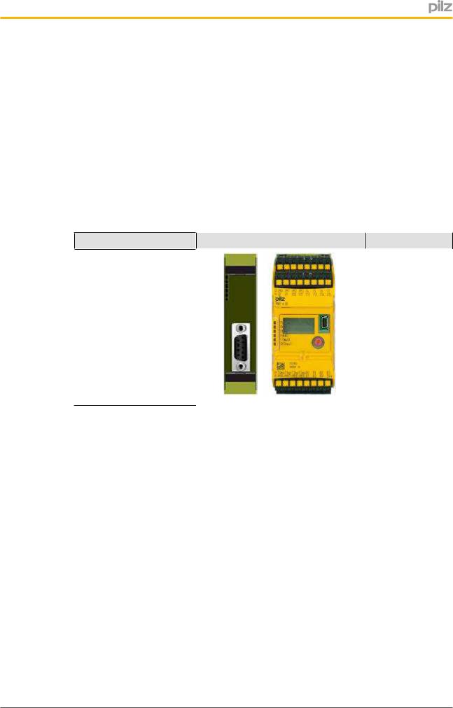
2.1Communication via the fieldbus modules
With communication via the fieldbus modules, the data area provided by the PNOZmulti 2 for communication is divided into subsections, which are stored in tables. Each table con sists of one or more segments.
The Master (PC, PLC) can request a segment from a table. This is delivered with the next response telegram. The input and output data is also transmitted in each telegram.
Communication via the fieldbus modules is described in detail in the chapter entitled Field bus Modules [ 13].
13].
The following device combinations are possible:
Fieldbus modules |
Base units |
PNOZ m ES Profibus
PNOZ m ES CANopen PNOZ m B0 PNOZ m ES EtherCAT
PNOZ m ES Powerlink
Operating Manual PNOZmulti 2 Communication Interfaces |
8 |
1002971EN02 |
|
Overview Communication options
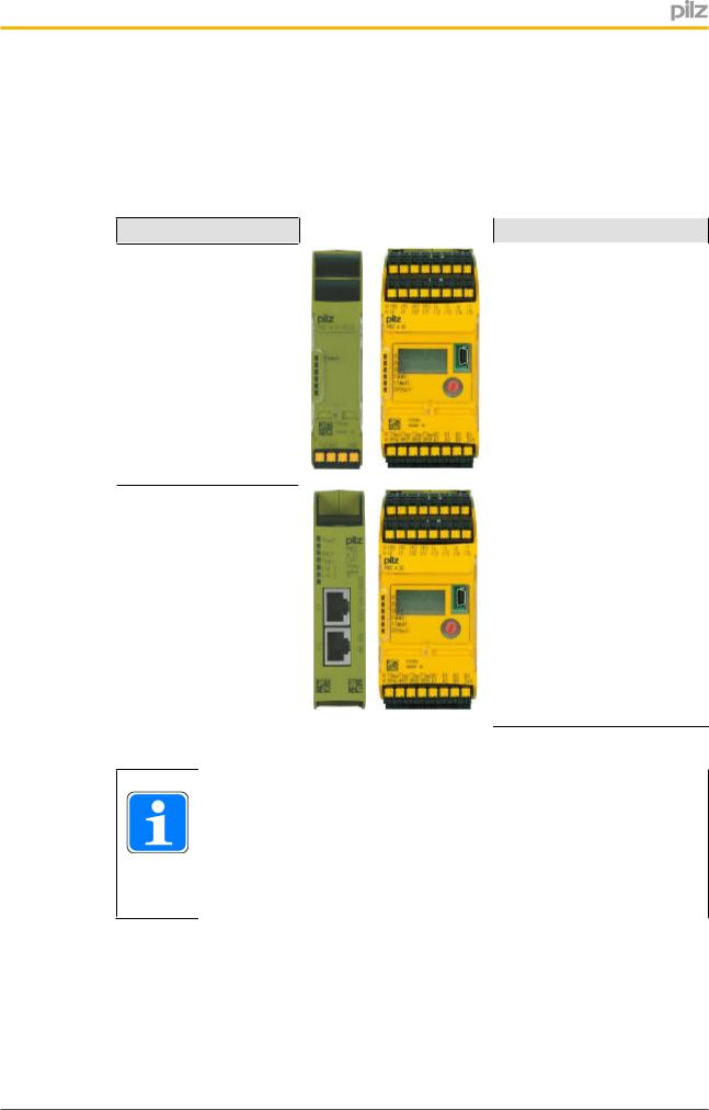
2.2Communication via the communication modules
When communication takes place via a communication module, data exchange is defined via a special protocol. This protocol is described in more detail in the chapter entitled Com munication modules [ 26].
26].
The following device combinations are possible:
Communication Module  Base units
PNOZ m ES RS232
PNOZ m B0
PNOZ m ES ETH
INFORMATION
If virtual inputs/outputs are to be downloaded via the communication module (without using a fieldbus module), the interface "Inputs/outputs that are downloaded via the integrated interface" must be configured in the hard ware configuration in the PNOZmulti Configurator.
Operating Manual PNOZmulti 2 Communication Interfaces |
9 |
1002971EN02 |
|

Overview Communication options
2.3Communication via Modbus TCP
For data exchange with Modbus/TCP, the PNOZmulti 2 is the connection server. All the diagnostic data is defined in one data record, to which the client has direct access.
Communication with Modbus/TCP is described in detail in the chapter entitled Modbus/TCP [ 45].
45].
The following device combinations are possible:
Communication Module |
Base unit |
PNOZ m ES ETH |
PNOZ m B0 |
INFORMATION
If virtual inputs/outputs are to be downloaded via the communication module (without using a fieldbus module), the interface "Inputs/outputs that are downloaded via the integrated interface" must be configured in the hard ware configuration in the PNOZmulti Configurator.
Operating Manual PNOZmulti 2 Communication Interfaces |
10 |
1002971EN02 |
|
Safety
3 Safety
3.1Intended use
The communication interface on the configurable control system PNOZmulti 2 is used to transfer diagnostic data to an application program. This data may only be used for non safety purposes, e.g. visualisation.
NOTICE
For details of the intended use and application of the configurable control system PNOZmulti 2 please refer to the operating instructions for the re spective unit.
The following is deemed improper use in particular:
}Any component, technical or electrical modification to a product
}Use of a product outside the areas described in the product documentation
}Any use that is not in accordance with the documented technical details.
3.2Safety regulations
3.2.1Use of qualified personnel
The products may only be assembled, installed, programmed, commissioned, operated, maintained and decommissioned by competent persons.
A competent person is someone who, because of their training, experience and current pro fessional activity, has the specialist knowledge required to test, assess and operate the work equipment, devices, systems, plant and machinery in accordance with the general standards and guidelines for safety technology.
It is the company’s responsibility only to employ personnel who:
}Are familiar with the basic regulations concerning health and safety / accident preven tion
}Have read and understood the information provided in this description under "Safety"
}And have a good knowledge of the generic and specialist standards applicable to the specific application.
3.2.2Warranty and liability
All claims to warranty and liability will be rendered invalid if
}The product was used contrary to the purpose for which it is intended
}Damage can be attributed to not having followed the guidelines in the manual
}Operating personnel are not suitably qualified
}Any type of modification has been made (e.g. exchanging components on the PCB boards, soldering work etc.).
Operating Manual PNOZmulti 2 Communication Interfaces |
11 |
1002971EN02 |
|

Safety
3.2.3Disposal
}In safetyrelated applications, please comply with the mission time tM in the safetyre lated characteristic data.
}When decommissioning, please comply with local regulations regarding the disposal of electronic devices (e.g. Electrical and Electronic Equipment Act).
Operating Manual PNOZmulti 2 Communication Interfaces |
12 |
1002971EN02 |
|

Fieldbus Modules
4 |
Fieldbus Modules |
4.1Basics
The input and output range is each reserved an area of 32 Bytes for communication via fieldbuses; this is updated approx. every 15 ms. The Master (PC, PLC) can send 32 Bytes to the PNOZmulti 2 and receive 32 Bytes from the PNOZmulti 2. The Master can process the information in bytes, words or in double words.
4.1.1Input data (to the PNOZmulti 2)
Double Word |
Word |
Byte |
Content |
|
|
|
|
|
|
0 |
0 |
0 |
State of virtual inputs on the PNOZmulti 2 |
|
|
|
|
fieldbus module. |
|
|
|
1 |
||
|
|
The inputs are defined in the PNOZmulti |
||
|
|
|
||
|
1 |
2 |
||
|
Configurator. Each input that is used is |
|||
|
|
3 |
given a number there, e.g. i0, i5... |
|
|
|
|
The state of input i0 is stored in bit 0 of |
|
1 |
2 |
4 |
||
byte 0; the state of input i5 is stored in bit 5 |
||||
|
|
|
||
|
|
5 |
||
|
|
of byte 0 etc. |
||
|
|
|
|
|
|
3 |
6 |
|
|
|
|
|
|
|
|
|
7 |
|
|
|
|
|
|
|
2 |
4 |
8 |
|
|
|
|
|
|
|
|
|
9 |
|
|
|
|
|
|
|
|
5 |
10 |
|
|
|
|
|
|
|
|
|
11 |
|
|
|
|
|
|
|
3 |
6 |
12 |
|
|
|
|
|
|
|
|
|
13 |
|
|
|
|
|
|
|
|
7 |
14 |
|
|
|
|
|
|
|
|
|
15 |
|
|
|
|
|
|
|
4 |
8 |
16 |
Reserved |
|
|
|
|
|
|
|
|
17 |
Table number |
|
|
|
|
|
|
|
9 |
18 |
Segment number |
|
|
|
|
|
|
|
|
19 |
Payload Byte 0 |
|
|
|
|
|
|
5 |
10 |
20 |
Payload Byte 1 |
|
|
|
|
|
|
|
|
21 |
Payload Byte 2 |
|
|
|
|
|
|
|
11 |
22 |
Payload Byte 3 |
|
|
|
|
|
|
|
|
23 |
Payload Byte 4 |
|
|
|
|
|
|
6 |
12 |
24 |
Payload Byte 5 |
|
|
|
|
|
|
|
|
25 |
Payload Byte 6 |
|
|
|
|
|
|
|
13 |
26 |
Payload Byte 7 |
|
|
|
|
|
|
|
|
27 |
Payload Byte 8 |
|
|
|
|
|
Operating Manual PNOZmulti 2 Communication Interfaces |
13 |
1002971EN02 |
|

Fieldbus Modules
Double Word |
Word |
Byte |
Content |
7 |
14 |
28 |
Payload Byte 9 |
|
|
|
|
|
|
29 |
Payload Byte 10 |
|
|
|
|
|
15 |
30 |
Payload Byte 11 |
31Payload Byte 12
4.1.2Output data (from the PNOZmulti 2)
Double Word |
Word |
Byte |
Content |
|
|
|
|
|
|
0 |
0 |
0 |
State of virtual outputs on the PNOZmulti 2 |
|
|
|
|
fieldbus module. |
|
|
|
1 |
||
|
|
The outputs are defined in the PNOZmulti |
||
|
|
|
||
|
1 |
2 |
||
|
Configurator. Each output that is used is |
|||
|
|
3 |
given a number there, e.g. o0, o5... |
|
|
|
|
The status of output o0 is stored in bit 0 of |
|
1 |
2 |
4 |
||
byte 0; the status of output o5 is stored in |
||||
|
|
|
||
|
|
5 |
||
|
|
bit 5 of byte 0 etc. |
||
|
|
|
|
|
|
3 |
6 |
|
|
|
|
|
|
|
|
|
7 |
|
|
|
|
|
|
|
2 |
4 |
8 |
|
|
|
|
|
|
|
|
|
9 |
|
|
|
|
|
|
|
|
5 |
10 |
|
|
|
|
|
|
|
|
|
11 |
|
|
|
|
|
|
|
3 |
6 |
12 |
|
|
|
|
|
|
|
|
|
13 |
|
|
|
|
|
|
|
|
7 |
14 |
|
|
|
|
|
|
|
|
|
15 |
|
|
|
|
|
|
|
4 |
8 |
16 |
LED status |
|
|
|
|
|
|
|
|
17 |
Table number |
|
|
|
|
|
|
|
9 |
18 |
Segment number |
|
|
|
|
|
|
|
|
19 |
Payload Byte 0 |
|
|
|
|
|
|
5 |
10 |
20 |
Payload Byte 1 |
|
|
|
|
|
|
|
|
21 |
Payload Byte 2 |
|
|
|
|
|
|
|
11 |
22 |
Payload Byte 3 |
|
|
|
|
|
|
|
|
23 |
Payload Byte 4 |
|
|
|
|
|
|
6 |
12 |
24 |
Payload Byte 5 |
|
|
|
|
|
|
|
|
25 |
Payload Byte 6 |
|
|
|
|
|
|
|
13 |
26 |
Payload Byte 7 |
|
|
|
|
|
|
|
|
27 |
Payload Byte 8 |
|
|
|
|
|
Operating Manual PNOZmulti 2 Communication Interfaces |
14 |
1002971EN02 |
|

Fieldbus Modules
Double Word |
Word |
Byte |
Content |
7 |
14 |
28 |
Payload Byte 9 |
|
|
|
|
|
|
29 |
Payload Byte 10 |
|
|
|
|
|
15 |
30 |
Payload Byte 11 |
|
|
|
|
|
|
31 |
Payload Byte 12 |
|
|
|
|
4.1.3Overview of tables
There are a total of 11 tables, with the following contents:
Table 20: Process data, base unit
Table 21: Process data, righthand expansion modules
Table 22 Process data, lefthand expansion modules
Table 23: Process data, fieldbus module / communication module
Table 70: Diagnostic words
Table 71: Enable elements
Table 80: Project information
Table 90: Device data, base unit
Table 91: Device data, righthand expansion modules
Table 92 Device data, lefthand expansion modules
Table 93: Device data, fieldbus module / communication module
The content of the tables is described in detail in the Appendix [ 101].
101].
4.1.4Access to table segments
Each table consists of one or more segments. Each segment is made up of 13 Bytes. The tables have a fixed assignment. The Master requests the required data using the table number and segment number. The Slave repeats the two numbers and sends the reques ted data. If data is requested that is not available, the Slave sends the error message FF (hex) or 255 (dec) instead of the segment number. The segments may be requested in any sequence.
Operating Manual PNOZmulti 2 Communication Interfaces |
15 |
1002971EN02 |
|
Fieldbus Modules
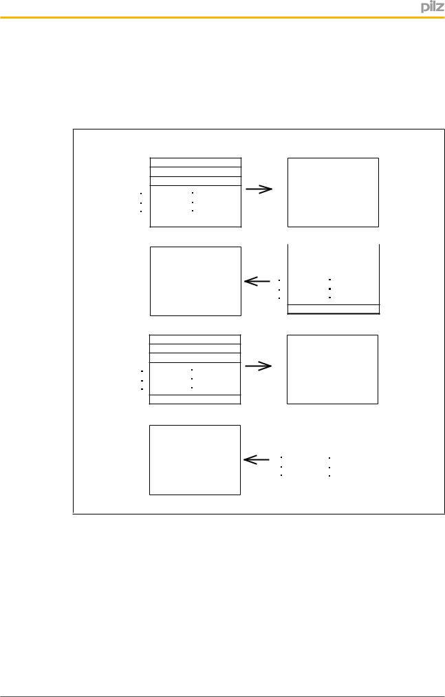
4.1.4.1Example 1 Access successful
Access to existing segments
The Master requests segment 1 from table 23. The fieldbus module confirms both these de tails and sends segment 1. Then the data from segment 5 table 21 is requested.
Master |
Fieldbus module |
1723
181
190
31 0
17 |
23 |
18 |
|
1 |
|
19 |
X |
|
|
31 X
1721
185
190
31 0
17 |
21 |
|
|
||
18 |
|
|
5 |
||
|
||
19 |
|
|
X |
||
|
||
31 |
|
|
|
||
X |
||
|
||
|
|
Operating Manual PNOZmulti 2 Communication Interfaces |
16 |
1002971EN02 |
|
Fieldbus Modules
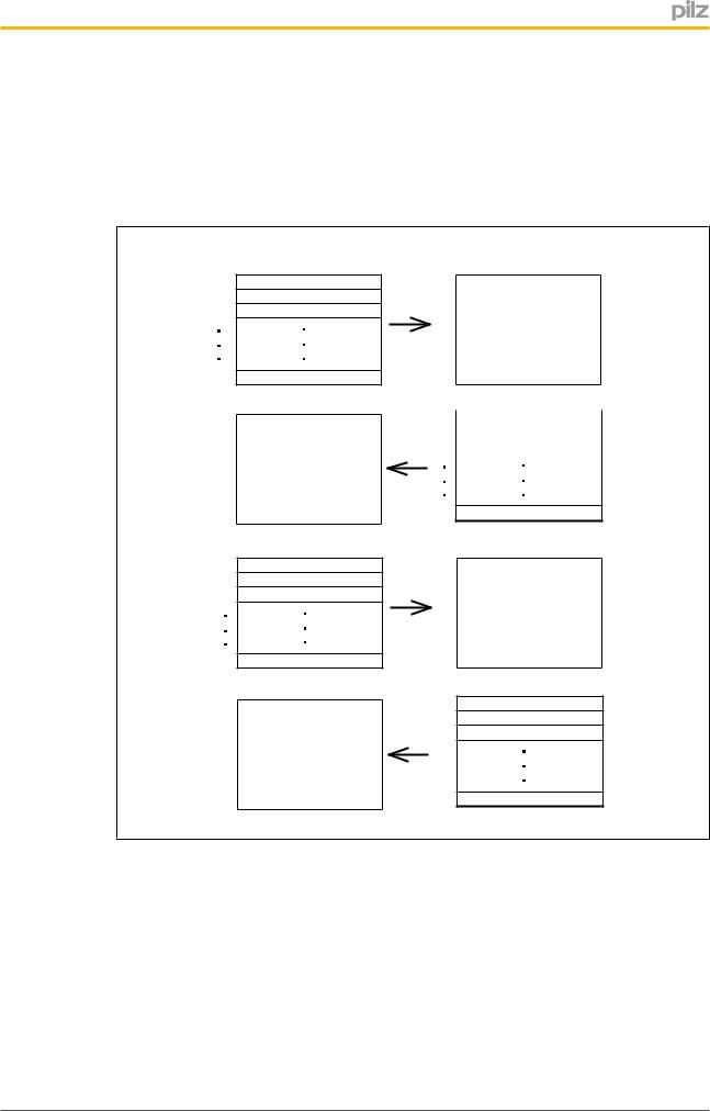
4.1.4.2Example 2 Access failed
Access to nonexistent segment
The Master requests segment 1 from table 23. The fieldbus module confirms both these de tails and sends segment 1. Then the Master requests segment 111 from table 23. As this table does not contain a segment 111, the Slave registers an error by sending back "255".
Master |
Fieldbus module |
1723
181
190
31 0
17 |
23 |
18 |
1 |
19 |
X |
|
|
31 X
1723
18111
190
31 0
23
255
X
X
Access to nonexistent table
The Master requests segment 1 from table 24. As there is no table 24, the Slave registers an error by sending back "255".
Operating Manual PNOZmulti 2 Communication Interfaces |
17 |
1002971EN02 |
|

Fieldbus Modules
Master |
Fieldbus module |
1724
181
190
31 0
17 |
24 |
18 |
|
255 |
|
19 |
|
X |
|
|
|
31 X
4.2PNOZ m ES Profibus
4.2.1Input and output data
Virtual inputs and outputs can be requested or set directly via the following objects. Each element can be selected individually in the master control system, e.g. virtual inputs i031. The data width is also established this way.
Input data
The Master writes to the virtual inputs of the PNOZmulti 2.
Description |
|
Input data from PNOZmulti 2 |
|
|
|
Virtual inputs i0 – i31 |
4 Input Bytes |
|
|
|
|
Virtual inputs i32 |
– i63 |
4 Input Bytes |
|
|
|
Virtual inputs i64 |
– i95 |
4 Input Bytes |
|
|
|
Virtual inputs i96 |
– i127 |
4 Input Bytes |
|
|
|
Output data
The Master reads the virtual outputs of the PNOZmulti 2.
Description |
|
Output data from PNOZmulti 2 |
|
|
|
Virtual outputs o0 – o31 |
4 Output Bytes |
|
|
|
|
Virtual outputs o32 |
– o63 |
4 Output Bytes |
|
|
|
Virtual outputs o64 |
– o95 |
4 Output Bytes |
|
|
|
Virtual outputs o96 |
– o127 |
4 Output Bytes |
|
|
|
Operating Manual PNOZmulti 2 Communication Interfaces |
18 |
1002971EN02 |
|

Fieldbus Modules
4.2.2Access to table segments
The data in the Tables [ 101] can be requested via the following objects.
Input data
The Master requests a table segment in the form:
Description |
Input data from PNOZmulti 2 |
|
|
Table and segment number |
2 Input Bytes |
|
|
Output data |
|
The PNOZmulti 2 replies in the form: |
|
|
|
Description |
Output data from PNOZmulti 2 |
|
|
Table and segment number + 13 Byte payload |
15 Output Bytes |
|
|
A detailed description is available in the chapter entitled Access to table segments [ 15].
15].
4.2.3LED status
The LED status of the PNOZmulti 2 can be requested directly via the following object.
Description |
Output data from PNOZmulti 2 |
|
|
LED status |
1 Output Byte |
|
|
}Bit 0 = 1: LED OFAULT is lit or flashes
}Bit 1 = 1: LED IFAULT is lit or flashes
}Bit 2 = 1: LED FAULT is lit or flashes
}Bit 3 = 1: LED DIAG is lit or flashes
}Bit 4 = 1: LED RUN is lit
}Bit 57: Reserved
4.2.4Diagnostic data PNOZ m ES Profibus
These bits contain the diagnostic data
Un |
Content |
it_Diag_Bit |
|
|
|
00 |
RUN, base unit is in RUN condition |
|
|
01 |
STOP, base unit is in STOP condition |
|
|
02 |
Base unit was stopped by the Configurator |
|
|
03 |
Reserved |
|
|
04 |
External error |
|
|
05 |
Internal error |
|
|
06 |
External error on the inputs |
|
|
Operating Manual PNOZmulti 2 Communication Interfaces |
19 |
1002971EN02 |
|

Fieldbus Modules
Un |
|
it_Diag_Bit Content |
|
07 |
Internal error on the inputs |
|
|
08 |
External error on the outputs |
09Internal error on the outputs
10No connection to base unit
11Reserved
…
21
22Error on the base unit
23Reserved
24Error on the 1st expansion module, right
25Error on the 2nd expansion module, right
26Error on the 3rd expansion module, right
27Error on the 4th expansion module, right
28Fault on the 5th expansion module, right
29Fault on the 6th expansion module, right
30Reserved
…
39
40Fault on 1st expansion module, left
41Fault on 2nd expansion module, left
42Fault on 3rd expansion module, left
43Fault on 4th expansion module, left
44Reserved
...
45
46Error on the communication module
47Reserved
…
55
56Error in the configuration, F_81
57Error in the application program, F_82
58Error in the periphery, F_83
59Error on the speed monitor, F_84
60Error on the bus module, F_85
61Error on the link module, F_86
62Error on the analogue input module, F_87
63Reserved
Operating Manual PNOZmulti 2 Communication Interfaces |
20 |
1002971EN02 |
|
Fieldbus Modules
Un
it_Diag_Bit Content
64Error on the input/output module, F_89
65Error on the Ethernet module, F_8A
66Internal error on the lefthand expansion module, F_90
67Internal periphery error, F_93
68Internal error on the righthand expansion module, F_94
69Internal error on the righthand expansion module, F_95
70Internal self test error, F_B0
71Internal data error, F_B1
72Internal parameter error, F_B2
73Internal serial/I2C error, F_B3
74Internal time error, F_B4
75Internal processor error, F_B5
76Internal parameter error, F_B6
77Internal compare error, F_B7
78Internal sequence error, F_B8
79Internal periphery error, F_B9
80Internal error on bus module, F_BA
81Internal error on link module, F_BB
82Internal error on speed monitor, F_BC
83Internal error on analogue input module, F_BD
84Internal error on link module, F_BE
85Internal error on link module, F_BF
86Internal error on the lefthand expansion module, F_C0
87Internal error on the lefthand expansion module, F_C1
88Internal error on the Ethernet module, F_C2
89Internal compare error, F_C3
90Internal error on the righthand expansion module, F_C4
91Internal error on the righthand expansion module, F_C5
92Reserved
…
95
}Explanation: Bits 56 to 91 display the last content of the error stack (corresponds to the error class). The bits are deleted as soon as PNOZmulti 2 returns to a RUN state.
Operating Manual PNOZmulti 2 Communication Interfaces |
21 |
1002971EN02 |
|

Fieldbus Modules
4.3PNOZ m ES CANopen
4.3.1Service Data Objects (SDOs)
All the relevant device parameters and current process data of the PNOZmulti 2 are entered in the object directory of the CANopen. These can be read and written via Service Data Objects (SDOs).
To enable the fieldbus module to be incorporated easily within a CANopen network, the ob ject directory is available as an EDS file (see Object directory, Service Data Objects (SDOs) [ 124].
124].
4.3.2Process Data Objects (PDOs)
The output data is stored as follows:
Byte |
Object Index |
Sub Index |
PDO |
COBID |
(hex) |
(hex) |
|||
|
|
|
|
|
0 |
2000 |
1 |
TPDO 1 |
180h |
|
|
|
|
+ node address |
1 |
2000 |
2 |
|
|
|
|
|
|
|
2 |
2000 |
3 |
|
|
|
|
|
|
|
3 |
2000 |
4 |
|
|
|
|
|
|
|
4 |
2000 |
5 |
|
|
|
|
|
|
|
5 |
2000 |
6 |
|
|
|
|
|
|
|
6 |
2000 |
7 |
|
|
|
|
|
|
|
7 |
2000 |
8 |
|
|
|
|
|
|
|
8 |
2000 |
9 |
TPDO 2 |
280h |
|
|
|
|
+ node address |
9 |
2000 |
A |
|
|
|
|
|
|
|
10 |
2000 |
B |
|
|
|
|
|
|
|
11 |
2000 |
C |
|
|
|
|
|
|
|
12 |
2000 |
D |
|
|
|
|
|
|
|
13 |
2000 |
E |
|
|
|
|
|
|
|
14 |
2000 |
F |
|
|
|
|
|
|
|
15 |
2000 |
10 |
|
|
|
|
|
|
|
16 |
2000 |
11 |
TPDO 3 |
380h |
|
|
|
|
+ node address |
17 |
2000 |
12 |
|
|
|
|
|
|
|
18 |
2000 |
13 |
|
|
|
|
|
|
|
19 |
2000 |
14 |
|
|
|
|
|
|
|
20 |
2000 |
15 |
|
|
|
|
|
|
|
21 |
2000 |
16 |
|
|
|
|
|
|
|
22 |
2000 |
17 |
|
|
|
|
|
|
|
23 |
2000 |
18 |
|
|
|
|
|
|
|
Operating Manual PNOZmulti 2 Communication Interfaces |
22 |
1002971EN02 |
|

Fieldbus Modules
Byte |
Object Index |
Sub Index |
PDO |
COBID |
(hex) |
(hex) |
|||
24 |
2000 |
19 |
TPDO 4 |
480h |
|
|
|
|
+ node address |
25 |
2000 |
1A |
|
|
|
|
|
|
|
26 |
2000 |
1B |
|
|
|
|
|
|
|
27 |
2000 |
1C |
|
|
|
|
|
|
|
28 |
2000 |
1D |
|
|
|
|
|
|
|
29 |
2000 |
1E |
|
|
|
|
|
|
|
30 |
2000 |
1F |
|
|
|
|
|
|
|
31 |
2000 |
20 |
|
|
|
|
|
|
|
The input data is stored as follows:
|
Byte |
Object Index |
Sub Index |
PDO |
COBID |
|
(hex) |
(hex) |
|||
|
|
|
|
|
|
|
0 |
2100 |
1 |
RPDO 1 |
200h |
|
|
|
|
|
+ node address |
|
1 |
2100 |
2 |
|
|
|
|
|
|
|
|
|
2 |
2100 |
3 |
|
|
|
|
|
|
|
|
|
3 |
2100 |
4 |
|
|
|
|
|
|
|
|
|
4 |
2100 |
5 |
|
|
|
|
|
|
|
|
|
5 |
2100 |
6 |
|
|
|
|
|
|
|
|
|
6 |
2100 |
7 |
|
|
|
|
|
|
|
|
|
7 |
2100 |
8 |
|
|
|
|
|
|
|
|
|
8 |
2100 |
9 |
RPDO 2 |
300h |
|
|
|
|
|
+ node address |
|
9 |
2100 |
A |
|
|
|
|
|
|
|
|
|
10 |
2100 |
B |
|
|
|
|
|
|
|
|
|
11 |
2100 |
C |
|
|
|
|
|
|
|
|
|
12 |
2100 |
D |
|
|
|
|
|
|
|
|
|
13 |
2100 |
E |
|
|
|
|
|
|
|
|
|
14 |
2100 |
F |
|
|
|
|
|
|
|
|
|
15 |
2100 |
10 |
|
|
|
|
|
|
|
|
|
16 |
2100 |
11 |
RPDO 3 |
400h |
|
|
|
|
|
+ node address |
|
17 |
2100 |
12 |
|
|
|
|
|
|
|
|
|
18 |
2100 |
13 |
|
|
|
|
|
|
|
|
|
19 |
2100 |
14 |
|
|
|
|
|
|
|
|
|
20 |
2100 |
15 |
|
|
|
|
|
|
|
|
|
21 |
2100 |
16 |
|
|
|
|
|
|
|
|
|
22 |
2100 |
17 |
|
|
|
|
|
|
|
|
|
23 |
2100 |
18 |
|
|
|
|
|
|
|
|
|
|
|
|
|
|
Operating Manual PNOZmulti 2 Communication Interfaces |
|
|
23 |
||
1002971EN02 |
|
|
|
|
|

Fieldbus Modules
Byte |
Object Index |
Sub Index |
PDO |
COBID |
(hex) |
(hex) |
|||
24 |
2100 |
19 |
RPDO 4 |
500h |
|
|
|
|
+ node address |
25 |
2100 |
1A |
|
|
|
|
|
|
|
26 |
2100 |
1B |
|
|
|
|
|
|
|
27 |
2100 |
1C |
|
|
|
|
|
|
|
28 |
2100 |
1D |
|
|
|
|
|
|
|
29 |
2100 |
1E |
|
|
|
|
|
|
|
30 |
2100 |
1F |
|
|
|
|
|
|
|
31 |
2100 |
20 |
|
|
|
|
|
|
|
Key to abbreviations:
TPDO: Transmit Process Data Object
RPDO: Receive Process Data Object
COBID: Communication Object Identifier
4.4PNOZ m ES EtherCAT
4.4.1Service Data Objects (SDOs)
All the relevant device parameters and current process data of the PNOZmulti 2 are entered in the object directory of the EtherCAT. These can be read and written via Service Data Objects (SDOs).
To enable the fieldbus module to be incorporated easily within a EtherCAT network, the ob ject directory is available as an EDS file (see Object directory, Service Data Objects (SDOs) [ 124].
124].
4.4.2Process Data Objects (PDOs)
The manufacturerspecific part of the object directory is structured as follows:
|
PDO (hex) |
Size |
Name |
Index (hex) |
SubIndex(hex) |
Content |
|
|
|
|
|
|
|
|
|
|
0x1A00 |
32 |
TxPDO |
2000 |
01 |
20 |
Output data (from the |
|
|
|
|
|
|
|
PNOZmulti) |
|
|
|
|
|
|
|
|
|
0x1A01 |
128 |
TxPDO |
2000 |
01 |
11 |
Default configuration |
|
|
|
|
|
|
|
(freely configurable) |
|
|
|
|
2001 |
01 |
08 |
|
|
|
|
|
|
|
|
|
|
|
|
|
2001 |
49 |
50 |
|
|
|
|
|
|
|
|
|
|
|
|
|
2002 |
01 |
08 |
|
|
|
|
|
|
|
|
|
|
|
|
|
2002 |
25 |
– 2C |
|
|
|
|
|
|
|
|
|
|
|
|
|
2002 |
49–50 |
|
|
|
|
|
|
|
|
|
|
|
|
|
|
2007 |
01–08 |
|
|
|
|
|
|
|
|
|
|
|
|
|
|
2007 |
25–2C |
|
|
|
|
|
|
|
|
|
|
|
|
|
|
2007 |
49–50 |
|
|
|
|
|
|
|
|
|
|
|
|
|
|
200A |
01–2E |
|
|
|
|
|
|
|
|
|
|
|
|
|
|
|
|
|
|
|
Operating Manual PNOZmulti 2 Communication Interfaces |
|
|
24 |
|||
|
1002971EN02 |
|
|
|
|
|
|

Fieldbus Modules
PDO (hex) |
Size |
Name |
Index (hex) |
SubIndex(hex) |
Content |
0x1600 |
19 |
RxPDO |
2100 |
0113 |
Input data (to the PNOZmulti) |
|
|
|
|
|
|
Key to abbreviations:
TxPDO: Transmit Process Data Object
RxPDO: Receive Process Data Object
4.5PNOZ m ES Powerlink
4.5.1Service Data Objects (SDOs)
All the relevant device parameters and current process data of the PNOZmulti 2 are entered in the object directory of the Ethernet POWERLINK. These can be read and written via Service Data Objects (SDOs).
To enable the fieldbus module to be incorporated easily within a Ethernet POWERLINK network, the object directory is available as an EDS file (see Object directory, Service Data Objects (SDOs) [ 124].
124].
4.5.2Process Data Objects (PDOs)
A PDO can be assembled individually from the SDOs.
Maximum size for the PDOs:
}254 Bytes input data
}32 Bytes output data
The inputs and outputs are viewed from the Managing Node.
Operating Manual PNOZmulti 2 Communication Interfaces |
25 |
1002971EN02 |
|

Communication modules
5 |
Communication modules |
5.1Overview
The communication module on the configurable control system PNOZmulti 2 is used to
}Download and upload the project,
}Read the diagnostic words,
}Read the error stack.
The following combinations are possible:
}Serial interface RS232
–Base unit PNOZ m B0 + PNOZ m ES RS232
}Ethernet interfaces
–Base unit PNOZ m B0 + PNOZ m ES ETH
5.2PNOZ m ES RS232
The connection to the RS 232 interface of the communication partner and the communica tion module PNOZ m ES RS232 is established via a null modem cable.
Transmission rate:
19.2 kBit with
}8 bits of data
}1 start bit
}2 stop bits
}1 parity bit
}Even parity
5.3PNOZ m ES ETH
5.3.1Introduction
This chapter describes the special features of communication with the expansion module PNOZ m ES ETH via Ethernet and Modbus/TCP. Access to data from the PNOZmulti 2 via tables and segments is described in Chapter Basics [ 13].
13].
5.3.2Overview
The expansion module PNOZ m ES ETH provides an interface to Ethernet. Via this inter face, the configurable control system PNOZmulti 2 can be connected via Ethernet to control systems that support Modbus/TCP. Modbus/TCP is designed for fast data exchange at field level. The expansion module PNOZ m ES ETH is a passive Modbus/TCP subscriber (Server). The basic functions of communication with Ethernet or Modbus/TCP conform to IEEE 802.3. The central controller (Client) reads output information from the Servers and writes input information to the Servers as part of each cycle. In addition to the cyclical pay load transmission, the PNOZ m ES ETH also has diagnostic functions.
The connections are established via two RJ45 sockets.
Operating Manual PNOZmulti 2 Communication Interfaces |
26 |
1002971EN02 |
|

Communication modules
The Ethernet interface is configured in the PNOZmulti Configurator (for description see on line help for the PNOZmulti Configurator).
The communication module PNOZ m ES ETH supports Modbus/TCP [ 45].
45].
The module can manage up to 8 Modbus/TCP connections and up to 4 PG port (Port 9000) connections.
5.3.3Module features
}Can be configured in the PNOZmulti Configurator
}Network protocols: TCP/IP, Modbus/TCP
}Status indicators for communication and for errors
}Transmission rate 10 MBit/s (10BaseT) and 100 MBit/s (100BaseTX), full and half du plex
5.3.4Modbus/TCP
There is no need to configure a connection on the PNOZ m ES ETH. Port 502 is used in accordance with the Modbus/TCP specification.
For details of Modbus/TCP Modbus/TCP [ 45]
45]
5.3.5RJ45 interfaces ("Ethernet")
Two free switch ports are provided as Ethernet interfaces via an internal autosensing switch. The autosensing switch automatically detects whether data transfer is occurring at 10 Mbit/s or 100 Mbit/s.
INFORMATION
The connected subscribers must support the autosensing/autonegotiation function. If not, the communication partner must be set permanently to "10 Mbit/s, half duplex".
The switch's automatic crossover function means there is no need to distinguish on the connection cable between patch cable (uncrossed data line connection) and crossover cable (crossover data line connection). The switch automatically creates the correct data line connection internally. Patch cable can therefore be used as the connection cable for end devices as well as cascading.
Both Ethernet interfaces use RJ45 technology.
5.3.6Requirements of the connection cable and connector
The following minimum requirements must be met:
}Ethernet standards (min. Category 5) 10BaseT or 100BaseTX
}Doubleshielded twisted pair cable for industrial Ethernet use
}Shielded RJ45 connectors (industrial connectors)
Operating Manual PNOZmulti 2 Communication Interfaces |
27 |
1002971EN02 |
|
Communication modules
5.3.7Interface configuration
RJ45 socket |
|
|
|
|
|
|
|
|
|
|
|
|
|
|
|
|
|
||||
8pin |
|
|
|
|
|
|
|
|
|
|
|
|
|
|
PIN |
Standard |
Crossover |
||||
|
|
|
|
|
|
|
|
|
|
|
|
|
|
|
|
|
|
|
|
|
|
|
|
|
|
|
|
|
|
|
|
|
|
|
|
|
|
|
|
|
1 |
TD+ (Transmit+) |
RD+ (Receive+) |
|
|
|
|
|
|
|
|
|
|
|
|
|
|
|
|
|
|
|
|||
|
|
|
|
|
|
|
|
|
|
|
|
|
|
|
|
|
|
|
|||
|
|
|
|
|
|
|
|
|
|
|
|
|
|
|
|
|
|
|
|
|
|
|
|
|
|
|
|
|
|
|
|
|
|
|
|
|
|
|
|
|
2 |
TD (Transmit) |
RD (Receive) |
|
|
|
|
|
|
|
|
|
|
|
|
|
|
|
|
|
|
|
|||
|
|
|
|
|
|
|
|
|
|
|
|
|
|
|
|
|
|
|
|||
|
|
|
|
|
|
|
|
|
|
|
|
|
|
|
|
|
|
|
|
|
|
|
|
|
|
|
|
|
|
|
|
|
|
|
|
|
|
|
|
|
3 |
RD+ (Receive+) |
TD+ (Transmit+) |
|
|
|
|
|
|
|
|
|
|
|
|
|
|
|
|
|
|
|
|||
|
|
|
|
|
|
|
|
|
|
|
|
|
|
|
|
|
|
|
|||
8 |
|
|
1 |
|
|
|
|
|
|||||||||||||
|
|
|
|
4 |
n.c. |
n.c. |
|||||||||||||||
|
|
|
|
|
|
|
|
|
|
|
|
|
|
|
|
|
|
|
|||
|
|
|
|
|
|
|
|
|
|
|
|
|
|
|
|
|
|
|
|
|
|
|
|
|
|
|
|
|
|
|
|
|
|
|
|
|
|
|
|
|
5 |
n.c. |
n.c. |
|
|
|
|
|
|
|
|
|
|
|
|
|
|
|
|
|
|
|
|
|
|
|
|
|
|
|
|
|
|
|
|
|
|
|
|
|
|
|
|
|
6 |
RD (Receive) |
TD (Transmit) |
|
|
|
|
|
|
|
|
|
|
|
|
|
|
|
|
|
|
|
|
|
|
|
|
|
|
|
|
|
|
|
|
|
|
|
|
|
|
|
|
|
7 |
n.c. |
n.c. |
|
|
|
|
|
|
|
|
|
|
|
|
|
|
|
|
|
|
|
|
|
|
|
|
|
|
|
|
|
|
|
|
|
|
|
|
|
|
|
|
|
8 |
n.c. |
n.c. |
|
|
|
|
|
|
|
|
|
|
|
|
|
|
|
|
|
|
|
|
|
|
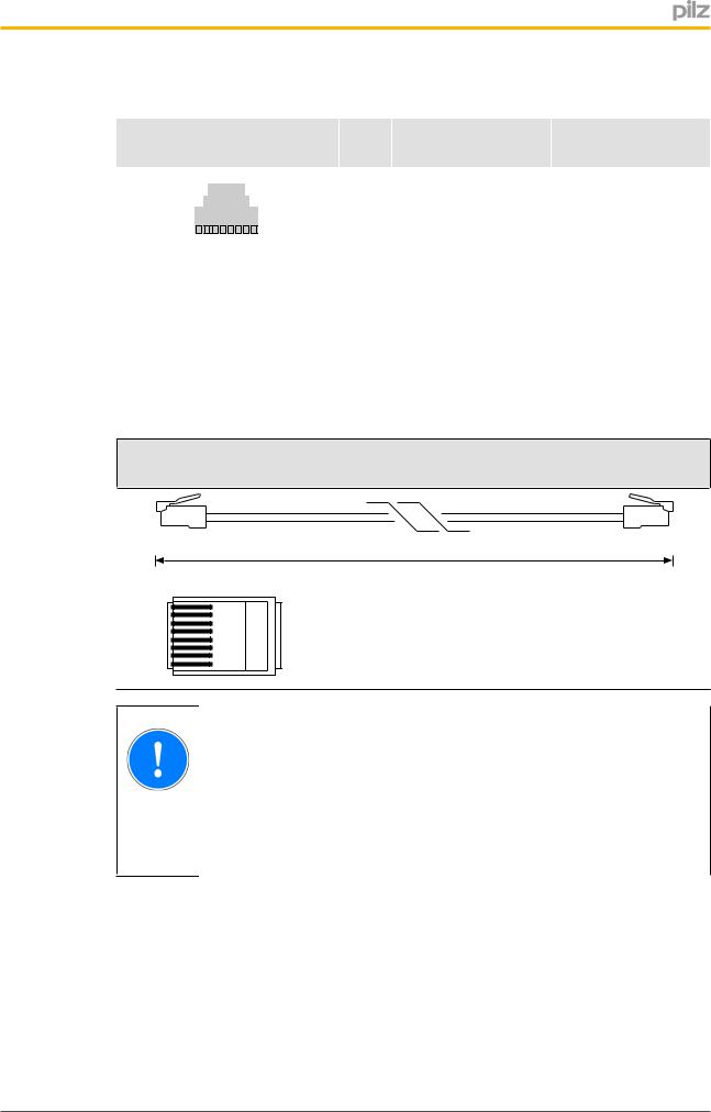
5.3.8RJ45 connection cable
RJ45 connector |
8pin |
10BaseT cable or 100BaseTX cable |
max. 100 m |
8 |
1 |
NOTICE |
With the plugin connection please note that the data cable and connector have a limited mechanical load capacity. Appropriate design measures should be used to ensure that the plugin connection is insensitive to in creased mechanical stress (e.g. through shock, vibration). Such measures include fixed routing with strain relief, for example.
5.3.9Process data exchange
The RJ45 interfaces on the internal autosensing switch enable process data to be ex changed with other Ethernet subscribers within a network.
The PNOZ m ES ETH can also be connected to Ethernet via a hub (hub or switch).
Operating Manual PNOZmulti 2 Communication Interfaces |
28 |
1002971EN02 |
|

Communication modules
|
Ethernet |
Hub/Switch |
Hub/Switch |
Ethernet subscriber |
Ethernet subscriber |
|
PC with PNOZmulti |
PNOZ m B0 + |
Configurator |
|
|
PNOZ m ES ETH |
|
|
PNOZ m B0 + |
|
PNOZ m ES ETH |
Fig.: PNOZmulti 2 as Ethernet subscriber possible topologies
5.4Communication procedure
The PNOZmulti 2 is always the connection's Server in the communication; the communica tion partner (PC, SPS) is the Client.
INFORMATION
For communication via Ethernet, the Ethernet interface must be set up in the PNOZmulti Configurator. The procedure is described in the PNOZmulti Configurator's online help.
Each communication is started by sending a request to the PNOZmulti 2. Requests are used to receive data from the PNOZmulti 2 or send data to the PNOZmulti 2 :
1. Request:
The user sends a request to the PNOZmulti 2 via the communications partner.
Operating Manual PNOZmulti 2 Communication Interfaces |
29 |
1002971EN02 |
|

Communication modules
2. Response:
The PNOZmulti 2 sends a response to the communications partner after approx. 20 to 30 ms, confirming that the request has been received without error. Data is sent in accordance with the request.
5.5Telegram structure
The telegram used for communication consists of:
}a header,
}the payload,
}a footer.
Telegram |
Byte |
Request |
|
Byte |
Response |
section |
|
|
|
|
|
|
0 |
0x05 |
|
0 |
0x05 |
|
|
|
|
|
|
|
1 |
0x15 |
|
1 |
0x15 |
|
|
|
|
|
|
Header |
2 |
0x00 |
|
2 |
0x00 |
|
|
|
|
|
|
3 |
Payload amount +5 |
|
3 |
Payload amount +5 |
|
|
|
||||
|
|
|
|
|
|
|
4 |
Request No. |
|
4 |
Confirmation/error |
|
|
|
|
|
|
|
5 |
Segment No. HB |
|
5 |
Segment No. HB |
|
|
|
|
|
|
|
6 |
Segment No. LB |
|
6 |
Segment No. LB |
|
|
|
|
|
|
|
7 |
0x00 |
|
7 |
Reserved |
|
|
|
|
|
|
|
8 |
Payload Byte 0 |
|
8 |
Payload Byte 0 |
|
|
|
|
|
|
|
9 |
Payload Byte 1 |
|
9 |
Payload Byte 1 |
|
|
|
|
|
|
Payload |
10 |
Payload Byte 2 |
|
10 |
Payload Byte 2 |
|
|
|
|
|
|
... |
... |
|
... |
... |
|
|
|
||||
|
|
|
|
|
|
|
Payload |
Payload Byte n |
|
Payload |
Payload Byte n |
|
amount +7 |
|
|
amount +7 |
|
|
Payload |
BCC |
|
Payload |
BCC |
|
amount +8 |
|
|
amount +8 |
|
|
|
|
|
|
|
Footer |
Payload |
0x10 |
|
Payload |
0x10 |
|
amount +9 |
|
|
amount +9 |
|
5.5.1 |
Header |
|
Byte 0 ... Byte 7 form the data block's header |
}Byte 0: Always 0x05
}Byte 1: Always 0x15
}Byte 2: Always 0x00
}Byte 3: Payload amount plus 5
}Byte 4
–Request: Request number
A request is defined via the request number Requests [ 33]
33]
Operating Manual PNOZmulti 2 Communication Interfaces |
30 |
1002971EN02 |
|
Loading...