


PSS SB TESTER D
Table of contents
 Loading...
Programmable Safety Systems
PSS-Range
PSS SB TESTER
Operating Manual
Item No. 20 757-03
The spirit of safety.

All rights to this manual are reserved by Pilz GmbH & Co. Copies may be made for internal
purposes.
While every effort has been made to ensure that the information in this manual is accurate,
no responsibility can be accepted for errors or omissions contained within it.
We reserve the right to amend specifications without notice. We are grateful for any
feedback on the contents of this manual.
The names of products, goods and technologies used in this manual are trademarks of the
respective companies.

Contents
Introduction 1-1
Validity of documentation 1-1
Overview of documentation 1-1
Definition of symbols 1-2
Overview 2-1
Range 2-1
Safety 3-1
Intended use 3-1
EMCD 3-1
Warranty and liability 3-1
Disposal 3-2
Operation 4-1
Supply 4-1
Charging the battery 4-1
Commissioning 4-2
Switching on 4-2
Setting the contrast 4-3
Switching the backlight on/off 4-3
Setting the time and date 4-4
Setting the signal runtime 4-5
Calibration 4-5
Performing the tests 4-6
Saving the test results 4-6
Uploading the test results to a PC 4-7
Deleting the test results 4-7
Operating Manual: PSS SB TESTER 1

Contents
Tests/Measurements 5-1
Connection test 5-2
Performing the connection test 5-2
Separate test: Resistance between CAN_H and CAN_L 5-4
Separate tests: Short circuits between the bus cable wires 5-5
Screening test 5-6
Performing the screening test 5-6
Length measurement 5-9
Performing the length measurement 5-13
Signal test 5-16
Performing the signal test 5-16
Separate test: Measuring the voltage at Vcc 5-17
Separate test: Testing the transmission rate 5-18
Separate tests: Testing the electrical signal level 5-19
Separate tests: Testing the signal edges 5-20
Real-time mode 5-21
Performing the real-time measurement 5-21
Software 6-1
System requirements 6-1
Installation 6-1
Starting the software 6-1
Fault Diagnostics 7-1
Technical Details 8-1
2 Operating Manual: PSS SB TESTER

Introduction
This operating manual is intended to give users all the information they
need to use the PSS SB TESTER.
To fully understand this manual you will need to be conversant with the
information found in the general documentation for the SafetyBUS p PSSrange. In particular you should read the SafetyBUS p System Description
and SafetyBUS p Installation Manual.
This documentation is intended for instruction and should be retained for
future reference.
Validity of documentation
This documentation is valid for the PSS SB TESTER from Version 2.0.
It is valid until new documentation is published. The latest documentation is
always enclosed with the unit.
Overview of documentation
The manual is divided into the following chapters:
1 Introduction
The introduction is designed to familiarise you with the contents,
structure and specific order of this manual.
2 Overview
This chapter provides a brief overview of the unit’s most important
features and its application range.
3 Safety
This chapter must be read as it contains important information on
safety regulations and intended use.
4 Operation
This chapter contains detailed information on how to operate the unit.
5 Tests/Measurements
This chapter describes the separate tests than can be performed
using the PSS SB TESTER.
6 Software
This chapter describes the software used to read the test results.
Operating Manual: PSS SB TESTER 1-1
Introduction
7 Fault Diagnostics
When a fault is detected on SafetyBUS p, this chapter helps you find
the source of the fault and rectify it.
8 Technical Details
Definition of symbols
Information in this manual that is of particular importance can be identified
as follows:
DANGER!
This warning must be heeded! It warns of a hazardous situation that
poses an immediate threat of serious injury and death and indicates
preventive measures that can be taken.
WARNING!
This warning must be heeded! It warns of a hazardous situation that
could lead to serious injury and death and indicates preventive
measures that can be taken.
CAUTION!
This refers to a hazard that can lead to a less serious or minor injury plus
material damage, and also provides information on preventive measures
that can be taken.
NOTICE
This describes a situation in which the unit(s) could be damaged and also
provides information on preventive measures that can be taken.
INFORMATION
This gives advice on applications and provides information on special
features, as well as highlighting areas within the text that are of particular
importance.
1-2 Operating Manual: PSS SB TESTER

Overview
The PSS SB TESTER is a hand-held device that can be used to carry out
various tests and measurements on SafetyBUS p. Each test may comprise
several separate tests.
• Connection test
- Checks the terminating resistors
- Checks the bus cable wires for short circuits
• Screening test
- Checks the cable screening for open circuits
• Length measurement
- Measures the length of the bus line
- Determines the location of a short circuit between CAN_H and CAN_L
• Signal test
- Tests the transmission rate
- Tests the electrical signal level on the lines CAN_H and CAN_L
- Tests the signal edges on the lines CAN_H and CAN_L
Range
• Real-time mode
- Measures the bus load
- Measures error rate, failure rate and number of errors
Once a test has been completed, the results can be read directly from the
device’s display or can be uploaded to a PC using the software provided.
The PSS SB TESTER is supplied in a carry case. Items supplied are as
follows:
• PSS SB TESTER incl. battery
• Shorting plug for the screening test
• Adapter cable for connecting the PSS SB TESTER to SafetyBUS p
• USB cable for connecting the PSS SB TESTER to a PC
• Battery charger
• Operating Manual: PSS SB TESTER
• CD:
- Software for recording the test results on a PC
- Operating manual in PDF format
- Acrobat Reader
Operating Manual: PSS SB TESTER 2-1
Overview
1
2
F2F1 F3
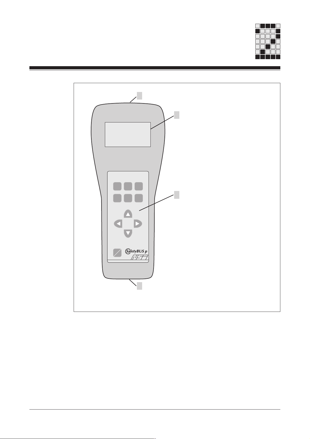
Fig. 2-1: View
ON
OFF
HLPESC VAL
4
3
1: SafetyBUS p interface
2: Single-colour graphic display
with backlight
3: Operator panel
4: USB port for uploading the test
results to a PC
2-2 Operating Manual: PSS SB TESTER

Safety
Intended use
The PSS SB TESTER is designed for use in SafetyBUS p networks.
Specific data for the PSS SB TESTER is given in the chapter entitled
“Technical Details”. Use of the device outside the specifications given here
will be deemed as improper use.
Any component, technical or electrical modifications carried out will be
deemed as improper use.
Use of the PSS SB TESTER outside the areas described in this manual
will be deemed as improper use.
Intended use includes following the information in this manual.
The PSS SB TESTER is not a safety-related device.
EMCD
The device is designed for use in an industrial environment. Interference
may occur if used within a domestic environment.
Warranty and liability
All claims to warranty and liability will be rendered invalid if
• The module was used contrary to the purpose for which it was intended
• Damage can be attributed to not having followed the guidelines in the
manual
• Operating personnel are not suitably qualified.
• The housing was opened
• Any type of modification has been made (e.g. exchanging components
on the PCB boards, soldering work etc.).
Operating Manual: PSS SB TESTER
3-1

Safety
Disposal
The module must be disposed of properly when it reaches the end of its
service life.
3-2 Operating Manual: PSS SB TESTER

Operation
Supply
The PSS SB TESTER is supplied via a battery, which is located in the
back of the housing.
A charged PSS SB TESTER can be operated for 1 to 2 hours, depending
on the application conditions. If the battery charge drops to a particular
value during testing, the message “Charge battery” will be displayed and a
beep will sound. If the battery charge becomes so weak that the supply
can no longer be guaranteed, the PSS SB TESTER will switch off
automatically. The battery will need to be recharged. This takes approx. 1.5
hours.
INFORMATION
When the PSS SB TESTER is used for the first time or after storage
periods of more than 6 months, the battery will need to be charged for at
least 4 hours.
Charging the battery
• Plug the charger’s mains connector into a socket (110/230 VAC, 50 Hz).
• Take the PSS SB TESTER battery and plug it into the charger. The
charger is designed in such a way that the battery can only be inserted at
the correct polarity.
The start of the charging process is displayed via a red LED on the
charger’s connector (100 % on).
When the main charge is complete, the charger automatically switches to
“Conservation charging” mode and the LED flashes (25 % on, 75 % off).
If the main charge cannot be completed within 2 ½ hours, the charger
automatically switches to “Conservation charging” mode.
If the battery is extremely depleted, the LED will flash (50 % on, 50 % off)
when the battery is plugged into the charger. The battery is then charged
with a reduced charging current until the battery is regenerated and can be
switched to “normal” main charge mode.
Operating Manual: PSS SB TESTER 4-1

Operation
INFORMATION
The battery should not be left in the charger over a long period of time
(several weeks).
• Charge the battery until the LED on the charger flashes (25 % on, 75 %
off)
• Remove the battery and place in the PSS SB TESTER.
Commissioning
Switching on
INFORMATION
Before the PSS SB TESTER is used for the first time, the battery must be
charged for at least 4 hours.
The PSS SB TESTER is switched on via the “ON/OFF” button.
When it is switched on, the unit description “PSS SB TESTER” and its
version is displayed briefly.
The “Start” window then appears. From this window you can access
various menus.
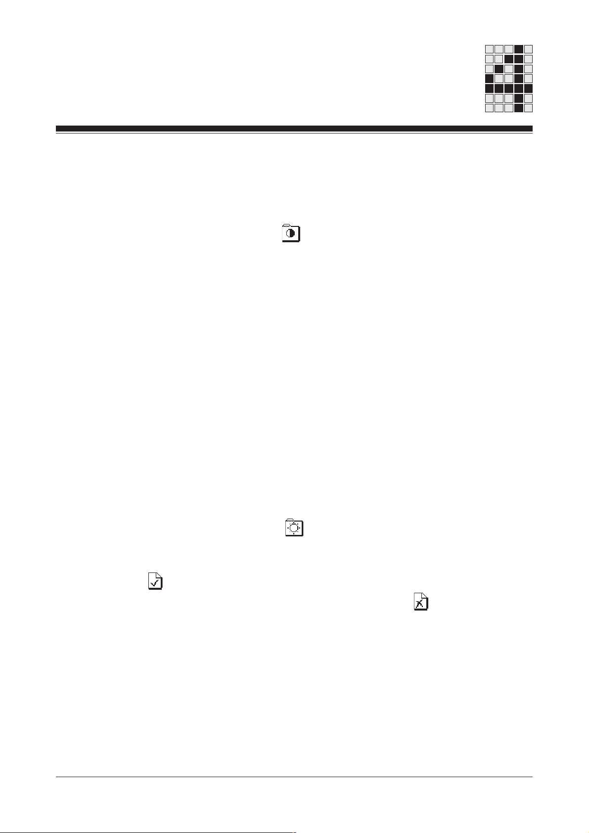
Key to the symbols and function of the buttons in the “Start” window:
: Select test/measurement
: Set transmission rate
F1: Display unit version
F2: Make one of the following settings:
- Set the contrast
- Switch the backlight on/off
- Set the time and date
- Set the signal runtime
- Calibration
F3: Save or delete test results
HLP: Call up help
ESC: Cancel function/close window
VAL: Carry out function
4-2 Operating Manual: PSS SB TESTER
Setting the contrast
• Press F2 in the “Start” window.
• The “Settings” window opens. Use the arrow keys to move the cursor to
the symbol for “Contrast” and press VAL.
• Now you can use the “left” and “right” arrow keys to increase or reduce
the display’s contrast.
• Press VAL to save the setting.
The current setting is saved. A message confirms that the setting has been
saved. The “Settings” window is then displayed again. You can return to
the “Start” window by pressing ESC.
The contrast setting is stored in a memory that is supplied by the battery. If
the battery is removed, the contents of the memory will be retained for 10
minutes. If it takes longer for the battery to be replaced, the contents of the
memory will be lost.
Switching the backlight on/off
• Press F2 in the “Start” window.
• The “Settings” window opens. Use the arrow keys to move the cursor to
the symbol for “Backlight” and press VAL.
• Two symbols will appear.
If you wish to switch the backlight on, use the arrow keys to highlight the
symbol.
If you wish to switch the backlight off, highlight the symbol.
• Press VAL to save the setting.
The current setting is saved. A message confirms that the setting has been
saved. The “Settings” window is then displayed again. You can return to
the “Start” window by pressing ESC.
Operating Manual: PSS SB TESTER 4-3

Operation
The information on the backlight is stored in a memory that is supplied by
the battery. If the battery is removed, the contents of the memory will be
retained for 10 minutes. If it takes longer for the battery to be replaced, the
contents of the memory will be lost.
Setting the time and date
• Press F2 in the “Start” window.
• The “Settings” window opens. Use the arrow keys to move the cursor to
the symbol for “Time and Date” and press VAL.
• The time and date are displayed. The ex-works setting is 01.01.2000 for
the date and 00:00 for the time.
The weekday is highlighted within a grey field. Use the “up” and “down”
arrow keys to set the required weekday.
You can then use the “right” arrow key to move the grey field to the
month; set the required month using the “up” and “down” arrow keys. Do
the same for the year, hour and minute.
• Press VAL to save the setting.
The current setting is saved. A message confirms that the setting has been
saved. The “Settings” window is then displayed again. You can return to
the “Start” window by pressing ESC.
The setting is stored in a memory that is supplied by the battery. If the
battery is removed, the contents of the memory will be retained for 10
minutes. If it takes longer for the battery to be replaced, the contents of the
memory will be lost.
4-4 Operating Manual: PSS SB TESTER

Setting the signal runtime
To measure the length of the bus cable you will need to enter the signal
runtime. The ex-works setting for the signal runtime is 4.5 ns/m. This value
is valid for the Pilz standard cable for SafetyBUS p (order no. 311 070). If
you use a cable with a different signal runtime, you will need to amend the
set value.
• Press F2 in the “Start” window.
• The “Settings” window opens. Use the arrow keys to move the cursor to
the symbol for “Signal runtime” and press VAL.
• Use the arrow keys to enter the password “7041” and press VAL.
• The signal runtime is displayed. Use the arrow keys to set the signal
runtime to the required value.
• Press VAL to save the setting.
The current setting is saved. A message confirms that the setting has been
saved. The “Settings” window is then displayed again. You can return to
the “Start” window by pressing ESC.
Calibration
The setting is stored in a memory that is supplied by the battery. If the
battery is removed, the contents of the memory will be retained for 10
minutes. If it takes longer for the battery to be replaced, the contents of the
memory will be lost.
Calibration is reserved for Pilz customer service.
Operating Manual: PSS SB TESTER 4-5
Loading...