


SGS Thomson Microelectronics ST232CWR, ST232BDR, ST232BWR, ST232BW, ST232BTR Datasheet
...
|
ST232 |
|
5V POWERED MULTI-CHANNEL |
|
RS-232 DRIVERS AND RECEIVERS |
■SUPPLY VOLTAGE RANGE: 4.5 TO 5.5V
■SUPPLY CURRENT NO LOAD (TYP): 5mA
■TRANSMITTER OUTPUT VOLTAGESWING (TYP): ±7.8V
■CONTROLLED OUTPUT SLEW RATE
■RECEIVER INPUT VOLTAGE RANGE: ±30V
■DATA RATE (TYP): 220Kbps
■OPERATING TEMPERATURE RANGE: -40 TO 85 oC, 0 TO 70 oC
■COMPATIBLE WITH MAX232 AND MAX202
DESCRIPTION
The ST232 is a 2 driver, 2 receiver device following EIA/TIA-232 and V.28 communication standard. It is particularly suitable for applications where ±12V is not available. The ST232 uses a single 5V power supply and only four external capacitors (0.1μF). Typical applications are in: Portable Computers, Low Power Modems, Interfaces Translation, Battery Powered RS-232 System, Multi-Drop RS-232 Networks.
ORDER CODES
N |
D |
(Plastic Package) |
(Micro Package) |
W |
T |
(Micro Package Large) |
(TSSOP Package) |
Type |
T emperature |
Packag e |
Comments |
|
Ran ge |
|
|
ST232CN |
0 to 70 oC |
DIP-16 |
25 parts per tube / 40 tube per box |
ST232BN |
-40 to 85 oC |
DIP-16 |
25 parts per tube / 40 tube per box |
ST232CD |
0 to 70 oC |
SO-16 (Tube) |
50 parts per tube / 20 tube per box |
ST232BD |
-40 to 85 oC |
SO-16 (Tube) |
50 parts per tube / 20 tube per box |
ST232CDR |
0 to 70 oC |
SO-16 (Tape & Reel) |
2500 parts per reel |
ST232BDR |
-40 to 85 oC |
SO-16 (Tape & Reel) |
2500 parts per reel |
ST232CW |
0 to 70 oC |
SO-16 Large (Tube) |
49 parts per tube / 25 tube per box |
ST232BW |
-40 to 85 oC |
SO-16 Large (Tube) |
49 parts per tube / 25 tube per box |
ST232CWR |
0 to 70 oC |
SO-16 Large (Tape & Reel) |
1000 parts per reel |
ST232BWR |
-40 to 85 oC |
SO-16 Large (Tape & Reel) |
1000 parts per reel |
ST232CT |
0 to 70 oC |
TSSOP16 (Tube) |
only for samples |
ST232BT |
-40 to 85 oC |
TSSOP16 (Tube) |
only for samples |
ST232CTR |
0 to 70 oC |
TSSOP16 (Tape & Reel) |
2500 parts per reel |
ST232BTR |
-40 to 85 oC |
TSSOP16 (Tape & Reel) |
2500 parts per reel |
February 2001 |
1/11 |

ST232
PIN CONFIGURATION
PIN DESCRIPTION
PIN No |
SYMBOL |
NAME AND F UNCTION |
1 |
C1+ |
Positive Terminal for the first Charge Pump Capacitor |
2 |
V+ |
Doubled Voltage Terminal |
3 |
C1- |
Negative Terminal for the first Charge Pump Capacitor |
4 |
C2+ |
Positive Terminal for the second Charge Pump Capacitor |
5 |
C2- |
Negative Terminal for the second Charge Pump Capacitor |
6 |
V- |
Inverted Voltage Terminal |
7 |
T2OUT |
Second Transmitter Output Voltage |
8 |
R2IN |
Second Receiver Input Voltage |
9 |
R2OUT |
Second Receiver Output Voltage |
10 |
T2IN |
Second Transmitter Input Voltage |
11 |
T1IN |
First Transmitter Input Voltage |
12 |
R1OUT |
First Receiver Output Voltage |
13 |
R1IN |
First Receiver Input Voltage |
14 |
T1OUT |
First Transmitter Output Voltage |
15 |
GND |
Ground |
16 |
VCC |
Supply Voltage |
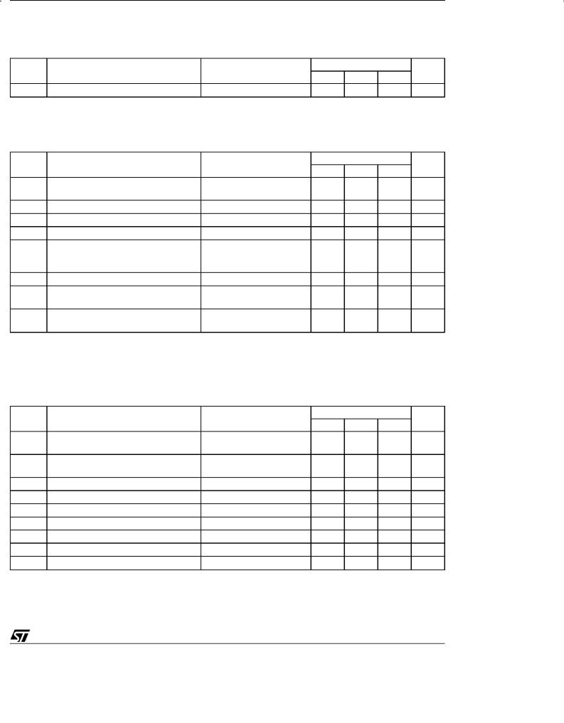
ABSOLUTE MAXIMUM RATINGS (Note 1)
Symbol |
Parameter |
Val ue |
Unit |
VCC |
Supply Voltage |
-0.3 to 6 |
V |
TIN |
Transmitter Input Voltage Range |
-0.3 to (VCC + 0.3) |
V |
RIN |
Receiver Input Voltage Range |
±30 |
V |
TOUT |
Transmitter Output Voltage Range |
(V+ + 0.3) to (V- - 0.3) |
V |
ROUT |
Receiver Output Voltage Range |
-0.3 to (VCC + 0.3) |
V |
TSCTOUT |
Short Circuit Duration on TOUT |
infinite |
|
Tstg |
Storage Temperature Range |
-65 to +150 |
oC |
Absolute Maximum Ratings are those values beyond which damage to the device may occur. Functional operation under these condition is not implied. Note1: No external supply can be applied toV+ terminal and V- terminal.
2/11
ST232
ELECTRICAL CHARACTERISTICS
(C1 -C4 = 0.1μF, VCC = 5V ± 10% TA = -40 to 85 oC, unless otherwise specified. Typical Valus are referred to TA = 25 oC)
Symb ol |
Parameter |
T est Cond it ion s |
Value |
|
Un it |
|
|
|
Min. T yp. Max. |
|
|
ISUPPLY |
VCC Power Supply Current |
No Load, TA = 25 oC |
5 |
10 |
mA |
TRANSMITTER ELECTRICAL CHARACTERISTICS
(C1 -C4 = 0.1μF, VCC = 5V ± 10%, TA = -40 to 85 oC, unless otherwise specified. Typical Valus are referred to TA = 25 oC)
Symb ol |
Parameter |
T est Cond it ion s |
|
Value |
|
Un it |
|
|
|
Min. T yp. Max. |
|
||
VTOUT |
Output Voltage Swing |
All Transmitter outputs are |
±5 |
±7.8 |
|
V |
|
|
loaded with 3KΩ to GND |
|
|
|
|
ITIL |
Logic Pull-Up Current |
TIN = 0 V |
|
15 |
200 |
μA |
VTIL |
Input Logic Threshold Low |
|
|
|
0.8 |
V |
VTIH |
Input Logic Threshold High |
|
2 |
|
|
V |
SRT |
Transition Slew Rate |
TA = 25 oC, VCC = 5 V, |
|
7 |
30 |
V/μs |
|
|
RL = 3 to 7 KΩ, |
|
|
|
|
|
|
CL= 50 to 2500 pF (Note 1) |
|
|
|
|
DR |
Data Rate |
(Note 2) |
120 |
220 |
|
Kbits/s |
RTOUT |
Transmitter Output Resistance |
VCC = V+ = V- = 0V |
300 |
|
|
Ω |
|
|
VOUT = ± 2 V |
|
|
|
|
ISC |
Transmitter Output Short Circuit |
one TXOUT to GND |
|
±10 |
±60 |
mA |
|
Current |
|
|
|
|
|
Note 1: Measured from 3V to -3Vor from -3V to 3V.
Note 2: One trasmitter output is loaded with RL = 3KΩ to7KΩ, CL = 50to 1000pF
RECEIVER ELECTRICAL CHARACTERISTICS
(C1 -C4 = 0.1μF, VCC = 5V ± 10%, TA = -40 to 85 oC, unless otherwise specified. Typical Valus are referred to TA = 25 oC)
Symb ol |
|
Parameter |
T est Cond it ion s |
|
Value |
|
Un it |
|
|
|
|
|
|
Min. T yp. Max. |
|
||
VRIN |
Receiver Input Voltage Operating |
|
|
-30 |
|
30 |
V |
|
|
Range |
|
|
|
|
|
|
|
RRIN |
RS-232 Input Resistance |
TA = 25 oC, |
VCC = 5 V, |
3 |
5 |
7 |
KΩ |
|
|
|
|
VRIN = 5 V |
|
|
|
|
|
VRIL |
RS-232 |
Input Logic Threshold Low |
TA = 25 oC, |
VCC = 5 V |
0.8 |
1.2 |
|
V |
VRIH |
RS-232 |
Input Logic Threshold High |
TA = 25 oC, |
VCC = 5 V |
|
1.7 |
2.4 |
V |
VRIHYS |
RS-232 |
Input Hysteresis |
VCC = 5 V |
|
0.2 |
0.5 |
1 |
V |
VROL |
TTL/CMOS Output Voltage Low |
IOUT = 3.2mA (to VCC) |
|
|
0.4 |
V |
||
VROH |
TTL/CMOS Output Voltage High |
IOUT = 1mA (to GND) |
3.5 |
VCC-0.4 |
|
V |
||
tdR |
Propagation Delay Time |
CL=150pF (Note 1) |
|
0.3 |
1 |
μs |
||
ISCR |
Receiver Output Short Circuit Current |
|
|
|
±10 |
|
mA |
|
Note 1: RS-232 IN to TTL-CMOS OUT (from 50% to 50%)
3/11

ST232
APPLICATION CIRCUITS (note 1, note 2)
|
|
|
+5V INPUT |
|
|
+ |
|
|
|
C5 |
|
|
1 |
|
16 |
|
C1+ |
Vcc |
|
|
|
||
|
|
|
|
C1 |
+ |
|
+5V TO +10V |
|
|
VOLTAGE |
|
|
3 |
C1- |
|
|
DOUBLER |
||
|
4 C2+ |
|
|
C2 |
+ |
|
+10V TO -10V |
|
|
VOLTAGE |
|
|
|
|
|
|
5 C2- |
INVERTER |
|
|
|
|
+5V |
|
11 T1IN |
400K |
|
|
T1 |
||
|
|
|
|
|
|
|
+5V |
TTL / CMOS INPUTS |
|
|
400K |
|
10 T2IN |
||
|
T2 |
||
|
|
|
|
|
12 |
R1OUT |
R1 |
|
|
|
|
TTL / CMOS OUTPUTS |
|
|
|
|
9 |
R2OUT |
R2 |
|
|
|
|
GND 15
C3 +
2
V+ +10V
V- |
6 |
-10V |
|
|
C4 |
+ |
|
T1OUT 14
RS 232 OUTPUTS
T2OUT 7
R1IN 13
5K
RS 232 INPUTS
R2IN 8
5K
Note 1: C1-4 capacitors can even be 1 μF ones.
Note 2: C1-4 canbe common or biased capacitors.
Capacitance Value (μF)
C1 |
C2 |
C3 |
C4 |
C5 |
0.1 |
0.1 |
0.1 |
0.1 |
0.1 |
4/11
 Loading...