SGS Thomson Microelectronics SM4T33CA, SM4T36A, SM4T36CA, SM4T39A, SM4T39CA Datasheet
...
SM4T6V8,A/220,A
SM4T6V8C,CA/220C,CA
TRANSIL
.FEATURES
. PEAK PULSE POWER= 400 W @ 1ms. BREAKDOWN VOLTAGE RANGE :
. From 6V8 to 220 V.
. UNI AND BIDIRECTIONAL TYPES.
. LOW CLAMPING FACTOR.
FAST RESPONSE TIME:
. Tclamping : 1ps (0 V to VBR). JEDEC REGISTRED.
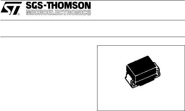
SOD 6
(Plastic)
DESCRIPTION
Transil diodes provide high overvoltage protection by clamping action. Their instantaneous reponse to transients makes them praticularly suited to protect voltage sensitive devices such as MOS Technology and low voltage supplied IC's.
ABSOLUTE RATINGS (limiting values)
.MECHANICAL CHARACTERISTICS
Body marked with : Logo, Date Code, Type Code and Cathode Band (for unidirectional
. types only).
Full compatibility with both gluing and paste
. soldering technologies.
. Excellent on board stability.
. Tinned copper leads.
High temperature resistant resin.
Symbol |
Parameter |
|
Value |
Unit |
|
|
|
|
|
Pp |
Peak pulse power dissipation |
Tamb = 25°C |
400 |
W |
|
See note 1 and derating curve Fig 1. |
|
|
|
|
|
|
|
|
P |
Power dissipation on infinite heatsink |
Tlead = 50°C |
5 |
W |
|
See note 1 and derating curve Fig 1. |
|
|
|
|
|
|
|
|
IFSM |
Non repetitive surge peak forward current. |
Tamb = 25°C |
50 |
A |
|
For unidirectional types. |
t =10 ms |
|
|
|
|
|
|
|
Tstg |
Storage and junction temperature range |
|
- 65 to + 175 |
°C |
Tj |
|
|
150 |
°C |
TL |
Maximum lead temperature for soldering |
|
260 |
°C |
|
during 10 s. |
|
|
|
|
|
|
|
|
November 1992 |
1/7 |

SM4Txx
THERMAL RESISTANCES
Symbol |
Parameter |
Value |
Unit |
|
|
|
|
Rth (j-l) |
Junction-leads on infinite heatsink |
20 |
°C/W |
Rth (j-a) |
Junction to ambiant. on printed circuit. |
100 |
°C/W |
|
With standard footprint dimensions. |
|
|
|
|
|
|
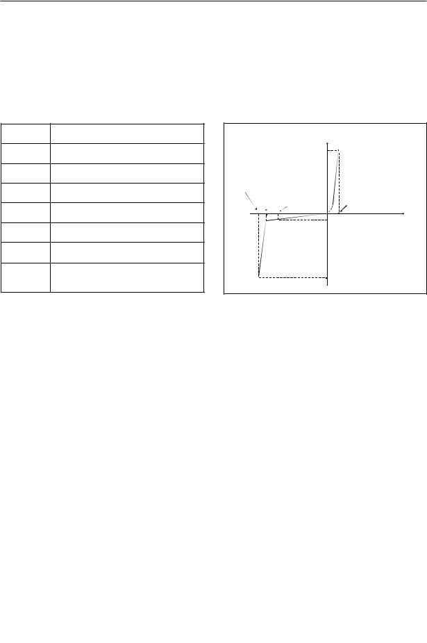
ELECTRICAL CHARACTERISTICS |
|
|
|
Symbol |
Parameter |
|
I |
|
|
|
|
VRM |
Stand-off voltage. |
|
IF |
|
|
||
VBR |
Breakdown voltage. |
|
|
VCL |
VCL |
VBR |
|
Clamping voltage. |
VRM |
V F |
|
|
|
||
IRM |
Leakage current @ VRM. |
|
V |
|
|
|
I RM |
IPP |
Surge current. |
|
|
αT |
Voltage temperature coefficient. |
|
|
VF |
Forward Voltage drop |
|
I PP |
|
VF < 3.5V @ IF = 25 A. |
|
|
|
TYPES |
|
IRM @ VRM |
VBR |
@ IR |
VCL @ IPP |
VCL @ IPP |
αT |
C |
||||||||
|
|
max |
|
min |
nom max |
|
|
max |
|
max |
|
max |
typ |
||||
|
|
|
|
|
|
|
|
|
|||||||||
|
|
|
|
|
|
|
|
note2 |
|
|
10/1000μs |
8/20μs |
note3 |
note4 |
|||
Uni |
|
Bi |
|
μA |
V |
V |
V |
V |
mA |
V |
A |
V |
A |
10-4/°C |
( F) |
||
directional |
* |
directional |
* |
|
|
|
|
|
|
|
|
|
|
|
|
|
P |
|
|
|
|
|
|
|
|
|
|
|
|
|
|
||||
SM4T6V8 |
QD |
SM4T6V8C |
VD |
1000 |
5.8 |
6.45 |
6.8 |
7.48 |
10 |
10.5 |
38 |
13.4 |
174 |
5.7 |
3500 |
||
SM4T6V8A |
QE |
SM4T6V8CA |
VE |
1000 |
5.8 |
6.45 |
6.8 |
7.14 |
10 |
10.5 |
38 |
13.4 |
174 |
5.7 |
3500 |
||
SM4T7V5 |
QF |
SM4T7V5C |
VF |
500 |
6.4 |
7.13 |
7.5 |
8.25 |
10 |
11.3 |
35.4 |
14.5 |
160 |
6.1 |
3100 |
||
SM4T7V5A |
QG |
SM4T7V5CA |
VG |
500 |
6.4 |
7.13 |
7.5 |
7.88 |
10 |
11.3 |
35.4 |
14.5 |
160 |
6.1 |
3100 |
||
SM4T10 |
QN |
SM4T10C |
VN |
10 |
8.55 |
9.5 |
10 |
11 |
1 |
|
14.5 |
27.6 |
18.6 |
124 |
7.3 |
2000 |
|
SM4T10A |
QP |
SM4T10CA |
VP |
10 |
8.55 |
9.5 |
10 |
10.5 |
1 |
|
14.5 |
27.6 |
18.6 |
124 |
7.3 |
2000 |
|
SM4T12 |
QS |
SM4T12C |
VS |
5 |
10.2 |
11.4 |
12 |
13.2 |
1 |
|
16.7 |
24 |
21.7 |
106 |
7.8 |
1550 |
|
SM4T12A |
QT |
SM4T12CA |
VT |
5 |
10.2 |
11.4 |
12 |
12.6 |
1 |
|
16.7 |
24 |
21.7 |
106 |
7.8 |
1550 |
|
SM4T15 |
QW |
SM4T15C |
VW |
5 |
12.8 |
14.3 |
15 |
16.5 |
1 |
|
21.2 |
19 |
27.2 |
85 |
8.4 |
1200 |
|
SM4T15A |
QX |
SM4T15CA |
VX |
5 |
12.8 |
14.3 |
15 |
15.8 |
1 |
|
21.2 |
19 |
27.2 |
85 |
8.4 |
1200 |
|
SM4T18 |
RD |
SM4T18C |
UD |
5 |
15.3 |
17.1 |
18 |
19.8 |
1 |
|
25.2 |
16 |
32.5 |
71 |
8.8 |
975 |
|
SM4T18A |
RE |
SM4T18CA |
UE |
5 |
15.3 |
17.1 |
18 |
18.9 |
1 |
|
25.2 |
16 |
32.5 |
71 |
8.8 |
975 |
|
SM4T22 |
RH |
SM4T22C |
UH |
5 |
18.8 |
20.9 |
22 |
24.2 |
1 |
|
30.6 |
13 |
39.3 |
59 |
9.2 |
800 |
|
SM4T22A |
RK |
SM4T22CA |
UK |
5 |
18.8 |
20.9 |
22 |
23.1 |
1 |
|
30.6 |
13 |
39.3 |
59 |
9.2 |
800 |
|
SM4T24 |
RL |
SM4T24C |
UL |
5 |
20.5 |
22.8 |
24 |
26.4 |
1 |
|
33.2 |
12 |
42.8 |
54 |
9.4 |
725 |
|
SM4T24A |
RM |
SM4T24CA |
UM |
5 |
20.5 |
22.8 |
24 |
25.2 |
1 |
|
33.2 |
12 |
42.8 |
54 |
9.4 |
725 |
|
SM4T27 |
RN |
SM4T27C |
UN |
5 |
23.1 |
25.7 |
27 |
29.7 |
1 |
|
37.5 |
10.7 |
48.3 |
48 |
9.6 |
625 |
|
SM4T27A |
RP |
SM4T27CA |
UP |
5 |
23.1 |
25.7 |
27 |
28.4 |
1 |
|
37.5 |
10.7 |
48.3 |
48 |
9.6 |
625 |
|
SM4T30 |
RQ |
SM4T30C |
UQ |
5 |
25.6 |
28.5 |
30 |
33 |
1 |
|
41.5 |
9.6 |
53.5 |
43 |
9.7 |
575 |
|
SM4T30A |
RR |
SM4T30C4 |
UR |
5 |
25.6 |
28.5 |
30 |
31.5 |
1 |
|
41.5 |
9.6 |
53.5 |
43 |
9.7 |
575 |
|
SM4T33 |
RS |
SM4T33C |
US |
5 |
28.2 |
31.4 |
33 |
36.3 |
1 |
|
45.7 |
8.8 |
59.0 |
39 |
9.8 |
510 |
|
SM4T33A |
RT |
SM4T33CA |
UT |
5 |
28.2 |
31.4 |
33 |
34.7 |
1 |
|
45.7 |
8.8 |
59.0 |
39 |
9.8 |
510 |
|
SM4T36 |
RU |
SM4T36C |
UU |
5 |
30.8 |
34.2 |
36 |
39.6 |
1 |
|
49.9 |
8 |
64.3 |
36 |
9.9 |
480 |
|
SM4T36A |
RV |
SM4T36CA |
UV |
5 |
30.8 |
34.2 |
36 |
37.8 |
1 |
|
49.9 |
8 |
64.3 |
36 |
9.9 |
480 |
|
SM4T39 |
RW |
SM4T39C |
UW |
5 |
33.3 |
37.1 |
39 |
42.9 |
1 |
|
53.9 |
7.4 |
69.7 |
33 |
10.0 |
450 |
|
SM4T39 |
RX |
SM4T39 |
UX |
5 |
33.3 |
37.1 |
39 |
41.0 |
1 |
|
53.9 |
7.4 |
69.7 |
33 |
10.0 |
450 |
|
|
|
|
|
|
|
|
|
|
|
|
|
|
|
|
|
|
|
2/7 |
|
|
|
|
|
|
|
|
|
|
|
|
|
|
|
|
|
|
|
|
|
|
|
|
|
|
|
|
|
|
|
|
|
|
|
142

SM4Txx
|
TYPES |
|
IRM @ VRM |
VBR |
@ |
IR |
VCL @ IPP |
VCL @ IPP |
αT |
C |
||||||
|
|
|
|
max |
|
min |
nom max |
|
max |
|
max |
|
max |
typ |
||
|
|
|
|
|
|
|
note2 |
|
10/1000μs |
8/20μs |
note3 |
note4 |
||||
Uni |
|
Bi |
|
μA |
V |
V |
V |
|
V |
mA |
V |
A |
V |
A |
10-4/°C |
( F) |
directional |
* |
directional |
* |
|
|
|
|
|
|
|
|
|
|
|
|
P |
|
|
|
|
|
|
|
|
|
|
|
|
|
||||
SM4T68 |
SN |
SM4T68C |
WN |
5 |
58.1 |
64.6 |
68 |
|
74.8 |
1 |
92 |
4.3 |
121 |
19 |
10.4 |
270 |
SM4T68A |
SP |
SM4T68CA |
WP |
5 |
58.1 |
64.6 |
68 |
|
71.4 |
1 |
92 |
4.3 |
121 |
19 |
10.4 |
270 |
SM4T100 |
SW |
SM4T100C |
WW |
5 |
85.5 |
95.0 |
100 |
|
110 |
1 |
137 |
2.9 |
178 |
13 |
10.6 |
200 |
SM4T100A |
SX |
SM4T100CA |
WX |
5 |
85.5 |
95.0 |
100 |
|
105 |
1 |
137 |
2.9 |
178 |
13 |
10.6 |
200 |
SM4T150 |
TH |
SM4T150C |
XH |
5 |
128 |
143 |
150 |
|
165 |
1 |
207 |
2.0 |
265 |
9 |
10.8 |
145 |
SM4T150A |
TK |
SM4T150CA |
XK |
5 |
128 |
143 |
150 |
|
158 |
1 |
207 |
2.0 |
265 |
9 |
10.8 |
145 |
SM4T200 |
TS |
SM4T200C |
XS |
5 |
171 |
190 |
200 |
|
220 |
1 |
274 |
1.5 |
353 |
6.5 |
10.8 |
120 |
SM4T200A |
TT |
SM4T200CA |
XT |
5 |
171 |
190 |
200 |
|
210 |
1 |
274 |
1.5 |
353 |
6.5 |
10.8 |
120 |
SM4T220 |
TU |
SM4T220C |
XU |
5 |
188 |
209 |
220 |
|
242 |
1 |
328 |
1.4 |
388 |
6 |
10.8 |
110 |
SM4T220A |
TV |
SM4T220CA |
XV |
5 |
188 |
209 |
220 |
|
231 |
1 |
328 |
1.4 |
388 |
6 |
10.8 |
110 |
|
|
|
|
|
|
|
|
|
|
|
|
|
|
|
|
|
All parameters tested at 25 °C, except where indicated.
* = Marking
|
|
|
|
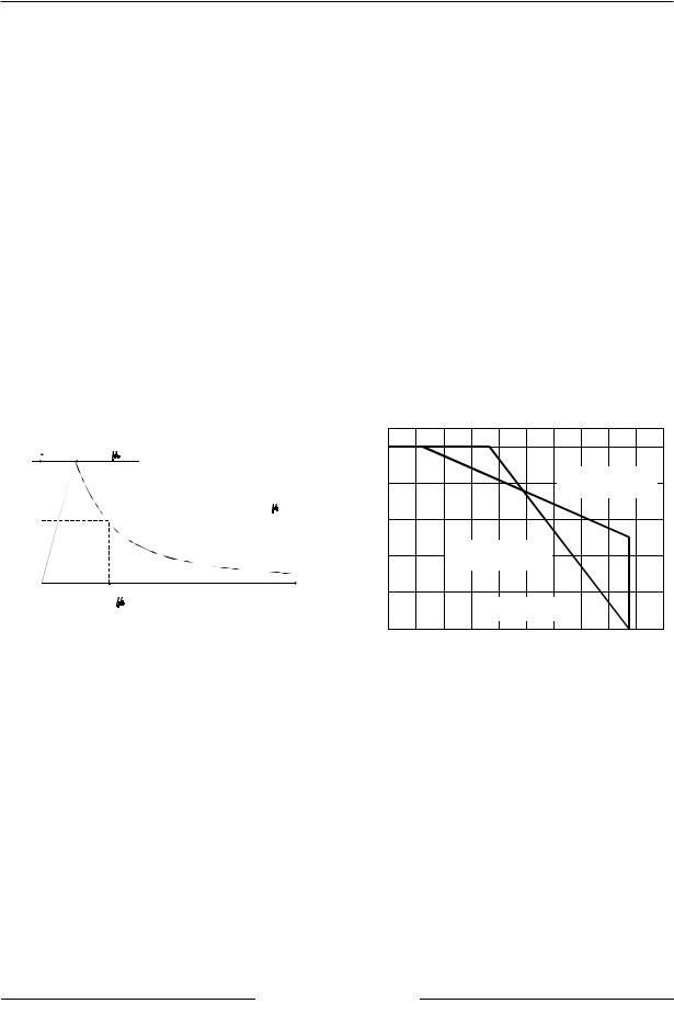
Figure 1: Power dissipation derating versus |
|
|||||
|
|
|
|
ambient temperature |
|
|
|
|||
% I PP |
|
|
|
100 % |
|
|
|
|
|
|
|
10 |
s |
|
|
|
|
|
|
|
|
100 |
|
|
|
|
|
|
|
|
||
|
|
|
|
|
|
|
|
|
|
|
|
|
|
|
80 % |
|
|
|
|
Peak Power |
|
|
|
|
|
|
|
|
(on printed circuit). |
|||
|
|
|
|
|
|
|
|
|||
|
|
PULSE WAVEFORM 10/1000 |
s |
|
|
|
|
|
|
|
50 |
|
|
|
60 % |
|
|
|
|
|
|
|
|
|
|
40 % |
|
|
Average Power |
|
|
|
|
|
|
|
|
(on infinite heatsink). |
|
|
|||
|
|
|
|
|
|
|
|
|||
0 |
|
|
t |
20 % |
|
|
|
|
|
|
|
1000 |
s |
|
|
|
|
|
|
|
|
|
|
|
|
|
|
Tamb (˚c) |
|
|
||
|
|
|
|
|
|
|
|
|
|
|
|
|
|
|
0% |
|
|
|
|
|
|
Note 1 : |
For surges greater than the maximum values, |
|
0 |
20 |
40 |
60 |
80 100 120 |
140 160 180 |
200 |
|
|
the diode will present a short-circuit Anode - Cathode. |
|
|
|
|
|
|
|
||
Note 2 : Pulse test: TP < 50 ms.
Note 3 : VBR = αT * (Ta - 25) * VBR(25°C).
Note 4 : VR = 0 V, F = 1 MHz. For bidirectional types, capacitance value is divided by 2.
3/7
143
 Loading...