


 Loading...
OPERATION MANUAL
Packaged water-cooled water chillers
EWWP045KAW1M
EWWP055KAW1M
EWWP065KAW1M
ECB2MUAW
ECB3MUAW
EWWP045KAW1M EWWP055KAW1M ECB2MUAW EWWP065KAW1M ECB3MUAW
Packaged water-cooled water chillers |
Operation manual |
CONTENTS |
Page |
Introduction ....................................................................................... |
1 |
Technical specifications ............................................................................. |
2 |
Electrical specifications ............................................................................. |
2 |
Description ........................................................................................ |
3 |
Function of the main components.............................................................. |
4 |
Safety devices............................................................................................ |
5 |
Internal wiring - Parts table........................................................................ |
5 |
Before operation................................................................................ |
6 |
Checks before initial start-up ..................................................................... |
6 |
Water supply.............................................................................................. |
6 |
General recommendations ........................................................................ |
6 |
Operation 32~72 Hp.......................................................................... |
6 |
Digital controller......................................................................................... |
6 |
Working with the 32~72 Hp units............................................................... |
6 |
Advanced features of the digital controller................................................. |
9 |
Troubleshooting............................................................................... |
14 |
Maintenance.................................................................................... |
15 |
Important information regarding the refrigerant used .............................. |
15 |
Maintenance activities ............................................................................. |
15 |
Disposal requirements............................................................................. |
15 |
READ THIS MANUAL ATTENTIVELY BEFORE STARTING UP THE UNIT. DO NOT THROW THIS MANUAL AWAY. KEEP IT IN YOUR FILES FOR FUTURE REFERENCE. Read the chapter "User settings menu" on page 9 before changing the parameters.
The English text is the original instruction. Other languages are translations of the original instructions.
This appliance is not intended for use by persons, including children, with reduced physical, sensory or mental capabilities, or lack of experience and knowledge, unless they have been given supervision or instruction concerning use of the appliance by a person responsible for their safety.
Children should be supervised to ensure that they do not play with the appliance.
INTRODUCTION
This operation manual concerns packaged water-cooled water chillers of the Daikin EWWP-KA series. These units are provided for indoor installation and used for cooling and/or heating applications. The units can be combined with Daikin fan coil units or air handling units for air conditioning purposes. They can also be used for supplying water for process cooling.
This manual has been prepared to ensure adequate operation and maintenance of the unit. It will tell you how to use the unit properly and will provide help if problems occur. The unit is equipped with safety devices, but they will not necessarily prevent all problems caused by improper operation or inadequate maintenance.
In case of persisting problems contact your local dealer.
Before starting up the unit for the first time, make sure that it has been properly installed. It is therefore necessary to carefully read the installation manual supplied with the unit and the recommendations listed in "Checks before initial start-up" on page 6.
Operation manual |
EWWP045~065KAW1M + ECB2+3MUAW |
1 |
Packaged water-cooled water chillers |
4PW61664-1A - 2012.04 |

Technical specifications(1)
General |
Hp |
32 |
36 |
40 |
|
44 |
48 |
52 |
56 |
60 |
64 |
68 |
72 |
Nominal cooling |
(kW) |
86 |
99 |
112 |
|
121 |
130 |
142 |
155 |
168 |
177 |
186 |
195 |
capacity(a) |
|
||||||||||||
|
|
|
|
|
|
|
|
|
|
|
|
|
|
Nominal input(b) |
(kW) |
24.2 |
28.1 |
32.0 |
|
34.3 |
36.6 |
40.2 |
44.1 |
48.0 |
50.3 |
52.6 |
54.9 |
Dimensions HxWxD |
(mm) |
|
1200x600x1200 |
|
|
|
1800x600x1200 |
|
|
||||
|
|
|
|
|
|
|
|
|
|
|
|
|
|
Machine weight |
(kg) |
600 |
620 |
640 |
|
654 |
668 |
920 |
940 |
960 |
974 |
988 |
1002 |
Connections |
|
|
|
|
|
|
|
|
|
|
|
|
|
• water inlet |
(inch) |
|
|
2x 2x G 1-1/2 |
|
|
|
|
3x 2x G 1-1/2 |
|
|
||
|
|
|
|
2x 2x G 1-1/2 |
|
|
|
|
3x 2x G 1-1/2 |
|
|
||
• water outlet |
(inch) |
|
|
|
|
|
|
|
|
||||
Compressor |
|
|
|
|
|
|
|
|
|
|
|
|
|
Type |
|
|
|
|
|
|
hermetically sealed scroll |
|
|
|
|
||
|
|
|
2x |
|
|
2x |
|
4x |
2x |
|
4x |
2x |
|
|
|
4x |
4x |
4x |
JT212DA-YE |
JT212DA-YE |
6x |
JT300DA-YE |
JT300DA-YE |
6x |
|||
Qty x model |
|
JT212DA-YE + |
JT300DA-YE + |
||||||||||
|
JT212DA-YE |
JT300DA-YE |
JT335DA-YE |
+ 2x |
+ 4x |
JT300DA-YE |
+ 2x |
+ 4x |
JT335DA-YE |
||||
|
|
2x JT300DA-YE |
2x JT335DA-YE |
||||||||||
|
|
|
|
|
|
|
|
JT300DA-YE |
JT300DA-YE |
|
JT335DA-YE |
JT335DA-YE |
|
Speed |
(rpm) |
|
|
2900 |
|
|
|
|
|
2900 |
|
|
|
Oil type |
|
|
|
FVC 68D |
|
|
|
|
FVC 68D |
|
|
||
Oil charge volume |
(l) |
|
|
4x 2.7 |
|
|
|
|
6x 2.7 |
|
|
||
Evaporator |
|
|
|
|
|
|
|
|
|
|
|
|
|
Type |
|
|
|
|
|
|
brased plate heat exchanger |
|
|
|
|
||
Qty |
|
|
|
2 |
|
|
|
|
|
|
3 |
|
|
Nominal water flow |
(l/min) |
247 |
284 |
321 |
|
347 |
373 |
407 |
444 |
482 |
507 |
533 |
559 |
Water flow range |
(l/min) |
202 - 493 |
232 - 568 |
262 - 642 |
|
283 - 694 |
304 - 745 |
333 - 814 |
363 - 889 |
393 -963 |
414 - 1015 |
435 - 1066 |
456 - 1118 |
Condenser |
|
|
|
|
|
|
|
|
|
|
|
|
|
Type |
|
|
|
|
|
|
brased plate heat exchanger |
|
|
|
|
||
Qty |
|
|
|
2 |
|
|
|
|
|
|
3 |
|
|
Nominal water flow |
(l/min) |
314 |
362 |
410 |
|
442 |
474 |
519 |
567 |
614 |
647 |
679 |
711 |
|
|
157 - 629 |
181 -724 |
205 - 819 |
|
221 - 883 |
237 - 948 |
260-1038 |
283-1133 |
307-1229 |
323-1293 |
339-1357 |
355-1422 |
Water flow range |
(l/min) |
|
|||||||||||
|
|
|
|
|
|
|
|
|
|
|
|
|
|
(a)The nominal cooling capacity is based on:
-entering water temperature of 12°C
-chilled water temperature of 7°C
-condenser in/out water temperature of 30/35°C
(b)The nominal input includes total input of the unit: compressor, control circuit and water pumps.
Electrical specifications(1)
General |
Hp |
32 |
36 |
40 |
44 |
48 |
52 |
56 |
60 |
64 |
68 |
72 |
|
Power supply |
|
|
|
|
|
|
|
|
|
|
|
|
|
• Phase |
|
|
|
3N~ |
|
|
|
|
|
3N~ |
|
|
|
• Frequency |
(Hz) |
|
|
50 |
|
|
|
|
|
50 |
|
|
|
• Voltage |
(V) |
|
|
400 |
|
|
|
|
|
400 |
|
|
|
• Voltage tolerance |
(%) |
|
|
±10 |
|
|
|
|
|
±10 |
|
|
|
Unit |
|
|
|
|
|
|
|
|
|
|
|
|
|
• Nominal running |
(A) |
41.6 |
47.0 |
52.4 |
56.2 |
60.0 |
67.8 |
73.2 |
78.6 |
82.4 |
86.2 |
90.0 |
|
current |
|||||||||||||
|
|
|
|
|
|
|
|
|
|
|
|
||
• Maximum running |
(A) |
56 |
64 |
72 |
76 |
80 |
92 |
100 |
108 |
112 |
116 |
120 |
|
current |
|||||||||||||
|
|
|
|
|
|
|
|
|
|
|
|
||
• Recommended fuses |
(A) |
3x 63 |
3x 63 |
3x 80 |
3x 80 |
3x 80 |
3x 100 |
3x 100 |
3x 125 |
3x 125 |
3x 125 |
3x 125 |
|
according to IEC 269-2 |
|||||||||||||
|
|
|
|
|
|
|
|
|
|
|
|
||
Compressor |
|
|
|
|
|
|
|
|
|
|
|
|
|
• Phase |
|
|
|
3~ |
|
|
|
|
|
3~ |
|
|
|
• Frequency |
(Hz) |
|
|
50 |
|
|
|
|
|
50 |
|
|
|
• Voltage |
(V) |
|
|
400 |
|
|
|
|
|
400 |
|
|
|
• Nominal running |
(A) |
10.4 |
10.4/13.1 |
13.1 |
13.1/15 |
15 |
10.4/13.1 |
10.4/13.1 |
13.1 |
13.1/15 |
13.1/15 |
15 |
|
current |
|||||||||||||
|
|
|
|
|
|
|
|
|
|
|
|
||
|
|
|
|
|
|
|
|
|
|
|
|
|
(1) Refer to the engineering data book for the complete list of specifications.
EWWP045~065KAW1M + ECB2+3MUAW |
Operation manual |
Packaged water-cooled water chillers |
2 |
4PW61664-1A - 2012.04 |
DESCRIPTION
|
|
|
|
|
|
|
|
|
|
|
|
|
17 |
5 |
|
|
|
|
|
|
|
|
|
|
|
|
|
|
|
|
|
|
|
|
|
|
|
|
|
|
|
|||
|
|
|
|
|
|
|
|
|
|
|
|
|||
|
|
|
|
|
|
|
|
|
|
|
|
26 |
11 |
|
|
|
|
|
|
|
|
|
|
|
|
|
|||
|
|
|
|
|
|
|
|
|
|
|
|
23 |
14 |
|
|
|
|
|
|
|
|
|
|
|
|
|
|||
|
|
|
|
|
|
|
|
|
|
|
|
|
|
20 |
|
|
<![if ! IE]> <![endif]>Hp |
|
|
|
|
|
|
|
|
8 |
|||
|
|
|
|
|
|
|
|
27 |
||||||
|
||||||||||||||
|
|
<![if ! IE]> <![endif]>32~48 |
|
|
|
|
|
|
|
|
|
|
18 |
6 |
| <![if ! IE]> <![endif]>Hp |
|
|
|
|
|
|
|
|
|
|
12 |
|||
| <![if ! IE]> <![endif]>52~72 |
|
|
|
|
|
|
|
|
|
|
|
|
24 |
15 |
|
|
|
|
|
|
|
|
|
|
|
|
|||
|
|
|
|
|
|
|
|
|
|
|
|
|
|
21 |
|
|
|
|
|
|
|
|
|
|
|
|
9 |
||
|
|
|
|
|
|
|
|
|
|
|
|
27 |
||
|
|
|
|
|
|
|
|
|
|
|
||||
|
|
|
|
|
|
|
|
|
|
|
|
19 |
7 |
|
|
|
|
|
|
|
|
|
|
|
|
|
|
||
|
|
|
|
|
|
|
|
|
|
|
|
|||
|
|
|
|
|
|
|
|
|
|
|
|
|
|
13 |
|
|
|
|
|
|
|
|
|
|
|
25 |
16 |
||
|
|
|
|
|
|
|
|
|
|
|
||||
|
|
|
|
|
|
|
|
|
|
|
|
|
|
22 |
|
|
|
|
|
|
|
|
|
|
|
|
27 |
10 |
|
|
|
|
|
|
|
|
|
|
|
|
|
|||
|
|
|
|
|
|
|
|
|
|
|
||||
|
|
|
|
|
|
|
|
|
|
|
|
|
|
|
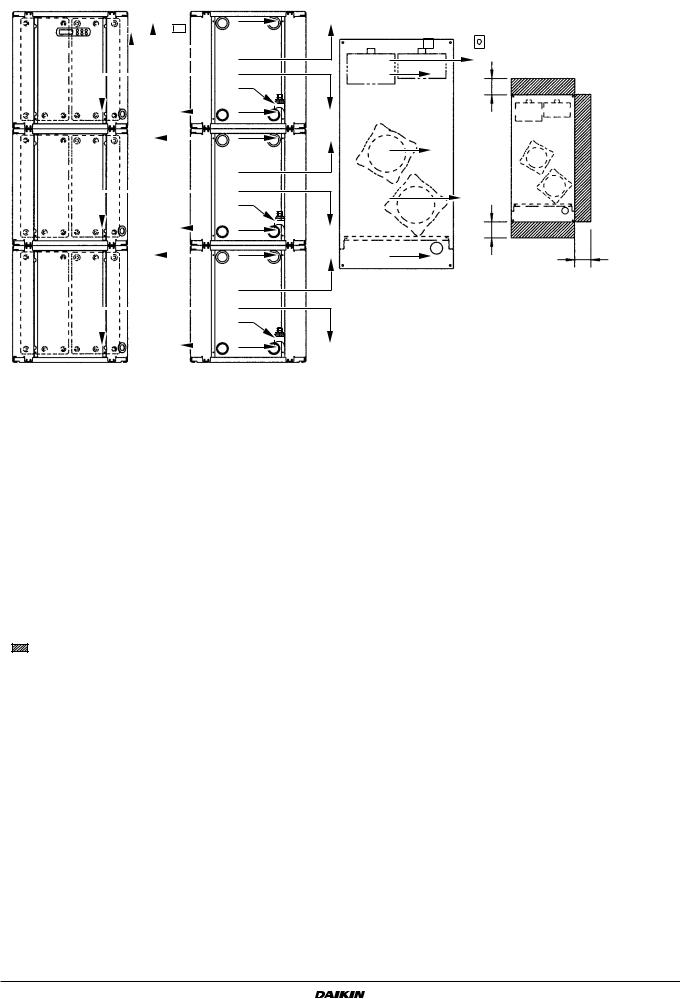
Figure - Main components
1Compressor
2Evaporator
3Condenser
4Switchbox
5Chilled water in 1
6Chilled water in 2
7Chilled water in 3
8Chilled water out 1
9Chilled water out 2
10 Chilled water out 3
11 Condenser water out 1
12 Condenser water out 2
13 Condenser water out 3
14 Condenser water in 1
Required space around the unit for service
2 |
|
3 |
<![if ! IE]> <![endif]>500 |
|
1
1
<![if ! IE]><![endif]>500
4
500
15Condenser water in 2
16Condenser water in 3
17Evaporator entering water temperature sensor 1
18Evaporator entering water temperature sensor 2
19Evaporator entering water temperature sensor 3
20Freeze up sensor 1
21Freeze up sensor 2
22Freeze up sensor 3
23Condenser entering water temperature sensor 1
24Condenser entering water temperature sensor 2
25Condenser entering water temperature sensor 3
26Digital display controller 32~72 Hp
27Power supply intake
Operation manual |
EWWP045~065KAW1M + ECB2+3MUAW |
3 |
Packaged water-cooled water chillers |
4PW61664-1A - 2012.04 |

Function of the main components
<![endif]>52~72 Hp
Water
inlet
Water
outlet
<![if ! IE]><![endif]>32~48 Hp
|
Filter |
|
|
|
S1HP |
|
|
|
Compressor |
|
|
|
M1C |
|
|
|
Q1D |
|
|
|
HP |
S4LP |
|
|
LP |
Evaporator |
|
R5T |
Condenser |
R4T |
|
|
Filter |
|
|
|
|
Water |
|
S2HP |
|
outlet |
|
Compressor |
R3T |
|
|
M2C |
Water |
||
|
|||
Q2D |
|
inlet |
|
|
|
||
HP |
S5LP |
|
|
LP |
|
|
S1HP |
|
M1C |
|
Q1D |
|
HP |
S4LP |
LP |
|
R5T |
R4T |
S2HP
R3T
M2C
Q2D |
|
HP |
S5LP |
LP
S1HP |
|
M1C |
|
Q1D |
|
HP |
S4LP |
LP |
|
R5T |
R4T |
S2HP
R3T
M2C
Q2D |
|
HP |
S5LP |
LP
Figure - Functional diagram
As the refrigerant circulates through the unit, changes in its state or condition occur. These changes are caused by the following main components:
■Compressor
The compressor (M*C) acts as a pump and circulates the refrigerant in the refrigeration circuit. It compresses the refrigerant vapour coming from the evaporator to a pressure at which it can easily be liquified in the condenser.
■Condenser
The function of the condenser is to change the state of the refrigerant from gaseous to liquid. The heat gained by the gas in the evaporator is discharged through the condenser and the vapour condenses to liquid.
■Filter
The filter installed behind the condenser removes small particles from the refrigerant to prevent blockage of the tubes.
■Expansion valve
The liquid refrigerant coming from the condenser enters the evaporator via an expansion valve. The expansion valve brings the liquid refrigerant to a pressure at which it can easily be evaporated in the evaporator.
■Evaporator
The main function of the evaporator is to take heat from the water that flows through it. This is done by turning the liquid refrigerant, coming from the condenser, into gaseous refrigerant.
■Water inlet/outlet connection
The water inlet and outlet connections allow an easy connection of the unit to the water circuit of the air handling unit or industrial equipment.
EWWP045~065KAW1M + ECB2+3MUAW |
Operation manual |
Packaged water-cooled water chillers |
4 |
4PW61664-1A - 2012.04 |

Safety devices
■Overcurrent relay
The overcurrent relay (K*S) is located in the switch box of the unit and protects the compressor motor in case of overload, phase failure or too low voltage. The relay is factory-set and may not be adjusted. When activated, the overcurrent relay has to be reset in the switch box and the controller needs to be reset manually.
■High-pressure switch
The high-pressure switch (S*HP) is installed on the discharge pipe of the unit and measures the condenser pressure (pressure at the outlet of the compressor). When the pressure is too high, the pressure switch is activated and the circuit stops.
When activated, it resets automatically, but the controller needs to be reset manually.
■Low pressure switch
The low-pressure switch (S*LP) is installed on the suction pipe of the unit and measures the evaporator pressure (pressure at the inlet of the compressor). When the pressure is too low, the pressure switch is activated and the circuit stops.
When activated, it resets automatically, but the controller needs to be reset manually.
■Reverse phase protector
The reverse phase protector (R1P) is installed in the switch box of the unit. It prevents the compressor from running in the wrong direction. If the unit does not start, two phases of the power supply must be inverted.
■Discharge thermal protector
The discharge thermal protector (Q*D) is activated when the temperature of the refrigerant leaving the compressor becomes too high. When the temperature returns to normal, the protector resets automatically, but the controller needs to be reset manually.
■Freeze-up protection
The freeze-up protection prevents the water in the evaporator from freezing during operation. When the outlet water temperature is too low, the controller disables the circuit. When the outlet water temperature returns to normal, the circuit can start up again.
When freeze-up protection occurs several times in a certain period, the freeze-up alarm will be activated and the circuit will be shut down. The cause of freezing up should be investigated and after outlet water temperature has risen enough, the alarm indicator on the controller needs to be reset manually.
■Additional interlock contact
To avoid that the unit could be started or run without water circulating through the water heat exchanger, an interlock contact (S11L) of e.g. a flow switch must be installed in the startup circuit of the unit.
Internal wiring - Parts table
Refer to the internal wiring diagram supplied with the unit. The abbreviations used are listed below:
A1P ........................ |
|
PCB terminal unit |
A2P ................ |
** .... |
PCB address card |
F1,2,3U .......... |
#..... |
Main fuses for the unit |
F5B,F6B ................. |
|
Automatic fuse for the control circuit/secondary |
|
|
of TR1 |
F8U ........................ |
|
Surge-proof fuse |
F9U ................ |
##... |
Surge-proof fuse |
H1P ................ |
*...... |
Indication lamp alarm |
H3P ................ |
*...... |
Indication lamp operation compressor (M1C) |
H4P ........................ |
|
Indication lamp operation compressor (M2C) |
K1A ........................ |
|
auxiliary contactor for high pressure |
K1M........................ |
|
Compressor contactor (M1C) |
K1P ................ |
*...... |
Pumpcontactor |
K2M........................ |
|
Compressor contactor (M2C) |
K4S......................... |
|
Overcurrent relay (M1C) |
|
||
K5S......................... |
|
Overcurrent relay (M2C) |
|
||
K19T....................... |
|
Timer, time delay for M2C |
|
||
M1C,M2C ............... |
|
Compressor motor |
|
||
PE |
........................... |
|
Main earth terminal |
|
|
Q1D........................ |
|
Discharge thermal protector (M1C) |
|||
Q2D........................ |
|
Discharge thermal protector (M2C) |
|||
R1P ........................ |
|
Reverse phase protector |
|
||
R3T......................... |
|
Evaporator inlet water temperature sensor |
|||
R4T......................... |
|
Evaporator outlet water temperature sensor |
|||
|
|
|
(Freeze up sensor) |
|
|
R5T......................... |
|
Condenser inlet temperature sensor |
|||
S1HP,S2HP ............ |
|
High pressure switch |
|
||
S4LP,S5LP ............. |
|
Low pressure switch |
|
||
S7S......................... |
|
Changeable digital input 1 |
|
||
S9S................. ...... |
* |
Changeable digital input 2 |
|
||
S10L............... ..... |
# |
Flowswitch |
|
||
S11L............... ..... |
# |
Contact that closes if the pump is working |
|||
S12S............... ..... |
# |
Main isolator switch |
|
||
TR1......................... |
|
Transfo 230 V 24 V for power supply of |
|||
|
|
|
controllers |
|
|
Y1R ........................ |
|
Reversing valve |
|
||
Y1S......................... |
|
Solenoid valve for injection line |
|||
X1 ........................... |
|
|
Connector for digital inputs, analog inputs, analog |
||
|
|
|
outputs and for power supply controller (A1P) |
||
X2........................... |
|
|
Connector for digital outputs (A1P) |
||
X3........................... |
|
|
Connector for (A1P) |
|
|
X4,X5,X6 ................ |
|
Interconnection connector Main ↔ Control |
|||
|
|
|
switchbox |
|
|
|
|
|
|
|
|
|
|
|
Not included with standard unit |
||
|
|
|
|
|
|
|
|
|
Not possible as option |
|
Possible as option |
|
|
|
|
|
|
|
Obligatory |
|
# |
|
## |
|
|
|
|
|
|
Not obligatory |
|
* |
|
** |
|
|
|
|
|
||
Terminal unit: Digital Inputs |
|
||||
X1 ......... |
(ID1 - GND) |
|
flowswitch |
|
|
X1 ......... |
(ID2 - GND) |
|
remote cooling/heating selection |
||
X1 ......... |
(ID3 - GND) |
|
high pressure switch + discharge protector + |
||
|
|
|
overcurrent |
|
|
X1 ......... |
(ID4 - GND) |
|
low pressure switch |
|
|
X1 ......... |
(ID5 - GND) |
|
remote On/Off |
|
|
Terminal unit: Digital outputs (relays) |
|
||||
X2 ....... |
(C1/2 - NO1) |
|
compressor M1C on |
|
|
X2 ....... |
(C1/2 - NO2) |
|
compressor M2C on |
|
|
X2 ....... |
(C3/4 - NO3) |
|
voltage free contact for pump |
||
X2 ....... |
(C3/4 - NO4) |
|
voltage free contact for reversing valve |
||
X2 .......... |
(C5 - NO5) |
|
alarm voltage free contact |
|
|
Terminal unit: Analog inputs |
|
||||
X1 .......... |
(B1 - GND) |
|
evaporator inlet water temperature |
||
X1 .......... |
(B2 - GND) |
|
evaporator outlet water temperature (Freeze up |
||
|
|
|
sensor) |
|
|
X1 .......... |
(B3 - GND) |
|
condenser inlet water temperature |
||
Operation manual |
EWWP045~065KAW1M + ECB2+3MUAW |
5 |
Packaged water-cooled water chillers |
4PW61664-1A - 2012.04 |
Loading...