


 Loading...
Daikin FDM24PEVLK, FDM30PEVLK, FDM36PEVLK, FDM42PEVLK, FDM48PEVLK Operation manuals
...OPERATING AND INSTALLATION INSTRUCTIONS MANUAL
DUCTED AIR-CONDITIONING UNIT (7.0-14.0kW)
Unit Model: |
|
Indoor unit |
Outdoor unit |
FDM24PEVLK |
R24PEVLK |
FDM30PEVLK |
R30PEVLK |
FDM36PEVLK |
R36PEVLK |
FDM42PEVLK |
R42PETLK/R42PEYLK |
FDM48PEVLK |
R48PETLK/R48PEYLK |
FDYM24PEVLK |
RY24PEVLK |
FDYM30PEVLK |
RY30PEVLK |
FDYM36PEVLK |
RY36PEVLK |
FDYM42PEVLK |
RY42PETLK/RY42PEYLK |
FDYM48PEVLK |
RY48PETLK/RY48PEYLK |
English
User Notice
Ensure unified power supply for each indoor unit.
Never install wired controller in wet place or under sunlight directly.
Shielding twisted pair line must be adopted as signal line or wiring (communication) of wired controller once the unit is installed in the place where there is electromagnetic interference.
Make sure communication line is connected into correct port to avoid communication malfunction.
Never knock, throw or frequently disassemble the wired controller.
Never operate the wired controller with wet hand.

|
|
Contents |
|
|
I |
SAFETY PRECAUTIONS....................................................................................................................... |
2 |
|
|
II |
DISPLAYING PART ................................................................................................................................ |
6 |
|
|
|
2.1 |
LCD Display of Wired Controller............................................................................................................................................ |
6 |
|
|
2.2 |
Instruction to LCD Display ..................................................................................................................................................... |
7 |
|
III |
BUTTONS............................................................................................................................................... |
8 |
|
|
|
3.1 |
Silk Screen of Buttons ........................................................................................................................................................... |
8 |
|
|
3.2 |
Instruction to Function of Buttons.......................................................................................................................................... |
8 |
|
IV INSTALLATION OF WIRED CONTROLLER AND PROJECT DEBUGGING........................................ |
9 |
|
||
|
4.1 |
Installation of Wired Controller .............................................................................................................................................. |
9 |
|
|
4.2 |
Project Debugging ............................................................................................................................................................... |
10 |
|
V |
..........................................................................................................INSTRUCTION TO OPERATION |
11 |
|
|
|
5.1 |
On/Off.................................................................................................................................................................................. |
11 |
|
|
5.2 |
Mode Setting ....................................................................................................................................................................... |
11 |
|
|
5.3 Temperature Setting ............................................................................................................................................................ |
12 |
|
|
|
5.4 |
Fan Speed Setting............................................................................................................................................................... |
12 |
|
|
5.5 |
Swing Control Function ....................................................................................................................................................... |
13 |
|
|
5.6 Timer Setting ....................................................................................................................................................................... |
13 |
|
|
|
5.7 |
Air Exchange Setting* ......................................................................................................................................................... |
15 |
|
|
5.8 |
Sleep Setting ....................................................................................................................................................................... |
16 |
|
|
5.9 Turbo Function Setting......................................................................................................................................................... |
17 |
|
|
|
5.10 Save Function Setting ....................................................................................................................................................... |
17 |
|
|
|
5.11 E-heater setting ................................................................................................................................................................. |
19 |
|
|
|
5.12 Blow Function Setting........................................................................................................................................................ |
20 |
|
|
|
5.13 Quiet Function Setting....................................................................................................................................................... |
21 |
|
|
|
5.14 Debugging Functions......................................................................................................................................................... |
21 |
|
|
|
5.15 Other Functions................................................................................................................................................................. |
22 |
|
|
VI ERROR DISPLAY ................................................................................................................................. |
23 |
|
||
VII SETTING OF INDOOR ROOM SENSOR AND CHECKING OF OUTDOOR AMBIENT |
|
|
||
|
TEMPERATURE ................................................................................................................................... |
24 |
|
|
|
7.1 |
Setting of Double Indoor Room Sensors ............................................................................................................................. |
24 |
|
|
7.2 |
Checking of Outdoor Ambient Temperature ........................................................................................................................ |
24 |
|
|
7.3 |
Fresh Air Control* ................................................................................................................................................................ |
25 |
|
|
7.4 The head of delivery of the condensate drainage pump* .................................................................................................... |
25 |
|
|
VIII PROFILE DIMENSIONS OF INDOOR UNIT AND OUTDOOR UNIT .................................................. |
26 |
|
||
|
8.1 |
Dimensions of Indoor Unit ................................................................................................................................................... |
26 |
|
|
8.2 |
Dimensions of Outdoor Unit ................................................................................................................................................ |
27 |
|
IX UNIT INSTALLATION INSTRUCTIONS ............................................................................................... |
28 |
|
||
|
9.1 |
Precautions on Installation of Outdoor Unit......................................................................................................................... |
28 |
|
|
9.2 |
Precautions on Installation of Indoor Unit............................................................................................................................ |
28 |
|
|
9.3 |
Level Check of the Indoor Unit ............................................................................................................................................ |
30 |
|
|
9.4 |
Installation of Rectangular Air Pipe ..................................................................................................................................... |
30 |
|
|
9.5 |
Installation of Condensate Pipe........................................................................................................................................... |
31 |
|
|
9.6 |
Design of Drainage Pipeline ................................................................................................................................................ |
31 |
|
|
9.7 Testing of Drainage System................................................................................................................................................. |
31 |
|
|
|
9.8 |
Selection of Connecting Pipe .............................................................................................................................................. |
32 |
|
|
9.9 |
Connection of Pipeline ........................................................................................................................................................ |
32 |
|
|
9.10 Installation of Protective Layer of Connecting Pipe ........................................................................................................... |
36 |
|
|
|
9.11 Position and Method of Installing Wire Controller.............................................................................................................. |
37 |
|
|
|
9.12 Electrical Installation.......................................................................................................................................................... |
38 |
|
|
|
9.13 Cable Connecting Diagram of Unit .................................................................................................................................... |
42 |
|
|
|
9.14 Troubleshooting and Maintenance..................................................................................................................................... |
45 |
|
|
X |
SPECIFICATIONS ................................................................................................................................ |
48 |
|
|
* means these units do not have these functions.
English |
1 |
I SAFETY PRECAUTIONS
To gain full advantage of the air conditioner’s functions and to avoid malfunction due to mishandling, we recommend that you read this instruction manual carefully before use.
This air conditioner is classified under “appliances not accessible to the general public”.
Please read these “SAFETY PRECAUTIONS” carefully before installing air conditioning equipment and be sure to install it correctly.
After completing installation, conduct a trial operation to check for faults and explain to the customer how to operate the air conditioner and take care of it with the aid of the operation manual. Ask the customer to store the installation manual along with the operation manual for future reference.
This air conditioner comes under the term “appliances not accessible to the general public”.
The precautions described herein are classified as WARNING and CAUTION. They both contain important information regarding safety. Be sure to observe all precautions without fail.
Meaning of WARNING and CAUTION notices.
 WARNING .......... Failure to follow these instructions properly may result in personal injury or loss of life.
 CAUTION........... Failure to observe these instructions properly may result in property damage or personal injury, which may be serious depending on the circumstances.
After reading, keep this manual in a convenient place so that you can refer to it whenever necessary. If the equipment is transferred to a new user, be sure also to hand over the manual.
WARNING
•Be aware that prolonged, direct exposure to cool or warm air from the air conditioner, or to air that is too cool or too warm can be harmful to your physical condition and health.
•When the air conditioner is malfunctioning (giving off a burning odour, etc.) turn off power to the unit and contact your local dealer.
Continued operation under such circumstances may result in a failure, electric shocks or fire hazards.
•Consult your local dealer about installation work.
Doing the work yourself may result in water leakage, electric shocks or fire hazards.
•Consult your local dealer regarding modification, repair and maintenance of the air conditioner. Improper workmanship may result in water leakage, electric shocks or fire hazards.
•Do not place objects, including rods, your fingers, etc., in the air inlet or outlet. Injury may result due to contact with the air conditioner’s highspeed fan blades.
•Beware of fire in case of refrigerant leakage.
If the air conditioner is not operating correctly, i.e. not generating cool or warm air, refrigerant leakage could be the cause.
Consult your dealer for assistance.
The refrigerant within the air conditioner is safe and normally does not leak.
However, in the event of a leakage, contact with a naked burner, heater or cooker may result in generation of noxious gas.
Do not longer use the air conditioner until a qualified service person confirms that the leakage has been repaired.
•Consult your local dealer regarding what to do in case of refrigerant leakage.
When the air conditioner is to be installed in a small room, it is necessary to take proper measures so that the amount of any leaked refrigerant does not exceed the concentration limit in the event of a leakage. Otherwise, this may lead to an accident due to oxygen depletion.
•Contact professional personnel about attachment of accessories and be sure to use only accessories specified by the manufacturer.
If a defect results from your own workmanship, it may result in water leaks, electric shock or fire.
•Consult your local dealer regarding relocation and reinstallation of the air conditioner. Improper installation work may result in leakage, electric shocks or fire hazards.
•Be sure to use fuses with the correct ampere reading.
Do not use improper fuses, copper or other wires as a substitute, as this may result in electric shock, fire, injury or damage to the unit.
2 |
English |

•Be sure to earth the unit.
Do not earth the unit to a utility pipe, lightning conductor or telephone earth lead. Imperfect earthing may result in electric shocks or fire.
A high surge current from lightning or other sources may cause damage to the air conditioner.
•Be sure to install an earth leakage breaker.
Failure to install an earth leakage breaker may result in electric shocks or fire.
•Consult the dealer if the air conditioner submerges owing to a natural disaster, such as a flood or typhoon. Do not operate the air conditioner in that case, or otherwise a malfunction, electric shock, or fire may result.
•Do not start or stop operating the air conditioner with the power supply breaker turned ON or OFF. Otherwise, fire or water leakage may result. Furthermore, the fan will rotate abruptly if power failure compensation is enabled, which may result in inlury.
•Do not use the product in the atmosphere contaminated with oil vapor, such as cooking oil or machine oil vapor. Oil vapor may cause crack damage, electric shocks, or fire.
•Do not use the product in places with excessive oily smoke, such as cooking rooms, or in places with flammable gas, corrosive gas, or metal dust.
Using the product in such places may cause fire or product failures.
•Do not use flammable materials (e.g., hairspray or insecticide) near the product. Do not clean the product with organic solvents such as paint thinner.
The use of organic solvents may cause crack damage to the product, electric shocks, or fire.
•Be sure to use a dedicated power supply for the air conditioner.
The use of any other power supply may cause heat generation, fire, or product failures.
•Ask your dealer or qualified personnel to carry out installation work.
Do not attempt to install the air conditioner yourself. Improper installation may result in water leakage, electric shocks or fire.
•Install the air conditioner in accordance with the instructions in this installation manual. Improper installation may result in water leakage, electric shocks or fire.
•Be sure to use only the specified accessories and parts for installation work.
Failure to use the specified parts may result in the unit falling, water leakage, electric shocks or fire.
•Install the air conditioner on a foundation strong enough to withstand the weight of the unit. A foundation of insufficient strength may result in the equipment falling and causing injury.
•Carry out the specified installation work after taking into account strong winds, typhoons or earthquakes. Failure to do so during installation work may result in the unit falling and causing accidents.
•Make sure that a separate power supply circuit is provided for this unit and that all electrical work is carried out by qualified personnel according to local laws and regulations and this installation manual.
An insufficient power supply capacity or improper electrical construction may lead to electric shocks or fire.
•Make sure that all wiring is secured, the specified wires are used, and that there is no strain on the terminal connections or wires.
Improper connections or securing of wires may result in abnormal heat build-up or fire.
•When wiring the power supply and connecting the wiring between the indoor and outdoor units, position the wires so that the control box lid can be securely fastened.
Improper positioning of the control box lid may result in electric shocks, fire or overheating terminals.
•If refrigerant gas leaks during installation, ventilate the area immediately. Toxic gas may be produced if the refrigerant comes into contact with fire.
•After completing installation, check for refrigerant gas leakage.
Toxic gas may be produced if the refrigerant gas leaks into the room and comes into contact with a source of fire, such as a fan heater, stove or cooker.
•Be sure to switch off the unit before touching any electrical parts.
•Be sure to earth the air conditioner.
Do not earth the unit to a utility pipe, lightning conductor or telephone earth lead. Imperfect earthing may result in electric shocks or fire.
A high surge current from lightning or other sources may cause damage to the air conditioner.
•Be sure to install an earth leakage breaker.
Failure to install an earth leakage breaker may result in electric shocks or fire.
English |
3 |

CAUTION
•Do not use the air conditioner for purposes other than those for which it is intended.
Do not use the air conditioner for cooling precision instruments, food, plants, animals or works of art as this may adversely affect the performance, quality and/or longevity of the object concerned.
•Do not remove the outdoor unit’s fan guard.
The guard protects against the unit’s high speed fan, which may cause injury.
•Do not place objects that are susceptible to moisture directly beneath the indoor or outdoor units.
Under certain conditions, condensation on the main unit or refrigerant pipes, air filter dirt or drain blockage may cause dripping, resulting in fouling or failure of the object concerned.
•To avoid oxygen depletion, ensure that the room is adequately ventilated if equipment such as a burner is used together with the air conditioner.
•After prolonged use, check the unit stand and its mounts for damage. If left in a damaged condition, the unit may fall and cause injury.
•Do not place flammable sprays or operate spray containers near the unit as this may result in fire.
•Before cleaning, be sure to stop unit operation, turn the breaker off or remove the power cord. Otherwise, an electric shock and injury may result.
•To avoid electric shocks, do not operate with wet hands.
•Do not place appliances that produce naked flames in places exposed to the air flow from the unit as this may impair combustion of the burner.
•Do not place heaters directly below the unit, as resulting heat can cause deformation.
•Do not allow a child to mount on the outdoor unit or avoid placing any object on it. Falling or tumbling may result in injury.
•Do not block air inlets nor outlets.
Impaired air flow may result in insufficient performance or trouble.
•Be sure that children, plants or animals are not exposed directly to airflow from the unit, as adverse effects may ensue.
•Do not wash the air conditioner with water, as this may result in electric shocks or fire.
•Do not install the air conditioner at any place where there is a danger of flammable gas leakage. In the event of a gas leakage, build-up of gas near the air conditioner may result in fire hazards.
•Do not put flammable containers, such as spray cans, within 1 m from the blow-off mouth.
The containers may explode because the warm air output of the indoor or outdoor unit will affect them.
•Arrange the drain to ensure complete drainage.
If proper drainage from the outdoor drain pipe does not occur during air conditioner operation, there could be a blockage due to dirt and debris build-up in the pipe.
This may result in a water leakage from the indoor unit.
Under these circumstances, stop air conditioner operation and consult your dealer for assistance.
•The appliance is not intended for use by unattended young children or infirm persons. Impairment of bodily functions and harm to health may result.
•Children should be supervised to ensure that they do not play with the unit or its remote controller. Accidental operation by a child may result in impairment of bodily functions and harm health.
•Do not let children play on or around the outdoor unit. If they touch the unit carelessly, injury may be caused.
•Consult your dealer regarding cleaning the inside of the air conditioner.
Improper cleaning may cause breakage of plastic parts, water leakage and other damage as well as electric shocks.
•To avoid injury, do not touch the air inlet or aluminium fins of the unit.
•Do not place objects in direct proximity of the outdoor unit and do not let leaves and other debris accumulate around the unit.
Leaves are a hotbed for small animals which can enter the unit. Once in the unit, such animals can cause malfunctions, smoke or fire when making contact with electrical parts.
•Never touch the internal parts of the controller.
Do not remove the front panel. Touching certain internal parts will cause electric shocks and damage to the unit. Please consult your dealer about checking and adjustment of internal parts.
•Do not leave the remote controller wherever there is a risk of wetting.
If water gets into the remote controller there is a risk of electrical leakage and damage to electronic components.
4 |
English |

•Watch your steps at the time of air filter cleaning or inspection. High-place work is required, to which utmost attention must be paid.
If the scaffold is unstable, you may fall or topple down, thus causing injury.
•While following the instructions in this installation manual, install drain piping to ensure proper drainage and insulate piping to prevent condensation.
Improper drain piping may result in indoor water leakage and property damage.
•Install the indoor and outdoor units, power cord and connecting wires at least 1 meter away from televisions or radios to prevent picture interference and noise.
(Depending on the incoming signal strength, a distance of 1 meter may not be sufficient to eliminate noise.)
•Remote controller (wireless kit) transmitting distance can be shorter than expected in rooms with electronic fluorescent lamps (inverter or rapid start types).
Install the indoor unit as far away from fluorescent lamps as possible.
•Do not install the air conditioner in the following locations:
1.Where there is a high concentration of mineral oil spray or vapour (e.g. a kitchen). Plastic parts will deteriorate, parts may fall off and water leakage could result.
2.Where corrosive gas, such as sulphurous acid gas, is produced.
Corroding of copper pipes or soldered parts may result in refrigerant leakage.
3.Near machinery emitting electromagnetic radiation.
Electromagnetic radiation may disturb the operation of the control system and result in a malfunction of the unit.
4.Where flammable gas may leak, where there is carbon fibre or ignitable dust suspensions in the air, or where volatile flammables such as paint thinner or gasoline are handled.
Operating the unit in such conditions may result in fire.
English |
5 |

II DISPLAYING PART
* means these units do not have these functions.
Fig.2.1 Outline of wired controller
2.1 LCD Display of Wired Controller
Fig.2.2 LCD display
6 |
English |

2.2 Instruction to LCD Display
No. |
Description |
Instruction to Displaying Contents |
|
|
|
|
|
|
|
1 |
Swing |
Swing function |
|
|
|
|
|
|
|
2 |
Air* |
Air exchange function* |
|
|
|
|
|
|
|
3 |
Sleep |
Sleeping states |
|
|
|
|
|
|
|
4 |
Running mode |
Each kind of running mode of indoor unit (auto mode) |
|
|
|
|
|
|
|
5 |
Cooling |
Cooling mode |
|
|
|
||||
|
|
|
|
|
6 |
Dry |
Dry mode |
|
|
|
|
|
|
|
7 |
Fan |
Fan |
|
|
|
||||
|
|
|
|
|
8 |
Heating |
Heating mode |
|
|
|
|
|
|
|
9 |
Defrost |
Defrosting state |
|
|
|
|
|
|
|
10 |
Gate-control |
Gate control* |
|
|
card* |
|
|||
|
|
|
|
|
|
|
|
|
|
11 |
Lock |
Lock state |
|
|
|
|
|
|
|
12 |
Shield |
Shielding state (buttons, temperature, on/off, mode or save is shielded by |
|
|
long-distance monitoring |
|
|||
|
|
|
||
|
|
|
|
|
13 |
Turbo |
Turbo function state |
|
|
|
|
|
|
|
14 |
Memory |
Memory state (Indoor unit resumes original setting state after power failure and |
|
|
then power recovery) |
|
|||
|
|
|
||
|
|
|
|
|
15 |
Twinkle |
Flicking when unit is on without operation of buttons |
|
|
|
|
|
|
|
16 |
Save |
Energy-saving state |
|
|
|
|
|
|
|
17 |
Temperature |
Ambient/setting temperature value |
|
|
|
|
|
|
|
18 |
E-Heater |
Mark that E-heater is allowed to turned on |
|
|
|
|
|
|
|
19 |
Blow |
Blow mark |
|
|
|
|
|
|
|
20 |
Timer |
Timer-displayed location |
|
|
|
|
|
|
|
21 |
Quiet |
Quiet state (two types: quiet and auto quiet) |
|
|
|
|
|
|
|
There is not Master and CO2 functions for E series ducted type units and A2 ducted type and cassette type units
Table.2.1
English |
7 |
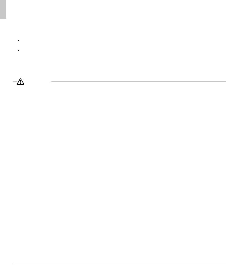
III BUTTONS
* means these units do not have these functions.
3.1 Silk Screen of Buttons
|
|
|
|
Fig.3.1 Silk screen of buttons |
|
|
|
|
|
|
3.2 Instruction to Function of Buttons |
|||
|
|
|
|
|
|
|
No. |
Description |
Function of Button |
|
|
|
|
|
|
|
1 |
Enter/Cancel |
(1) Function selection and canceling; |
|
(2) Press it for 5s to enquiry the outdoor ambient temperature.* |
|||
|
|
|
|
|
|
|
|
|
|
|
|
2 |
|
(1) Running temperature setting of indoor unit, range :16 30°C |
|
|
|
|
(2) Timer setting, range:0.5-24hr |
|
|
6 |
|
|
|
|
(3) Switchover between quiet/auto quiet |
||
|
|
|
|
|
|
|
3 |
Fan |
Setting of high/middle/low/auto fan speed |
|
|
|
|
|
|
|
4 |
Mode |
Setting of cooling/heating/fan/dry mode of indoor unit |
|
|
|
|
|
|
|
5 |
Function |
Switchover among the functions of air/sleep/turbo/save/E-heater/blow/ |
|
quiet |
|||
|
|
|
|
|
|
|
|
|
|
|
|
7 |
Timer |
Timer setting |
|
|
|
|
|
|
|
8 |
On/off |
Turn on/off indoor unit |
|
|
|
|
|
|
|
4 Mode |
|
Press them for 5s under off state of the unit to enter/cancel memory |
|
|
Memory |
function (If memory is set, indoor unit after power failure and then |
|
|
|
and |
power recovery will resume original setting state .If not, indoor unit is |
|
|
|
function |
||
|
|
2 |
defaulted to be off after power recovery. Memory function is defaulted to |
|
|
|
|||
|
|
|
|
be off before outgoing.) |
|
|
|
|
|
|
|
2 |
|
Upon startup of the unit without malfunction or under off state of the |
|
|
unit, press them at the same time for 5s into lock state. In this case, any |
||
|
|
and |
Lock |
|
|
|
other buttons won’t respond the press. Repress them for 5s to quit lock |
||
|
|
6 |
|
|
|
|
state. |
||
|
|
|
|
|
|
|
|
|
|
|
|
4 Mode |
Enquiry |
|
|
|
and setting |
Press them for 5s under unit off at the same time to set address. |
|
|
|
and |
||
|
|
of address of |
||
|
|
5 Function |
|
|
|
|
wired controller |
|
|
|
|
|
|
|
|
|
|
|
|
|
|
|
|
Table.3.1 |
8 |
English |
IV INSTALLATION OF WIRED CONTROLLER AND PROJECT DEBUGGING
4.1 Installation of Wired Controller
Fig.4.1 Sketch for Installation of Wired Controller
No. |
1 |
2 |
3 |
4 |
5 |
|
|
|
|
|
|
|
|
|
Socket’s base |
Soleplate of |
Screw M4X25 |
Front panel of |
Screw |
|
Description |
box installed in |
|||||
controller |
controller |
ST2.2X6.5 |
||||
|
the wall |
|
||||
|
|
|
|
|
||
|
|
|
|
|
|
Fig.4.1: Sketch for Installation of Wired Controller. Pay attention to the following items during installation of wired controller:
1.Cut off power supply of heavy-current wire embedded in mounting hole in the wall before installation. It is prohibited to perform the whole procedure with electricity.
2.Pull out 4-core twisted pair line in mounting hole and then make it through the rectangle hole at the back of controller’s soleplate.
3.Joint the controller’s soleplate on wall face and then fix it in mounting hole with screws M4X25.
4.Insert the 4-core twisted pair through rectangle hole into controller’s slot and buckle the front panel and soleplate of controller together.
5.At last, fix the controller’s front panel and soleplate with screws ST2.2X6.5.
CAUTION
During connection of wirings, pay special attention to the following items to avoid interference of electromagnetism to unit and even failure of it.
1.To ensure normal communication of the unit, signal line and wiring (communication) of wired controller should separate from power cord and indoor/outdoor connection lines. The distance between them should be kept 20cm in min.
2.If the unit is installed at the place where there is interference of electromagnetism, signal line and wiring (communication) of wired controller must be shielding twisted pair lines.
English |
9 |
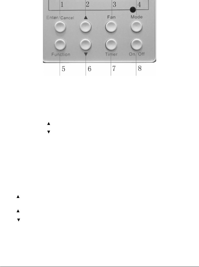
4.2 Project Debugging
Enquiry and Setting of Wired Controller’s Address
Enquiry of wired controller’s address: Press Function and Mode buttons at the same time for 5s under off state of the unit, and then LCD displays wired controller’s address number.
Setting of wired controller’s address: Press Function and Mode buttons at the same time for 5s.
In this case, LCD displays address number. Then press  or
or  button to adjust address (address no.:1-16). After that, press Enter/Cancel button to confirm.
Addresses of the wired controller are used for centralized control of wired controller. Enquiry and setting of wired controller’s address is shown as Fig.4.2 below:
Off state of unit |
Equipment address no. |
Press “Increase” or “Decrease” |
|
|
button to adjust |
Return to off state |
Press “Enter/Cancel” |
|
button to confirm |
Fig.4.2 Enquiry and Setting of Wired Controller’s Address
10 |
English |
V INSTRUCTION TO OPERATION
* means these units do not have these functions.
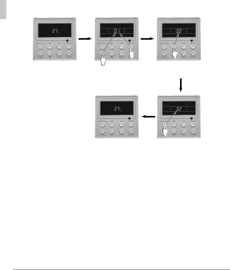
5.1 On/Off
Press On/Off button to turn on the unit.
Repress this button to turn off the unit.
Note:The state shown in Fig.5.1 indicates off state of the unit after energization. The state shown in Fig.5.2 indicates on state of the unit after energization.
Fig.5.1 Off state of the unit |
Fig.5.2 On state of the unit |
|
|
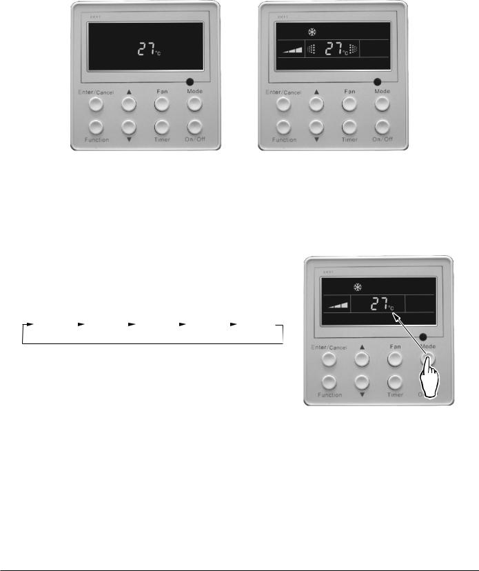
5.2 Mode Setting
Under on state of the unit, press Mode button to switch the operation modes as the following sequence:
Auto |
|
|
Cooling |
|
|
Dry |
|
|
Fan |
|
|
Heating |
|
|
|
|
|
|
|
|
|||||
|
|
|
|
|
|
|
|
|
|
|
|
|
English |
11 |
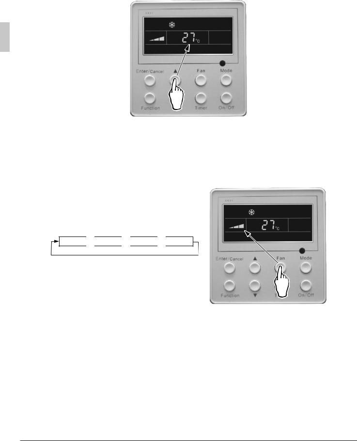
5.3 Temperature Setting
Press  or
or  button for increase or decrease of setting temperature under on state of the unit. If press either of them continuously, temperature will be increased or decreased by 1°C every 0.5s.
In Cooling, Dry, Fan and Heating mode, temperature setting range is 16 30°C. In Auto mode, the setting temperature is un-adjustable.
As shown in Fig.5.3
Fig.5.3
5.4 Fan Speed Setting
Under on/off state of the unit, press Fan button, fan speed of indoor unit will change as below: As shown in Fig.5.4
Auto 
 Low
Low 
 Middle
 High
High
Fig.5.4
12 |
English |
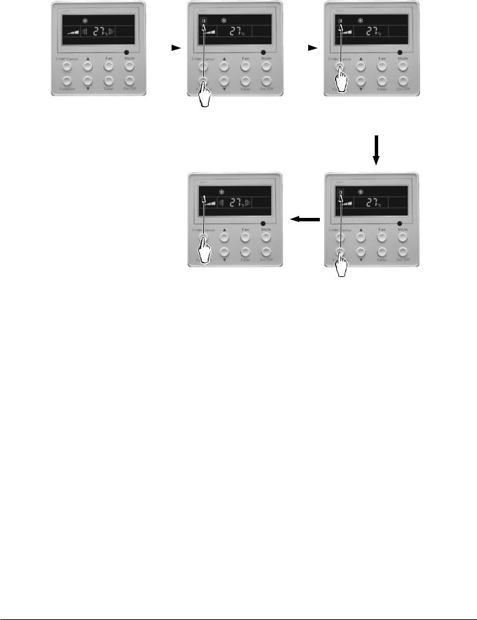
5.5 Swing Control Function
Under on state of unit, press Function button till the unit enters swing control function and then press Enter/ Cancel button to turn on turbo control function.
During swing function, press Function button till the unit enters swing control function and then press Enter/ Cancel button to cancel swing control function.
Swing control function setting is shown in Fig.5.5
Turn on the unit, without |
|
Press “Function” button |
|
Press “Enter/Cancel” button |
|
|
|
|
|||
|
|
|
|||
|
|
|
|||
turning on swing function |
|
into swing function |
|
to turn on swing function |
|
Press “Enter/Cancel” button |
Press “Function” button |
to turn off swing function |
into swing function |
Fig.5.5
5.6 Timer Setting
Under on state of the unit, press Timer button to set timer off of the unit. Under off state of the unit, press Timer button to set timer on of the unit in the same way.
Timer on setting: Under off state of the unit without timer setting, if Timer button is pressed, LCD will display xx. Hour, ON blinking. In this case, press  or
or  button to adjust timer on and then press Timer to confirm. If Mode button is pressed before pressing Timer button to confirm, timer mode will be switched to timer off setting mode. In this case, LCD displays xx. Hour, OFF blinking. In this case, pres
  or
or  button to adjust timer off and then press Timer to confirm. When LCD displays xx. Hour On Off, xx. Hour means time of timer on, but time of timer off won’t be displayed.
Timer off setting: Under on state of the unit without timer setting, if Timer button is pressed, LCD will display xx. Hour, OFF blinking. In this case, press  or
or  button to adjust timer on and then press Timer to confirm. If Mode button is pressed before pressing Timer button to confirm, timer mode will be switched to timer on setting mode. In this case, LCD displays xx. Hour, ON blinking. In this case, press
  or
or  button to adjust timer on and then press Timer button to confirm. When LCD displays xx. Hour On Off, xx. Hour means time of timer off, but time of timer on won’t be displayed.
Cancel timer: After setting of timer, if Timer button is pressed, LCD won’t display xx. Hour so that timer setting is canceled.
English |
13 |
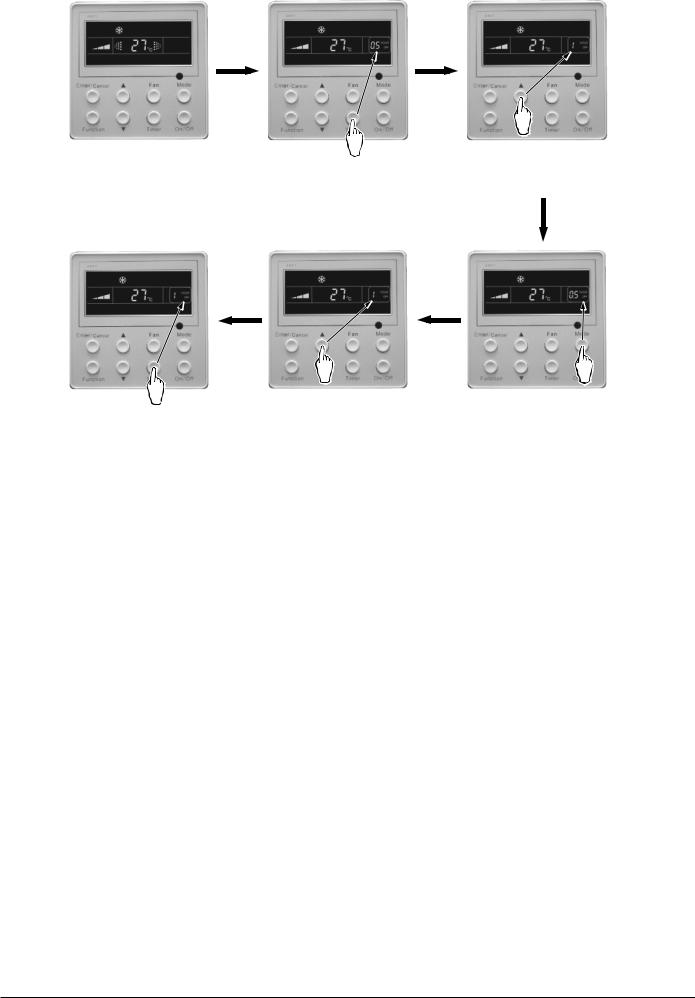
Timer off setting under on state of the unit is shown as Fig.5.6
|
Turn on the unit, without |
Press “Timer” to set |
Press “Increase” or “Decrease” |
|
setting timer |
|
button to adjust time |
|
|
|
|
Press “Timer” to confirm |
Press “Increase” or “Decrease” |
Press “Mode” button into |
timer setting |
button to adjust time |
timer on setting interface |
Fig.5.6 Timer setting under on state of the unit
Timer range: 0.5-24hr. Every press of  or
or  button will make setting time increased or decreased by 0.5hr. If press either of them continuously, setting time will automatically increase/decrease by 0.5hr every 0.5s.
Note:
1.If both timer on and timer off are set in unit on interface, the wired controller only display time of time off after confirmation of timer. If both of them are set in unit off interface, only time of timer on is displayed.
2.Timer on in unit on interface is timed from the time of unit off and timer off in unit off interface is timed from the time of unit on.
14 |
English |
Loading...