


Daikin EWAD-TZPLB, EWAD-TZPRB, EWAD-TZPSB, EWAD-TZSLB, EWAD-TZSRB User manual
...Installation, Operation and Maintenance Manual
D–EIMAC00907-16EN
Air cooled chiller with inverter driven screw compressor
EWAD~TZ
Refrigerant: R-134a
Original Instructions
D–EIMAC00907–16EN - 1/20
A
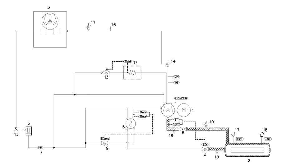
Typical refrigerant circuit - Water inlet and outlet are indicative. Please refer to the machine dimensional diagrams for exact water connections.
D–EIMAC00907–16EN - 2/20
B
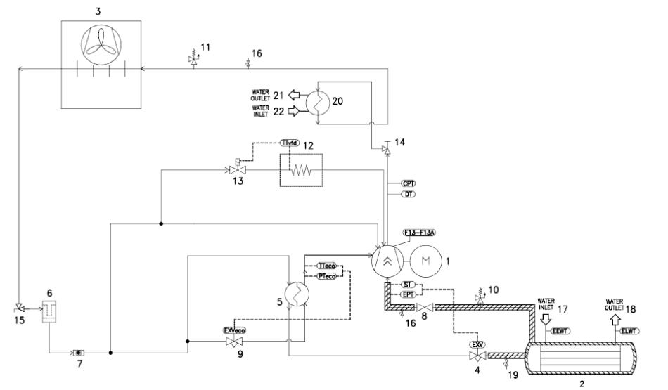
Typical refrigerant circuit with heat recovery - Water inlet and outlet are indicative. Please refer to the machine dimensional diagrams for exact water connections.
D-EIMAC00907-16EN - 3/20
|
Legend |
|
1 |
Compressor |
|
2 |
Evaporator |
|
3 |
Condenser coil & Axial fan |
|
4 |
Electronic expansion valve |
|
5 |
Economizer |
|
6 |
Dehydration filter |
|
7 |
Liquid and humidity indicator |
|
8 |
Sution valve |
|
9 |
Economizer electronic expansion |
|
valve |
||
|
||
10 |
Low-pressure safety valve |
|
11 |
High-pressure safety valve |
|
12 |
Heat exchanger (VFD cooling) |
|
13 |
Heat exchanger (VFD cooling) |
|
solenoid valve |
||
|
||
14 |
Discharge shut off valve |
|
15 |
Liquid line isolating valve |
|
16 |
¼” SAE Flare valve |
|
17 |
Evaporator water inlet connection |
|
18 |
Evaporator water outlet connection |
|
19 |
2 Way charging valve |
|
20 |
Heat Recovery (Optional) |
|
21 |
Heat Recovery water outlet |
|
connection |
||
|
||
22 |
Heat Recovery water inlet |
|
connection |
||
|
||
F13-F13A |
High pressure switch |
|
DT |
Discharge temperature sensor |
|
CPT |
Condenser pressure transducer |
|
EPT |
Evaporator pressure transducer |
|
ST |
Suction temperature sensor |
|
PTeco |
Economizer pressure transducer |
|
TTeco |
Economizer temperature |
|
transducer |
||
|
||
TTvfd |
VFD Temperature transducer |
|
EEWT |
Evaporator Entering Water |
|
Temperature probe |
||
|
||
ELWT |
Evaporator Leaving Water |
|
Temperature probe |
||
|
D-EIMAC00907-16EN - 4/20

This manual is an important supporting document for qualified personnel but it is not intended to replace such personnel.
Thank you for purchasing this chiller
READ THIS MANUAL CAREFULLY BEFORE INSTALLING AND STARTING UP THE UNIT. IMPROPER INSTALLATION COULD RESULT IN ELECTRIC SHOCK, SHORT-CIRCUIT, LEAKS, FIRE OR OTHER DAMAGE TO THE EQUIPMENT OR INJURE TO PEOPLE.
THE UNIT MUST BE INSTALLED BY A PROFESSIONAL OPERATOR/TECHNICIAN
UNIT STARTUP HAS TO BE PERFORMED BY AUTHORIZED AND TRAINED PROFESSIONAL
ALL ACTIVITIES HAVE TO BE PERFORMED ACCORDING TO LOCAL LAWS AND REGULATION.
UNIT INSTALLATION AND START UP IS ABOSOLUTELY FORBIDDEN IF ALL INSTRUCTION CONTAINED IN THIS MANUAL ARE NOT CLEAR.
IF CASE OF DOUBT CONTACT THE MANUFACTURER REPRESENTATIVE FOR ADVICE AND INFORMATION.
Description
The unit you bought is an “air cooled chiller”, a machine aimed to cool water (or water-glycol mixture) within the limits described in the following. The unit operation is based on vapour compression, condensation and evaporation according to reverse Carnot cycle. The main components are:
-Screw compressor to rise the refrigerant vapour pressure from evaporation pressure to condensation pressure
-Evaporator, where the low pressure liquid refrigerant evaporates to cool the water
-Condenser, where high pressure vapour condensate rejecting heat removed from the chilled water in the atmosphere thanks to an air cooled heat exchanger.
-Expansion valve allowing to reduced the pressure of condensed liquid from condensation pressure to evaporation pressure.
General Information
All units are delivered with wiring diagrams, certified drawings, nameplate; and DOC (Declaration Of Conformity); these documents show all technical data for the unit you have bought and they MUST BE
CONSIDERED ESSENTIAL DOCUMENTS OF THIS MANUAL
In case of any discrepancy between this manual and the equipment’s documents please refer to on board documents. In case of any doubt contact the manufacturer representative.
The purpose of this manual is to allow the installer and the qualified operator to ensure proper installation, commissioning and maintenance of the unit, without any risk to people, animals and/or objects.
Receiving the unit
The unit must be inspected for any possible damage immediately upon reaching final place of installation. All components described in the delivery note must be inspected and checked.
Should the unit be damaged, do not remove the damaged material and immediately report the damage to the transportation company and request they inspect the unit..
Immediately report the damage to the manufacturer representative, a set of photographs are helpful in recognizing responsibility
Damage must not be repaired before the inspection of the transportation company representative.
Before installing the unit, check that the model and power supply voltage shown on the nameplate are correct. Responsibility for any damage after acceptance of the unit cannot be attributed to the manufacturer.
Operating limits
Storing Storage
Environmental conditions must be within the following limits:
Minimum ambient temperature |
: |
-20°C |
Maximum ambient temperature |
: |
57°C |
Maximum R.H. |
: |
95% not condensing |
Storing below the minimum temperature may cause damage to components. Storing above the maximum temperature causes opening of safety valves. Storing in condensing atmosphere may damage electronic components.
Operation
Operation is allowed within the following limits:
Evaporator Leaving Water Temperature: 4…18°C (Cool Mode), -8…18°C (Cool with glycol, Ice Mode)
Outside Ambient Temperature @ full load:
Silver Efficiency Version: 10…47°C
Gold Efficiency Version: -18…50°C
Platinum Efficiency Version: -18…52°C
Operational envelope can be extended through selection of specific options (such as high ambient kit, brine version, etc) which allow the unit to operate down to -8°C evaporator leaving temperature and/or up to 52°C ambient temperature at full load.
The above mentioned values represent a guideline, please refer to the chiller selection software for real operating limits for the specific model.
As a general rule, The unit should be operated with an evaporator water flow rate between 50% and 140% of nominal flow rate (at standard operating conditions), however check with the chiller selection software the correct minimum and maximum allowed values for the specific model.
Operation out of the mentioned limits may damage the unit. In case of doubts contact manufacturer representative.
D–EIMAC00907–16EN - 5/20

Figure 1 - Description of the labels applied to the electrical panel
Single circuit unit
|
|
Double circuits unit |
||
Label Identification |
|
|
|
|
1 |
– Manufacturer’s logo |
|
5 |
– Cable tightening warning |
2 |
– Gas type |
|
6 |
– Non flammable gas symbol |
3 |
– Hazardous Voltage warning |
|
7 |
– Unit nameplate data |
4 |
– Electrical hazard symbol |
|
8 |
– Lifting instruction |
D-EIMAC00907-16EN - 6/20
 Loading...