


Daikin FBQ20EAVAK, FBQ24EAVAK, FBQ36EAVAK, FBQ45EAVAK, FBQ48EAVAK Installation manuals
...INSTALLATION MANUAL
ﺐﻴﻛﺮﺘﻟﺍ ﻞﻴﻟﺩ
English
SPLIT SYSTEM |
Air Conditioner |
|
ﺔﻴﺑﺮﻌﻟﺍ |
|
|
|
|
ﻢﺴﻘﻨﻤﻟﺍ ﻡﺎﻈﻨﻟﺍ |
ءﺍﻮﻬﻟﺍ ﻒﻴﻴﻜﺗ ﺯﺎﻬﺟ |
|
|
|
|
||
|
|
|
|
MODELS ﺯﺮﻄﻟﺍ |
|
|
|
(Ceiling mounted duct type) (ﻲﺋﺍﻮﻫ ﻯﺮﺠﻤﺑ ﺩﻭﺰﻣ ﻒﻘﺳ ﻒﻴﻴﻜﺗ) |
|
|
|
FBQ20EAVAK |
|
|
|
FBQ24EAVAK |
|
|
|
FBQ36EAVAK |
|
|
|
FBQ45EAVAK |
|
|
|
FBQ48EAVAK |
|
|
|
FBQ48EAVMK |
|
|
|
READ THESE INSTRUCTIONS CAREFULLY BEFORE INSTALLATION. KEEP THIS MANUAL IN A HANDY PLACE FOR FUTURE REFERENCE.
.ﺐﻴﻛﺮﺘﻟﺍ ﻞﺒﻗ ﺔﻳﺎﻨﻌﺑ ﺕﺍﺩﺎﺷﺭﻹﺍ ﻩﺬﻫ ﺃﺮﻗﺍ
.ﺪﻌﺑ ﺎﻤﻴﻓ ﻪﻴﻟﺇ ﻉﻮﺟﺮﻠﻟ ﻪﻴﻟﺇ ﻝﻮﺻﻮﻟﺍ ﻞﻬﺴﻳ ﻥﺎﻜﻣ ﻲﻓ ﻞﻴﻟﺪﻟﺍ ﺍﺬﻬﺑ ﻆﻔﺘﺣﺍ

FBQ20EAVAK
FBQ24EAVAK SPLIT SYSTEM Air Conditioner Installation manual FBQ36EAVAK
FBQ45EAVAK
FBQ48EAVAK
FBQ48EAVMK
|
CONTENTS |
|
1. |
SAFETY PRECAUTIONS............................................................................................... |
1 |
2. |
BEFORE INSTALLATION .............................................................................................. |
4 |
3. |
SELECTING INSTALLATION SITE................................................................................ |
6 |
4. |
PREPARATIONS BEFORE INSTALLATION ................................................................. |
7 |
5. |
INDOOR UNIT INSTALLATION ..................................................................................... |
9 |
6. |
REFRIGERANT PIPING WORK .................................................................................. |
10 |
7. |
DRAIN PIPING WORK ................................................................................................. |
13 |
8. |
DUCT WORK ............................................................................................................... |
15 |
9. |
ELECTRIC WIRING WORK ......................................................................................... |
16 |
10. |
WIRING EXAMPLE AND HOW TO SET THE REMOTE CONTROLLER.................... |
16 |
11. |
FIELD SETTING........................................................................................................... |
22 |
12. |
TEST OPERATION ...................................................................................................... |
25 |
1. SAFETY PRECAUTIONS
Please read the these " SAFETY CONSIDERATIONS" carefully before installing air conditioning unit and be sure to install it correctly. After completing the installation, make sure that the unit operates properly during the start-up operation.
Please instruct the customer on how to operate the unit and keep it maintained.
Also, inform customers that they should store this installation manual along with the operation manual for future reference.
Meaning of WARNING and CAUTION notices.
Both are important notices for safety. Be sure to follow them.
 WARNING .........Failure to follow these instructions properly may result in personal injury or loss of life.
 CAUTION ..........Failure to observe these instructions properly may result in property damage or personal injury, which may be serious depending on the circumstances.
After completing installation, conduct a trial operation to check for faults and explain to the customer how to operate the air conditioner and take care of it with the aid of the operation manual. Ask the customer to store the installation manual along with the operation manual for future reference.
This air conditioner comes under the term “appliances not accessible to the general public”.

 WARNING
•Ask your dealer or qualified personnel to carry out installation work.
Do not attempt to install the air conditioner yourself. Improper installation may result in water leakage, electric shocks or fire.
•Install the air conditioner in accordance with the instructions in this installation manual. Improper installation may result in water leakage, electric shocks or fire.
•When installing the unit in a small room, take measures against to keep refrigerant concentration from exceeding allowable safety limits in the event of refrigerant leakage.
Contact the place of purchase for more information. Excessive refrigerant in a closed ambient can lead to oxygen deficiency
•Be sure to use only the specified accessories and parts for installation work.
Failure to use the specified parts may result in the unit falling, water leakage, electric shocks or fire.
1 |
English |

•Install the air conditioner on a foundation strong enough to withstand the weight of the unit. A foundation of insufficient strength may result in the equipment falling and causing injury.
•Carry out the specified installation work after taking into account strong winds, typhoons or earthquakes. Failure to do so during installation work may result in the unit falling and causing accidents.
•Make sure that a separate power supply circuit is provided for this unit and that all electrical work is carried out by qualified personnel according to local laws and regulations and this installation manual.
An insufficient power supply capacity or improper electrical construction may lead to electric shocks or fire.
•Be sure to earth the air conditioner.
Do not earth the unit to a utility pipe, lightning conductor or telephone earth lead. Imperfect earthing may result in electric shocks or fire.
A high surge current from lightning or other sources may cause damage to the air conditioner.
•Be sure to install the earth leakage breaker.
Failure to install the earth leakage breaker may result in electric shocks or fire.
•Be sure to switch off the unit before touching any electrical parts. Touching a live part may result in electric shock.
•Make sure that all wiring is secured, the specified wires are used, and that there is no strain on the terminal connections or wires.
Improper connections or securing of wires may result in abnormal heat build-up or fire.
•When wiring the power supply and connecting the wiring between the indoor and outdoor units, position the wires so that the control box lid can be securely fastened.
Improper positioning of the control box lid may result in electric shocks, fire or overheating terminals.
•If refrigerant gas leaks during installation, ventilate the area immediately. Toxic gas may be produced if the refrigerant comes into contact with fire.
•After completing installation, check for refrigerant gas leakage.
Toxic gas may be produced if the refrigerant gas leaks into the room and comes into contact with a source of fire, such as a fan heater, stove or cooker.
•Do not touch any refrigerant that leaks out of refrigerant piping joints or connections. Touching it may cause frostbite.
•Consult your local dealer regarding what to do in case of refrigerant leakage, when the air coditioner is to be installed in a small room, it is necessary to take proper measures so that the amount of any leaked refrigerant does not exceed the concentration limit in the event of leakage. Otherwise, this may lead to an accident due to oxygen depletion.

 CAUTION
•While following the instructions in this installation manual, install drain piping to ensure proper drainage and insulate piping to prevent condensation.
Improper drain piping may result in indoor water leakage and property damage.
•Install the indoor and outdoor units, power cord and connecting wires at least 1 meter away from televisions or radios to prevent picture interference and noise.
(Depending on the incoming signal strength, a distance of 1 meter may not be sufficient to eliminate noise.)
•Install the indoor unit as far away from fluorescent lamps as possible.
Remote controller (wireless kit) transmitting distance can be shorter than expected in rooms with electronic fluorescent lamps (inverter or rapid start types).
•In a domestic environment this product may cause radio interference in which case the user may be required to take adequate measures.
•Do not allow children to climb on the outdoor unit and avoid placing objects on the unit. Injury may result if the unit becomes loose and falls.
•Make sure to provide for adequate measure in order to prevent that the outdoor unit be used as a shelter by small animals.
Small animals making contact with electrical parts can cause malfunctions, smoke or fire. Please instruct the customer to keep the area around the unit clean.
•Install in a machine room that is free of moisture. The unit is designed for indoor use.
•Disposal requirements
Dismantling of the unit, treatment of the refrigerant, of oil and of other parts must be done in accordance with relevant local and national legislation.
English |
2 |

•Do not install the air conditioner in the following locations:
1.Where there is a high concentration of mineral oil spray or vapour (e.g. a kitchen). Plastic parts will deteriorate, parts may fall off and water leakage could result.
2.Where corrosive gas, such as sulphurous acid gas, is produced. Also areas that are rich in sodium such as seashores.
Corroding of copper pipes or soldered parts may result in refrigerant leakage.
3.Near machinery emitting electromagnetic radiation.
Electromagnetic radiation may disturb the operation of the control system and result in a malfunction of the unit.
4.Where flammable gas may leak, where there is carbon fibre or ignitable dust suspensions in the air, or where volatile flammables such as paint thinner or gasoline are handled.
Operating the unit in such conditions may result in fire.
SPECIAL NOTICE OF PRODUCT
• Refrigerant
•The refrigerant R410A requires that strict Precautions be observed for keeping the system clean, dry and tightly sealed.
A. Clean and Dry
Strict measure must be taken to keep impurities (including SUNISO oil and other mineral oils as well as moisture) out of the system.
B. Tightly sealed
R410A contains no chlorine, does not destroy the ozone layer and so does not reduce the earth’s protcetion against harmful ultraviolet radiation. R410A will contribute only slightly to the greenhouse effect if released into the almosphere
•Since design pressure is 4.0 MPa or 40 bar (for R407C units: 3.3MPa or 33bar), the thickness of pipes must be greater than previously. Since R410A is a mixed refrigerant, the required additional refrigerant must be charged in its liquid state. (If the system is charged with refrigerant in its gaseous state, due to composition change, the system will not function normally). The indoor units is designed for R410A use.
See the catalogue for indoor unit models that can be connected. (Normal operation is not possible when connecting units that are originally designed for other refrigerants)
3 |
English |
2. BEFORE INSTALLATION
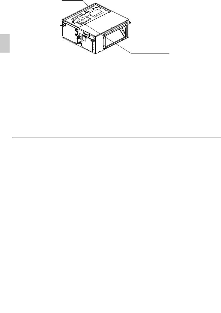
Do not exert pressure on the resin parts when opening the unit or when moving it after opening. Be sure to check the type of R410A refrigerant to be used before doing any work. (Using an incorrect refrigerant will prevent normal operation of the unit.)
•When opening the unit or moving it after opening, be sure to lift it by holding on to the lifting lugs without exerting any pressure on other parts, especially, drain piping, and flange.
•Decide upon a line of transport.
•Leave the unit inside its packaging while moving, until reaching the installation site. Use a sling of soft material, where unpacking is unavoidable or protective plates together with a rope when lifting, to avoid damage or scratches to the unit.
•Refer to the installation manual of the outdoor unit for items not described in this manual.
•Do not dispose of any parts necessary for installation until the installation is complete.
•In order to protect the indoor unit from damage, use packing materials to protect the unit after carrying until the installation starts.
•Do not use the unit in locations with high salt content in the air such as beachfront property, locations where the voltage fluctuates such as factories, or in automobiles or marine vessels.
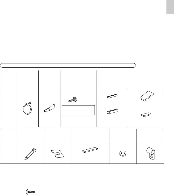
2-1 ACCESSORIES
Check the following accessories are included with your unit. Refer to Fig. 1 for the location of the accessories.
Do not dispose of any parts necessary for installation until the installation is completed.
Name |
Metal clamp |
Drain hose |
Screws for duct |
Insulation for |
Sealing pad |
|
(1) |
(2) |
flanges (3) |
fitting |
|||
|
|
|||||
|
|
|
|
|
|
|
Quantity |
1 pc. |
1 pc. |
As described in table |
1 each |
– |
|
below |
||||||
|
|
|
|
|
|
|
|
M5×16 |
|
|
Thin |
|
1 pc. |
|
|
|
|
for liquid pipe (4) |
|
|||
Shape |
|
20 • 24 type |
18 |
|
||||
|
Large (Dark gray) (6) |
|||||||
|
|
|
||||||
|
|
36 • 45 • 48 type |
26 |
|
|
|
|
|
|
|
|
|
|
|
Thick |
|
2 pcs. |
|
|
|
|
|
for gas pipe (5) |
|
||
|
|
|
|
|
|
|
Middle (Dark gray) (7) |
|
Name |
Clamp (8) |
Washer fixing |
Wire sealing material |
Washer (11) |
Wire fixing |
|||
plate (9) |
(10) |
|
bracket (12) |
|||||
|
|
|
|
|
||||
Quantity |
9 pcs. |
4 pcs. |
2 pcs. |
|
8 pcs. |
|
2 pcs. |
|
Shape
Small (Gray)
Name |
Wire fixing screw |
|
(13) |
|
|
|
|
|
|
|
(Other) |
Quantity |
2 pcs. |
|
|
|
• Operation manual |
|
|
|
Shape |
M4×8 |
• Installation manual |
|
|
|
|
|
|
|
|
|
English |
4 |
|
(1) - (13)
Operation manual |
|
Installation manual |
Fig. 1 |
|
2-2 OPTIONAL ACCESSORIES
•The optional remote controller are required for this indoor unit.
•These are two types of remote controllers: wired and wireless. Select a remote controller according to customer request and install in an appropriate place.
(When installing, follow the instructions in the manual included with the remote controller.)
|
Remote controller |
|
|
|
|
Wired type |
|
BRC1C61 / BRC1D61 / BRC1E62 |
|
|
|
Wireless type |
|
BRC4C62 |
|
|
|
• BRC4C62 cannot be used for the indoor unit FBQ48EAVMK. If required, use wireless type BRC4C64
FOR THE FOLLOWING ITEMS, TAKE SPECIAL CARE DURING CONSTRUCTION AND CHECK AFTER INSTALLATION IS FINISHED.
a. Items to be checked after completion of work
Items to be checked |
If not properly done, what is likely to occur |
Check |
|
|
|
Are the indoor unit and outdoor unit fixed |
The unit may drop, vibrate or make noise. |
|
firmly? |
|
|
|
|
|
|
|
|
Is the outdoor unit fully installed? |
The unit may malfunction or components |
|
burn out. |
|
|
|
|
|
|
|
|
Is the gas leak test finished? |
It may result in insufficient cooling or |
|
heating. |
|
|
|
|
|
|
|
|
Is the unit fully insulated? (Refrigerant pip- |
Condensate water may drip. |
|
ing, drain piping, and duct) |
|
|
|
|
|
|
|
|
Does drainage flow smoothly? |
Condensate water may drip. |
|
|
|
|
Does the power supply voltage correspond |
The unit may malfunction or the |
|
to that shown on the name plate? |
components burn out. |
|
|
|
|
Are wiring and piping correct? |
The unit may malfunction or the |
|
components burn out. |
|
|
|
|
|
|
|
|
Is the unit safely grounded? |
It may result in electric shock. |
|
|
|
|
Is wiring size according to specifications? |
The unit may malfunction or the |
|
components burn out. |
|
|
|
|
|
|
|
|
Is something blocking the air outlet or inlet |
|
|
of either the indoor or outdoor units? |
It may result in insufficient cooling or |
|
(This can lead to malfunction or decreased |
heating. |
|
performance due to decreased air volume.) |
|
|
|
|
|
Does the cold air (warm air) blow properly |
It may result in insufficient cooling or |
|
during the cooling (heating) operation? |
heating. |
|
|
|
|
Are refrigerant piping length and additional |
The refrigerant charge in the system is not |
|
refrigerant charge noted down? |
clear. |
|
|
|
|
Has the field setting done (as necessary)? |
It may result in insufficient cooling or |
|
heating. |
|
|
|
|
|
|
|
|
5 |
English |

Did you set the external static pressure? |
It may result in insufficient cooling or |
|
heating. |
|
|
|
|
|
|
|
|
Did you check that no wiring connection |
Electric shock or fire. |
|
screws were loose? |
|
|
|
|
|
|
|
|
b.Items to be checked at time of delivery
*Also review the “1. SAFETY PRECAUTIONS”
Items to be checked |
Check |
|
|
Did you attach the control box lid, the air filter, air inlet grille and air outlet grille? |
|
|
|
Did you explain about operations while showing the instruction manual to your customer? |
|
|
|
Did you hand the instruction manual over to your customer? |
|
|
|
Did you explain the customer the handling and cleaning methods of the field supplies |
|
(e.g., the air filter, air inlet grilles, and air outlet grille)? |
|
|
|
Did you deliver instruction manual, if any, for the field supplies to the customer? |
|
|
|
Points for explanation about operations
The items with  WARNING and
  CAUTION marks in the instruction manual are the items pertaining to possibilities for bodily injury and material damage in addition to the general usage of the product. Accordingly, it is necessary that you make a full explanation about the described contents and also ask your customers to read the instruction manual.
2-3 NOTE TO THE INSTALLER
•Be sure to instruct customers how to properly operate the unit (especially cleaning filters, operating different functions, and adjusting the temperature) by having them carry out operations themselves while looking at the manual.
3. SELECTING INSTALLATION SITE
•When opening the unit or moving it after opening, be sure to lift it by holding on to the hanger bracket without exerting any pressure on other parts, especially piping (refrigerant piping and drain piping) and other resin parts.
•Please attach additional thermal insulation material to the unit body when it is believed that the relative humidity in the ceiling exceeds 80%.
•Use glass wool, polyethylene foam, or similar with a thickness of 10 mm or more as thermal insulation material.
(1)Select an installation site where the following conditions are fulfilled and that meets your customer’s approval.
•Where optimum air distribution can be ensured.
•Where nothing blocks air passage.
•Where condensate can be properly drained.
•Where the ceiling is strong enough to bear the indoor unit weight.
•Where the false ceiling is not noticeably on an incline.
•Where sufficient clearance for maintenance and service can be ensured. (Refer to Fig. 2)
•Where there is no risk of flammable gas leakage.
•Where piping between indoor and outdoor units is possible within the allowable limit. (Refer to the installation manual for the outdoor unit.)

 CAUTION
•The indoor and outdoor units and the power supply wiring and remote controller cord must be installed at least 1m away from any televisions or radios. This is to prevent interference with picture and sound reception. (Interference may occur even at 1m away depending on the reception quality.)
•If installing the wireless kit, the distance of the signal sent from the remote controller might be shorter if there are fluorescent lights which are electrically started (such as with inverters, rapid starters, etc.) in the room. The indoor unit should be installed as far away from fluorescent lights as possible.
English |
6 |
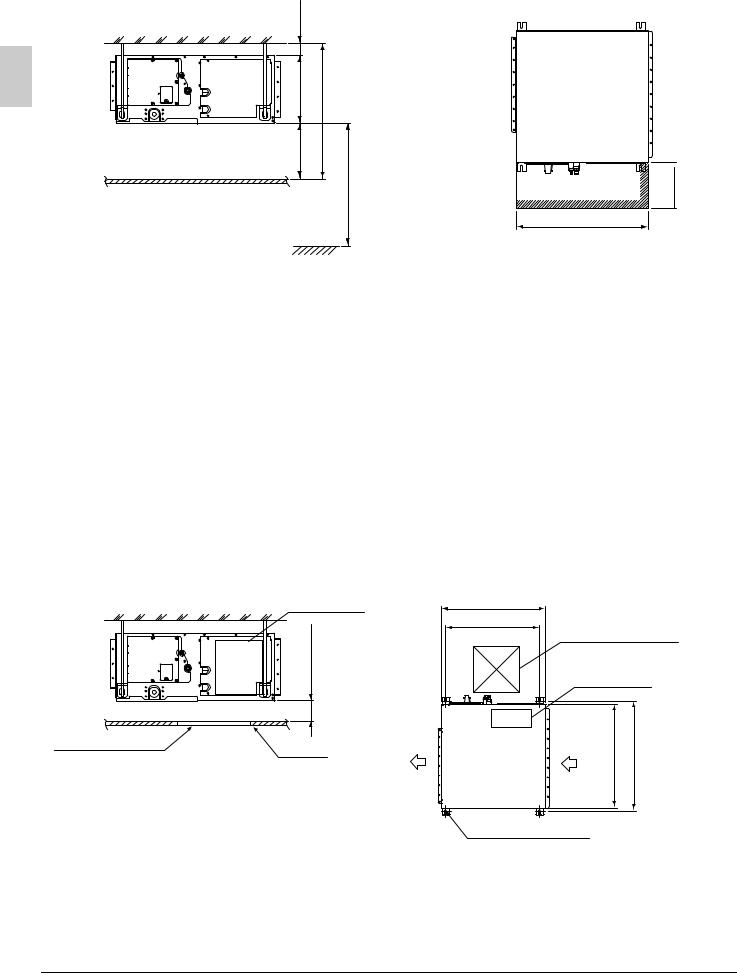
(2)Use suspension bolts for installation. Check if the location for the installation is strong enough to support the weight of the unit, reinforce it if necessary, and install using suspension bolts.
|
<![if ! IE]> <![endif]>Min. 20 |
|
|
|
<![if ! IE]> <![endif]>*H1=300 |
<![if ! IE]> <![endif]>*H2=Min. 620 |
<![if ! IE]> <![endif]>provided.) |
Ceiling |
<![if ! IE]> <![endif]>Min. 300 |
<![if ! IE]> <![endif]>Min. 2500 |
<![if ! IE]> <![endif]>ceiling board is |
|
|||
|
Floor surface |
<![if ! IE]> <![endif]>(If no |
|
*The H1 dimension indicates the height of the product.
*Determine the H2 dimension by maintaining
a downward slope of at least 1/100 as |
|
specified in “7. DRAIN PIPING WORK”. |
Fig. 2 |
|
(length: mm)
<![if ! IE]><![endif]>Min. 450
Min. 700 (service space)
[Required installation place]
The dimensions indicate the minimum required space of installation.
4. PREPARATIONS BEFORE INSTALLATION
(1)Check the positional relationship between the ceiling opening hole and the hanging bolt of the unit.
•For the maintenance, inspection, and other servicing purposes of the control box, prepare one of the following service spaces.
1.Inspection hatch 1 (450 × 450) for the control box and a minimum space of 300 mm for the lower part of the product. (Refer to Fig. 3)
2.Inspection hatch 1 (450 × 450) for the control box and inspection hatch 2 for the lower part of the product (see axial direction view A-1). (Refer to Fig. 4)
3.Inspection hatch 3 for the lower part of the product and the lower part of the control box (see axial direction view A-2). (Refer to Fig. 4)
Case 1
Inspection hatch
Control box
<![if ! IE]><![endif]>*H3=Min. 300
Ceiling Air outlet
Fig. 3
700 |
Inspection hatch 1 |
|||
631 |
||||
(450×450) |
|
|||
(Hanging bolt pitch) |
|
|||
|
Control box |
|||
|
|
|
<![if ! IE]> <![endif]>pitch) |
|
Bottom of unit |
<![if ! IE]> <![endif]>B |
<![if ! IE]> <![endif]>C |
<![if ! IE]> <![endif]>(Hangingbolt |
|
|
|
|||
Air inlet
Hanging bolt (× 4)
7 |
English |
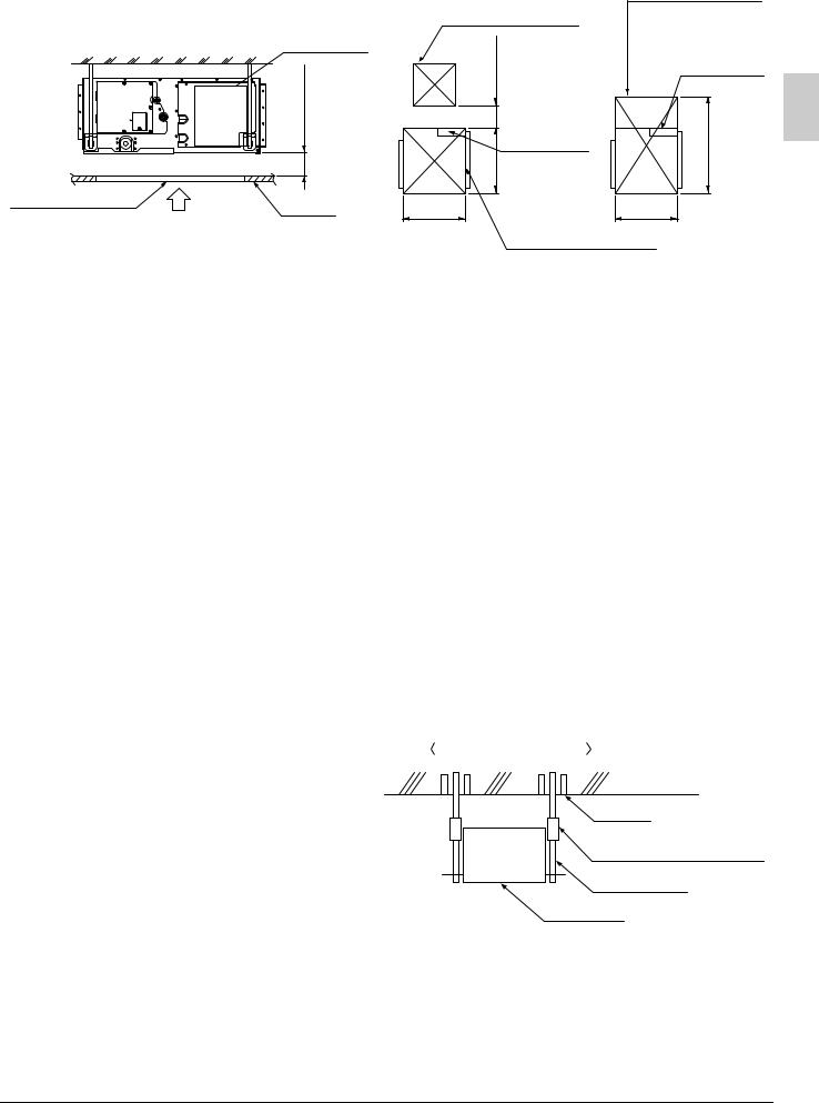
Case 2, 3
Inspection hatch (Ceiling opening)
Inspection hatch |
A |
|
Control box
| <![if ! IE]> <![endif]>*H3=Min. 20 |
Ceiling
Inspection hatch 1 (450×450)
<![if ! IE]><![endif]>Min. 200
Control box
<![if ! IE]><![endif]>B
700
Inspection hatch 3 (Same as the indoor unit size +300 or more)
Control box
<![if ! IE]><![endif]>Min. D=B+300
700
*Determine the H3 dimension by maintaining a downward slope of at least 1/100 as specified in “7. DRAIN PIPING WORK”.
Inspection hatch 2 (Same as the indoor
|
|
unit size or more) |
|
|
|||||
Axial direction view A-1 |
|
|
Axial direction view A-2 |
||||||
|
|
|
|
|
|
|
|
|
|
|
|
|
|
|
|
|
|
|
|
|
|
|
Fig. 4 |
|
|
|
|||
|
|
|
|
|
|
|
|
|
|
|
|
Model |
|
B |
|
C |
D |
|
|
|
20 |
• 24 type |
|
1000 |
1038 |
1300 |
|
|
|
|
36 |
• 45 • 48 type |
|
1400 |
1438 |
1700 |
(length: mm) |
||
(2)Mount the canvas ducts to the air outlet and inlet so that the vibration of the air conditioner will not be transmitted to the duct or ceiling. Apply a sound-absorbing material (insulation material) to the inner wall of the duct and vibration insulation rubber to the hanging bolts (refer to 8. DUCT WORK).
(3)Open installation holes (if the ceiling already exists).
•Open the installation holes on the ceiling. Lay the refrigerant piping, drain piping, power line, transmission wiring, and remote controller wiring for the piping and wiring connection port of the unit. In the case of the installation of a wireless remote controller, refer to the installation manual provided with the wireless remote controller.
Refer to 6. REFRIGERANT PIPING WORK, 7. DRAIN PIPING WORK, and 10. WIRING EXAMPLE AND HOW TO SET THE REMOTE CONTROLLER.
•The ceiling framework may need reinforcement in order to keep the ceiling horizontal and prevent the vibration of the ceiling after the installation holes are opened. For details, consult your construction or interior contractor.
(4)Install the hanging bolts. Make sure that the hanging bolts are M10 in size.
•Use hole-in anchors if the hanging bolts already exist; otherwise use embedded inserts and embedded foundation bolts so that they will withstand the weight of the unit. Adjust the distance to the ceiling surface in advance.
Installation example
Ceiling slab
Anchor
Long nut or turn-buckle Hanging bolt
Indoor unit
Note) All the above parts are field supplied.
English |
8 |
5. INDOOR UNIT INSTALLATION
It may be easier to install accessories (sold separately) before installing the indoor unit. Refer to the installation manuals provided to the accessories as well.
As for the parts to be used for installation work, be sure to use the provided accessories and specified parts designated by our company.
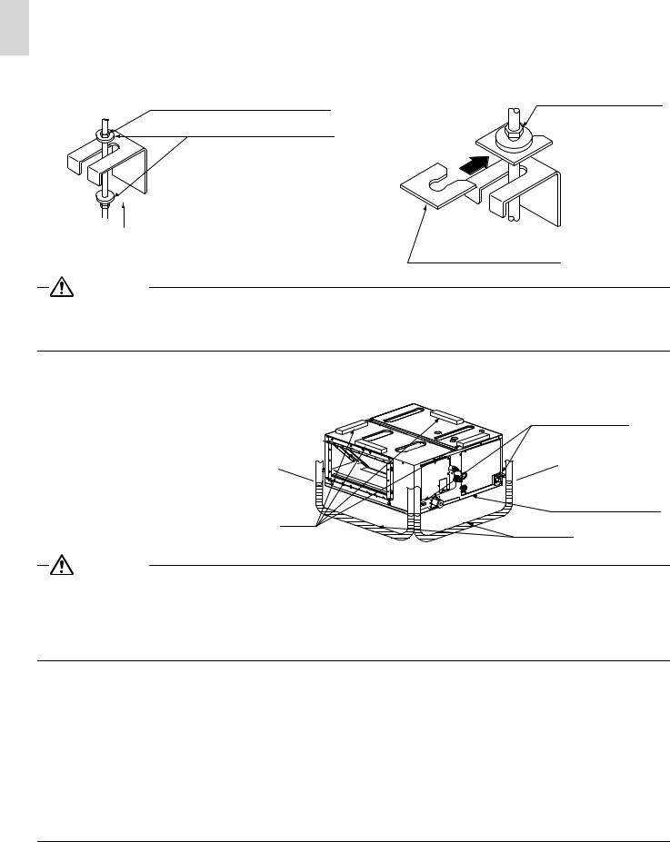
(1)Temporally install the indoor unit.
•Connect the hanging brackets to the hanging bolts. Be sure to use and tighten the nut and washer (11) for each hanging bracket from both upper and lower sides of the hanging bracket. (Refer to Fig. 5) At that time, the fall of the washer (11) for the hanging bracket can be prevented if the washing fixing plate (9) is used.
[Fixing hanging brackets] |
|
[Fixing method of washers] |
Part to be procured in the field |
Nut on the upper side |
|
|
||
Washer |
(11) (accessory) |
|
|
|
Insert |
Tighten from above and below |
|
|
(Double nut) |
|
Washer fixing plate (9) |
|
Fig. 5 |
(accessory) |
|
|
CAUTION
•During the installation work, perform the curing of the air outlet and protect the resin drain pan of the indoor unit from the intrusion of foreign substances, such as welding spatters.
Otherwise, water leakage may occur as a result of damage, such as hole damage, to the resin drain pan.
(2)Make adjustments so that the unit will be in the right position.
(3)Check the level of the unit.
(4)Remove the washer fixing plates for
the falling prevention of the washers |
|
Hanging bracket |
for the hanging brackets, tighten the |
|
|
nuts on the upper side, and securely |
|
|
fix the unit. |
|
|
|
Level |
Bottom of product |
|
Vinyl tube |
|
|
|
CAUTION
•Use the level and check that the unit is installed horizontally. (4-directions)
•In the case of using a vinyl tube in place of the level, put the both edges of the vinyl tube in close contact with the bottom of the product to make levelness adjustment.
If the unit is installed at a slant with the drain pipe side set high, in particular, the float switch will not operate normally and water leakage may result.
9 |
English |
6. REFRIGERANT PIPING WORK
For refrigerant piping of outdoor units, see the installation manual attached to the outdoor unit.
Execute heat insulation work completely on both sides of the gas piping and the liquid piping. Otherwise, a water leakage can result sometimes.
(When using a heat pump, the temperature of the gas piping can reach up to approximately 120°C, so use insulation which is sufficiently resistant.)
Also, in cases where the temperature and humidity of the refrigerant piping sections might exceed 30°C or RH80%, reinforce the refrigerant insulation. (20mm or thicker) Condensate may form on the surface of the insulating material.
Be sure to check the type of R410A refrigerant to be used before doing any work. (Using an incorrect refrigerant will prevent normal operation of the unit.)

 CAUTION
This product is designed to be used with new refrigerant (R410A). Always observe the precautions on the following when installing.
•Use a pipe cutter and flare suitable for the type of refrigerant.
•Apply ester oil or ether oil around the flare section before connecting.
•Use the flare nut provided to the unit. Do not use a different flare nut (class 1), or otherwise refrigerant leakage may result.
•To prevent dust, moisture or other foreign matter from infiltrating the tube, either pinch the end or cover it with tape.
•Do not allow anything other than the designated refrigerant to get mixed into the refrigerant circuit, such as air, etc. If any refrigerant gas leaks while working on the unit, ventilate the room thoroughly right away.
•The outdoor unit is charged with refrigerant.
•Be sure to use both a spanner and torque wrench together, as shown in the drawing, when connecting or disconnecting pipes to/from the unit.
(Refer to Fig. 6)
•Refer to “Table 1” for the dimensions of flare nut spaces.
•Use the flare nut included with the unit main body.
•When connecting the flare nut, apply ester oil or ether oil to the flare section (inside only), and spin 3-4 times before screwing in.
(Refer to Fig. 7)

 CAUTION
Torque wrench
Spanner |
|
Flare nut |
|
Piping union |
Fig. 6 |
Coat here with ester or etheroil. |
|
Fig. 7
•Do not let oil get on the screw holders on the dressing board. Oil can weaken the screw holders.
•Refer to “Table 1” to determine the proper tightening torque.
•Be careful not to damage the flare section.
English |
10 |
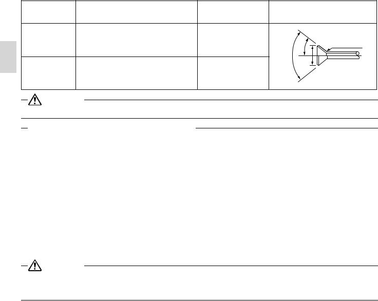
Table 1
|
Pipe size |
Tightening torque (N·m) |
Flare dimensions |
|
Flare |
|
A (mm) |
|
|||
|
|
|
|
|
|
|
φ 9.5 (3/8”) |
32.7 – 39.9 |
12.8 – 13.2 |
2˚ |
R0.4-0.8 |
|
± |
||||
|
|
|
<![if ! IE]> <![endif]>2˚ |
45˚ |
|
|
|
|
<![if ! IE]> <![endif]>± |
|
|
|
|
|
<![if ! IE]> <![endif]>90˚ |
|
<![if ! IE]> <![endif]>A |
|
φ 15.9 (5/8”) |
61.8 – 75.4 |
19.3 – 19.7 |
|
|
|
CAUTION |
|
|
|
|
• |
Over-tightening the flare nut may break it and/or cause the refrigerant to leak. |
|
|
||
Not recommendable but in case of emergency
You must use a torque wrench but if you are obliged to install the unit without a torque wrench, you may follow the installation method mentioned below.
After the work is finished, make sure to check that there is no gas leak.
When you keep on tightening the flare nut with a spanner, there is a point where the tightening torque suddenly increases. From that position, further tighten the flare nut the angle shown below:
Unless followed the tightening instruction (it is loose tightening), it will lead to the refrigerant leakage (slow leak) and the device malfunction (it does not sufficiently cool or heat).
|
Pipe size |
Further tightening angle |
Recommended arm length of tool |
|
|
|
|
|
φ 9.5 (3/8”) |
60 to 90 degrees |
Approx. 200mm |
|
|
|
|
|
φ 15.9 (5/8”) |
30 to 60 degrees |
Approx. 300mm |
|
|
|
|
|
|
|
|
CAUTION
For local insulation, be sure to insulate local piping all the way into the pipe connections inside the machine.
Exposed piping may cause condensation or burns on contact.
•Make absolutely sure to execute heat insulation works on the pipe-connecting section after checking gas leakage by thoroughly studying the following figure and using the attached heat insulating materials for fitting (4) and (5). (Fasten both ends with the clamps (8).) (Refer to Fig. 8)
•Wrap the middle sealing material (7) around the insulation for fitting (4) and (5) for the joint (flare nut part).
•Make sure that the joint of the insulation for fitting (4) and (5) for the joint on the liquid piping and gas piping side faces upward.
11 |
English |

Heat insulation procedure for liquid piping
Insulation for fitting (4) (accessory)
Insulation material for piping |
Flare nut joint |
|
|
||
(on unit side) |
Make sure that the seam faces upward. |
|
|
||
Attached to the surface. |
Middle sealing pad (7) (accessory) |
|
|
||
Main unit |
|
|
Clamp (8) (accessory) |
|
|
|
Wrap the insulation material around the |
|
Insulation material for piping (field supply) |
portion from the surface of the main unit |
|
to the upper part of the flare nut joint. |
||
|
Liquid pipe
Gas pipe
Fig. 8
Heat insulation procedure for gas piping
Insulation for fitting (5) (accessory)
Insulation material for piping (on unit side)
Attached to the surface.
Clamp (8) (accessory)
Insulation material for piping (field supply)
Flare nut joint
Make sure that the seam faces upward.
Middle sealing pad (7) (accessory)
Wrap the insulation material around the portion from the surface of the main unit to the upper part of the flare nut joint.
•When brazing the refrigerant piping, only begin brazing after having carried out nitrogen substitution or while inserting nitrogen into the refrigerant piping.
Once this is done, connect the indoor unit with a flared or a flanged connection.
|
Pressure-reducing valve |
Refrigerant piping |
Taping |
Part to be |
|
brazed |
Hands valve |
|
|
Nitrogen |
Nitrogen |
|
Fig. 9
English |
12 |
•Nitrogen should be set to 0.02MPa with a pressure-reducing valve if brazing while inserting nitrogen into the piping. (Refer to Fig. 9)
•Do not use flux when brazing refrigerant piping. Therefore, use the phosphor copper brazing filler metal (BCuP-2: JIS Z 3264/B-Cu93P-710/795: ISO 3677) which does not require flux.
(Flux has extremely harmful influence on refrigerant piping systems. For instance, if the chlorine based flux is used, it will cause pipe corrosion or, in particular, if the flux contains fluorine, it will damage the refrigerant oil.)
•When the airtight test is performed for the indoor unit and inter-unit piping after indoor unit installation, be sure to refer to the installation manual for the indoor unit or technical guide for airtight pressurization and refrigerant piping installation.
•Shortage of refrigerant due to air purge or losing the additional refrigerant charging may cause the failure of the unit (does not sufficiently cool or heat).
Be sure to refer the installation manual or the engineering guide for the outdoor unit at the refrigerant piping work.

 CAUTION
•Do not use anything such as the oxidation inhibitor when brazing. (Residues may result in the clogging pipe or parts damage.)
7. DRAIN PIPING WORK
(1)Remove the drain socket cover. (for transportation)
(2)Conduct drain piping work.
Check that the piping ensures proper draining.
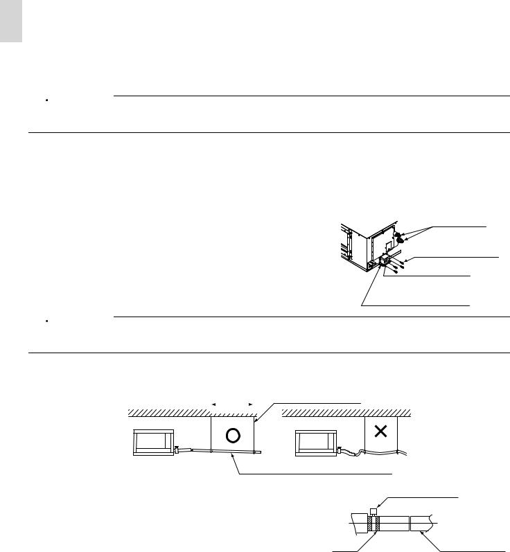
•Make sure that the diameter of the piping excluding the rising part is the same as or larger than the diameter of the connecting pipe (vinyl chloride pipe with an outer diameter of 32 mm and a nominal inner diameter of 25 mm).
•Make sure that the piping is short enough with a downward slope of at least 1/100 and that there is no air bank formed. No drain trap is required.

 CAUTION
Refrigerant piping
Screw (4 portions)
Drain socket
Drain socket cover (for transportation)
•The drain piping will be clogged with water and water leakage may result if the water is accumulated in the drain piping.
•Conduct drain-up piping work if the gradient is insufficient.
•Attach some support brackets at 1 to 1.5 m intervals for the prevention of piping deflection.
1 - 1.5 m |
Supporting hanger |
||
|
|
|
|
Downward slope of at least 1/100
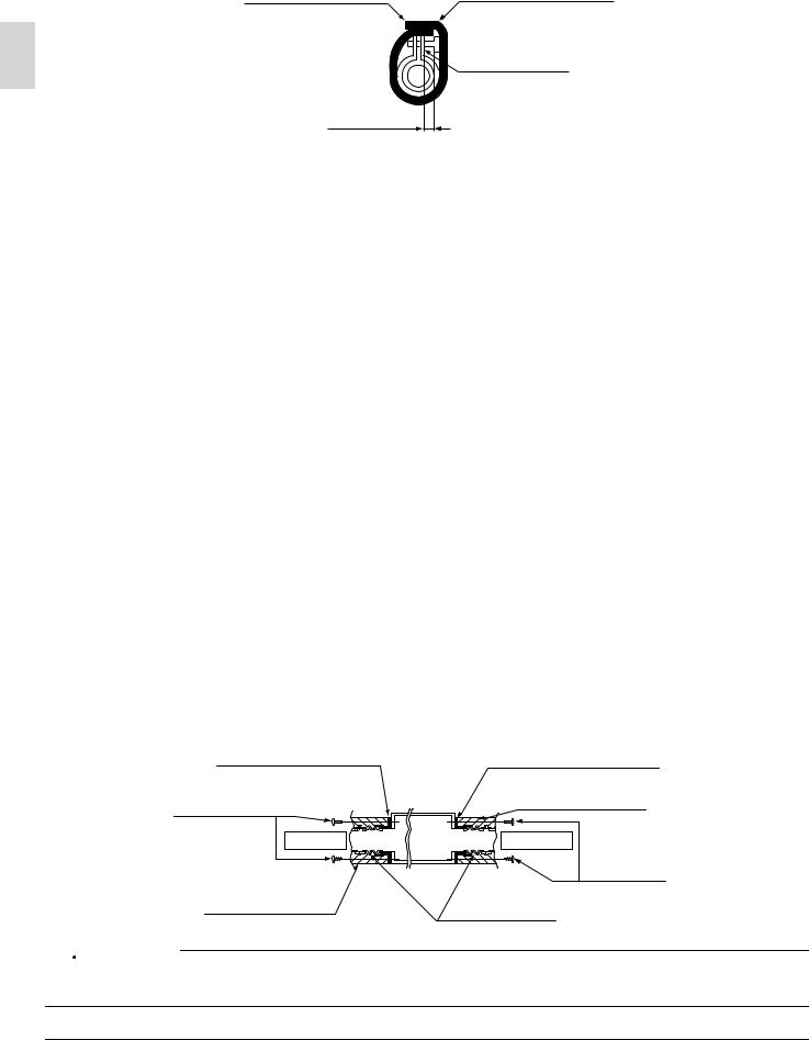
•Be sure to use the drain hose (2) and metal clamp (1).
Insert the drain hose (2) deep into the base of the drain socket, and securely fasten the metal clamp (1) within the taped part on the insertion front end of the hose.
Be sure to fasten the screw of the metal clamp (1) until the |
Tape |
margin of the screw thread decreases to 4 mm or less. |
Metal clamp (1) (accessory)
Drain hose (2) (accessory)
|
|
|
13 |
English |
|
NOTE

Be sure to follow the instructions as below.
•Do not connect the drain piping directly to a sewer that smells of ammonia.
The ammonia in the sewer may reach through the drain piping and corrode the heat exchanger of the indoor unit.
•Do not bend or twist the provided drain hose (2) in order not to impose excessive force on the hose. (Doing so may result in water leakage.)
•Take the procedure shown in the following illustration to perform concentrated drain piping.
<![endif]>Min. 100 mm
Concentrated drain piping
Maintain a downward slope of at least 1/100 so that no air bank will be formed.
The drain piping will be clogged with water and water leakage may result if the water is accumulated in the drain piping.
•Select the diameter of the concentrated drain piping to suit the capacity of equipment connecting to the concentrated drain piping (see the equipment design sheet).
Ceiling slab
1 - 1.5 m  Support bracket
Metal clamp (1) (accessory)
Drain hose (2) (accessory)
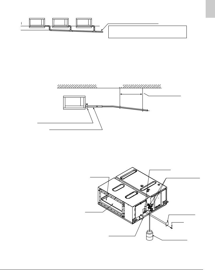
(3)Check the smooth draining of the piping on completion of the installation of the piping.
•Provide approximately one liter of water gradually into the drain pan through the water inlet on the bottom of the drain socket or the outlet.
(4)Be sure to conduct heat insulation work on the following portions, or otherwise water leakage may occur as a result of dew condensation.
• |
Drain piping indoors |
Water inlet |
|
• |
Drain socket |
||
|
|||
|
Drain pan |
Refrigerant piping |
Air outlet |
Water inlet lid |
|
|
|
Screw |
Drain socket |
Plastic water |
|
container |
English |
14 |
•On completion of the drainage check, refer to the following illustration, and use the provided large sealing pad (6) and heat insulate the metal clamp (1) and drain hose (2).
Make sure that the
seam faces upward. Large sealing pad (6) (accessory)
Metal clamp (1) (accessory)
4 mm max.
8. DUCT WORK
Pay the utmost attention to the following items and conduct the ductwork.
•Check that the duct will not be in excess of the setting range of external static pressure for the unit. (Refer to the technical datasheet for the setting range.)
•Attach a canvas duct each to the air outlet and air inlet so that the vibration of the equipment will not be transmitted to the duct or ceiling.
Use a sound-absorbing material (insulation material) for the lining of the duct and apply vibration insulation rubber to the hanging bolts.
•At the time of duct welding, perform the curing of the duct so that the sputter will not come in contact with the drain pan for the filter.
•If the metal duct pass through a metal lath, wire lath, or metal plate of a wooden structure, separate the duct and wall electrically.
•Be sure to heat insulate the duct for the prevention of dew condensation. (Material: Glass wool or styrene foam; Thickness: 25 mm)
•Be sure to attach the field supply air filter to the air inlet of the unit or field supply inlet in the air passage on the air suction side. (Be sure to select an air filter with a duct collection efficiency of 50 weight percent.)
•Explain the operation and washing methods of the locally procured components (i.e., the air filter, air inlet grille, and air outlet grille) to the customer.
•Locate the air outlet grille on the indoor side for the prevention of drafts in a position where indirect contact with people.
•The air conditioner incorporates a function to adjust the fan to rated speed automatically. (11. FIELD SETTING) Therefore, do not use booster fans midway in the duct.
Connection method of ducts on air inlet and outlet sides.
•Connect the field supply duct in alignment with the inner side of the flange.
•Connect the flange and unit with the flange connection screw (3).
•Wrap aluminum tape around the flange and duct joint in order to prevent air leakage.
Flange on air inlet side (provided with the unit)
Flange on air outlet side (provided with the unit)
Screws for duct |
|
|
Insulation material |
|
flanges (3) |
|
|
(field supply) |
|
(accessory) |
Air inlet |
Unit |
Air outlet |
Screws |
|
for duct |
|||
|
|
|
|
|
Insulation material |
|
|
flanges (3) |
|
|
Canvas duct |
(accessory) |
||
(field supply) |
|
|||
|
(field supply) |
|
||
|
|
|
|
|

 CAUTION
Connect the flange and unit with the flange connection screw (3) regardless of whether the duct is connected to the air inlet side.
15 |
English |
9. ELECTRIC WIRING WORK
WIRING INSTRUCTIONS
•Electric wiring work must be conducted by electrician authorized by power companies. (Only licensed electrician can conduct electric work and earth connections.)
•All wiring must be performed by an authorized electrician.
•Be sure to install an earth leakage breaker to the outdoor unit.
(This installation of an earth leakage breaker is mandatory for the prevention of electric shocks and fire disasters.)
•Install the earth leakage breaker which can handle harmonics.
(This unit has an inverter, so an interrupter capable of handling high frequencies is needed to prevent malfunction of the interrupter itself.)
•Be sure to use earth leakage breaker dedicated for earth leakage protection in combination with the load break switch with fuse or breaker for wiring.
•Make sure that 230V is specified wiring between the indoor and outdoor units and between indoor units.
•Do not turn on the power supply (of the indoor unit) until all the installation work is completed.
•Be sure to earth the air conditioner.
•Do not connect the earth wire to gas pipes, plumbing pipes, lightning rods, or telephone earth wires.
•Gas pipes: might cause explosions or fire if gas leaks.
•Plumbing: no earth effect if hard vinyl piping is used.
•Telephone earth wires or lightning rods: might cause abnormally high electric potential in the earth during lighting storms.
•The earth is needed in order to reduce the noise generated by the unit’s inverter and influence on other appliances and to release the charge built up in the product box by leaked current.
•For electric wiring work, refer to also “WIRING DIAGRAM” attached to the unit body.
•Never connect the power supply wire to the terminal block for remote controller wire, or otherwise the entire system may be damaged.
•For remote controller wiring details, refer to the installation manual attached to the remote controller.
•Do not touch the printed circuit board ASSY during the wiring work. Otherwise, it may cause damage.
10. WIRING EXAMPLE AND HOW TO SET THE REMOTE CONTROLLER
10-1 Connection of wiring between units, earth wire and for the remote controller cord
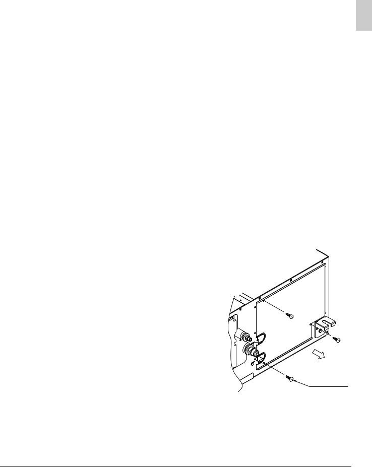
(Remove the control box lid as shown below and connect each wire.)
(1) Remove the control box lid.
Screw
(3 portions)
English |
16 |
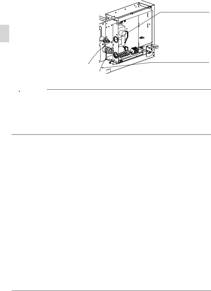
(2)Lay the wires in the control box through the wire inlet on the side of the control box.

 CAUTION
Low-voltage wiring inlet
• Remote controller wiring (Low voltage)
High-voltage wiring inlet
• Wiring the units (High voltage)
•Power supply wiring (High voltage)
•Ground wiring (High voltage)
•Do not lay the remote controller wiring along with the wiring the units, power supply wiring or other electric wiring in the same route. Separate the remote controller wiring at least 50 mm from the wiring the units, power supply wiring or other electric wiring, or otherwise malfunctions or failures may be caused by external electric noise that may interfere with the remote controller wiring.
•For the installation and wiring of the remote controller, refer to the remote controller installation manual provided with the remote controller.
•For wiring the units, power supply wiring, refer to the wiring diagram as well.
•Be sure to connect the remote controller wiring correctly to the right terminal block (X2M).
17 |
English |
 Loading...