


Daikin FHC20JEV1K, RD20JEV1K, FHC25JEV1K, RD25JEV1K, FHC30JEV1K Installation manuals
...INSTALLATION
MANUAL
CEILING CASSETTE
R22 SPLIT TYPE AIR CONDITIONER
Installation Manual |
English |
|
R22 Split Type Air Conditioner |
||
|
||
|
|
MODELS
FHC20JEV1K RD20JEV1K
FHC25JEV1K RD25JEV1K
FHC30JEV1K RD30JEV1K
FHC40JEV1K RD40JEV1K
RD40JEY1K
FHC50JEV1K RD50JEY1K
IM-CKE-0412(0)-DAIKIN
Part No.: R08019037616

|
|
|
OUTLINE AND DIMENSIONS |
|
|
|
|
|
|
||||
Indoor Unit |
|
|
|
|
|
|
|
|
|
|
|
|
|
|
B |
|
|
|
C |
|
|
|
F |
|
|
|
|
|
|
|
|
|
|
|
|
|
|
|
|
||
|
|
|
|
|
D |
E |
|
|
H |
|
|
|
|
|
|
|
|
|
|
|
|
|
|
|
|
|
|
|
|
|
|
|
|
|
|
K |
|
|
|
|
|
| <![if ! IE]> <![endif]>A |
|
|
|
|
|
|
|
|
|
|
|
<![if ! IE]> <![endif]>J I G |
|
|
|
|
|
|
|
|
|
|
All dimensions are in mm |
||||
Dimension |
A |
B |
C |
D |
|
E |
F |
G |
H |
|
I |
J |
K |
Model |
|
|
|||||||||||
|
|
|
|
|
|
|
|
|
|
|
|
|
|
FHC20JEV1K |
|
|
|
|
|
|
|
|
|
|
|
|
|
FHC25JEV1K |
820 |
820 |
340 |
300 |
|
40 |
990 |
990 |
627 |
|
627 |
607 |
430 |
FHC30JEV1K |
|
|
|
|
|
|
|
|
|
|
|
|
|
FHC40JEV1K |
820 |
820 |
375 |
335 |
|
40 |
990 |
990 |
627 |
|
627 |
607 |
430 |
FHC50JEV1K |
|
|
|||||||||||
|
|
|
|
|
|
|
|
|
|
|
|
|
|
Outdoor Unit |
|
|
|
|
|
|
|
|
|
|
|
|
|
|
L |
|
K |
|
|
L |
|
|
All dimensions are in mm |
||||
|
|
|
|
|
|
|
<![if ! IE]> <![endif]>N |
|
|||||
|
|
|
|
|
|
|
|
|
|
|
|
|
|
|
|
|
|
|
|
|
<![if ! IE]> <![endif]>M |
|
|
|
|
|
|
|
|
|
|
|
|
|
<![if ! IE]> <![endif]>Q |
|
|
|
|
|
|
|
|
|
A |
|
|
|
<![if ! IE]> <![endif]>N |
|
|
C |
|
|
|
|
|
|
|
|
|
|
|
G |
|
H |
|
|
|
|
O |
|
D |
|
|
|
|
<![if ! IE]> <![endif]>F |
|
|
|
||
|
|
|
|
|
|
|
|
|
|
|
|||
|
|
|
|
|
|
|
|
|
|
|
|
||
|
|
|
|
|
|
|
|
<![if ! IE]> <![endif]>E |
|
|
|
|
|
| <![if ! IE]> <![endif]>B |
|
|
|
|
|
|
|
|
|
|
|
|
|
|
|
|
|
|
|
|
<![if ! IE]> <![endif]>S |
|
|
|
|
|
|
|
|
|
|
|
|
|
<![if ! IE]> <![endif]>R |
|
|
|
|
|
|
| <![if ! IE]> <![endif]>P |
|
|
|
|
|
|
|
|
|
I |
J |
|
|
Dimension |
A |
B |
C |
D |
E |
F |
G |
H |
I |
|
J |
K |
L |
Model |
|
||||||||||||
|
|
|
|
|
|
|
|
|
|
|
|
|
|
RD20JEV1K |
855 |
628 |
328 |
520 |
179 |
46 |
93 |
149 |
101 |
|
113 |
603 |
126 |
RD25JEV1K |
855 |
730 |
328 |
520 |
179 |
46 |
93 |
149 |
101 |
|
113 |
603 |
126 |
RD30JEV1K |
|
||||||||||||
|
|
|
|
|
|
|
|
|
|
|
|
|
|
Dimension |
M |
N |
O |
P |
Q |
R |
S |
|
|
|
|
|
|
Model |
|
|
|
|
|
|
|||||||
|
|
|
|
|
|
|
|
|
|
|
|
|
|
RD20JEV1K |
164 |
15 |
34 |
23 |
362 |
73 |
75 |
|
|
|
|
|
|
RD25JEV1K |
164 |
15 |
34 |
23 |
362 |
73 |
75 |
|
|
|
|
|
|
RD30JEV1K |
|
|
|
|
|
|
|||||||
|
|
|
|
|
|
|
|
|
|
|
|
|
|
|
|
|
|
|
1 |
|
|
|
|
|
|
|
|
<![endif]>Original Instruction English

Outdoor Unit
J I J
<![endif]>N M N
All dimensions are in mm
A
K |
|
|
|
|
D |
|
|
|
|
|
|
|
|
|
|
|
|
|||||||||
|
|
|
|
|
|
|
|
|
|
|
|
|
|
|
|
|
|
|
|
|
|
|
|
|
|
|
|
|
|
|
|
|
|
|
|
|
|
|
|
|
|
|
|
|
|
|
|
|
|
|
|
|
|
|
|
|
|
|
|
|
|
|
|
|
|
|
|
|
|
|
|
|
|
|
|
|
|
|
|
|
|
|
|
|
|
|
|
|
|
|
|
|
|
|
|
|
|
|
|
|
|
|
|
|
|
|
|
|
|
|
|
|
|
|
|
|
|
|
|
|
|
|
|
|
|
|
|
|
|
|
|
|
|
|
|
|
|
|
|
|
|
|
|
|
|
|
|
|
|
|
|
|
|
|
|
|
|
|
|
|
|
|
|
|
|
|
|
|
|
|
|
|
|
|
|
|
|
|
|
|
|
|
|
|
|
|
|
|
<![endif]>B
| <![if ! IE]> <![endif]>F |
| <![if ! IE]> <![endif]>L |
<![if ! IE]> <![endif]>E |
|
|
Dimension |
A |
B |
C |
D |
E |
F |
G |
|
Model |
||||||||
|
|
|
|
|
|
|
||
RD40JEV1K |
|
|
|
|
|
|
|
|
RD40JEY1K |
1030 |
826 |
400 |
410 |
57 |
72 |
90 |
|
RD50JEY1K |
|
|
|
|
|
|
|
|
O |
|
C |
|
|
|
|
|
|
|
G |
H |
|
|
|
H |
I |
J |
K |
L |
M |
N |
O |
40 |
746 |
142 |
60 |
26 |
448 |
22 |
28 |
2
INSTALLATION MANUAL
This manual provides the procedures of installation to ensure a safe and good standard of operation for the air conditioner unit.
Special adjustment may be necessary to suit local requirements.
Before using your air conditioner, please read this instruction manual carefully and keep it for future reference. This appliance is intended to be used by expert or trained users in shops, in light industry and on farms, or for commercial use by lay persons.
This appliance is not intended for use by persons, including children, with reduced physical, sensory or mental capabilities, or lack of experience and knowledge, unless they have been given supervision or instruction concerning use of the appliance by a person responsible for their safety.
Children should be supervised to ensure that they do not play with the appliance.
SAFETY PRECAUTIONS
!WARNING
•Installation and maintenance should be performed by qualified persons who are familiar with local code and regulation, and experienced with this type of appliance.
•All field wiring must be installed in accordance with the national wiring regulation.
•Ensure that the rated voltage of the unit corresponds to that of the name plate before commencing wiring work according to the wiring diagram.
•The unit must be GROUNDED to prevent possible hazard due to insulation failure.
•All electrical wiring must not touch the refrigerant piping, or any moving parts of the fan motors.
•Confirm that the unit has been switched OFF before installing or servicing the unit.
•Disconnect from the main power supply before servicing the air conditioner unit.
•DO NOT pull out the power cord when the power is ON. This may cause serious electrical shocks which may result in fire hazards.
•Keep the indoor and outdoor units, power cable and transmission wiring, at least 1m from TVs and radios, to prevent distorted pictures and static. {Depending on the type and source of the electrical waves, static may be heard even when more than 1m away}.
! CAUTION
Please take note of the following important points when installing.
•Do not install the unit where leakage of flammable gas may occur.
If gas leaks and accumulates around the unit, it may cause fire ignition.
•Ensure that the drainage piping is connected properly.
If the drainage piping is not connected properly, it may cause water leakage which will dampen the furniture.
• Do not overcharge the unit.
This unit is factory pre-charged. Overcharge will cause over-current or damage to the compressor.
•Ensure that the unit’s panel is closed after service or installation.
Unsecured panels will cause the unit to operate noisily.
•Sharp edges and coil surfaces are potential locations which may cause injury hazards. Avoid from being in contact with these places.
•Before turning off the power supply, set the remote controller’s ON/OFF switch to the “OFF” position to prevent the nuisance tripping of the unit. If this is not done, the unit’s fans will start turning automatically when power resumes, posing a hazard to service personnel or the user.
•Do not install the units at or near doorway.
•Do not operate any heating apparatus too close to the air conditioner unit or use in room where mineral oil, oil vapour or oil steam exist, this may cause plastic part to melt or deform as a result of excessive heat or chemical reaction.
•When the unit is used in kitchen, keep flour away from going into suction of the unit.
•This unit is not suitable for factory used where cutting oil mist or iron powder exist or voltage fluctuates greatly.
•Do not install the units at area like hot spring or oil refinery plant where sulphide gas exists.
•Ensure the color of wires of the outdoor unit and the terminal markings are same to the indoors respectively.
•IMPORTANT : DO NOT INSTALL OR USE THE AIR CONDITIONER UNIT IN A LAUNDRY ROOM.
•Don’t use joined and twisted wires for incoming power supply.
•The equipment is not intended for use in a potentially explosive atmosphere.
<![endif]>English
3
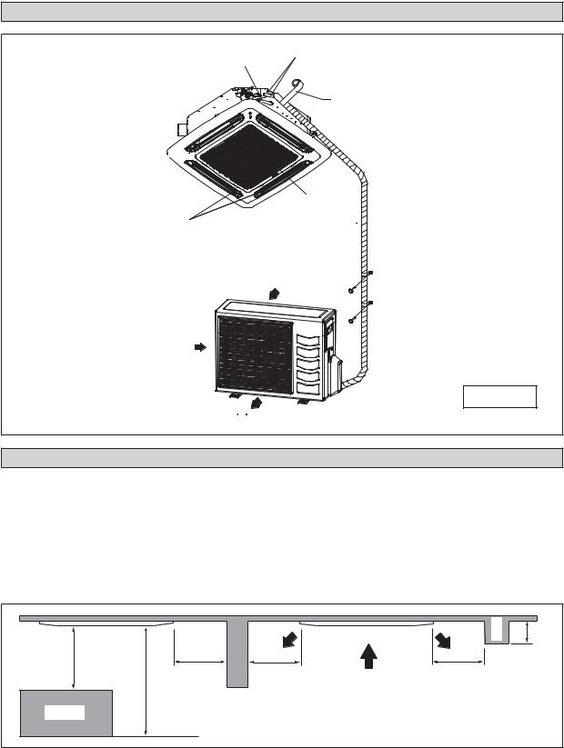
INSTALLATION DIAGRAM
Indoor Unit |
Drain Piping |
Thermal Insulation |
|
||
|
|
|
Front Panel 

Air Filter  (behind the grille)
Air Discharge Louver
Air Intake
Wrap the insulated pipe with the Ànishing tape from bottom to top
Air Intake Grille
Air Intake
Outdoor Unit
Air Discharge
INSTALLATION OF THE INDOOR UNIT
Preliminary Site Survey
Be sure to read this manual before installing the air-conditioner indoor unit.
•Voltage supply Áuctuation must not exceed +10% of rated voltage. Electricity supply lines must be independent of welding transformers which can cause high supply Áuctuation.
•Ensure that the location is convenient for wiring, piping and drainage.
•Do not exert pressure on the resin parts when opening the unit or when moving it after opening.
•Do not move the unit from packaging while moving, until it reaches the installation site. Use safe material or protection plates when unpacking it or lifting it to avoid damage or scratches to the unit.
| <![if ! IE]> <![endif]>more1mor |
<![if ! IE]> <![endif]>more |
0.5m or more |
0.5m or more |
0.5m or more |
<![if ! IE]> <![endif]>less0.3mor |
|
|
<![if ! IE]> <![endif]>Beam |
|||
|
<![if ! IE]> <![endif]>3m or |
|
|
|
|
Obstacle |
|
|
|
|
|
|
|
Floor |
|
|
|
4
• Ensure a location where: |
|
||
a) |
Drainage can be done easily. |
<![if ! IE]> <![endif]>English |
|
b) |
Convenient for wiring and piping. |
||
|
|||
c) |
Which have enough space for installation and service work. |
|
|
d) |
Where no risk of flammable gas leakage. |
|
|
e) |
When free from any obstacles in path of cool air discharge and warm air return and must allow spreading of air |
|
|
f) |
throughout the room (near the center of the room). |
|
|
|
|||
Must be provided clearance for indoor unit from the wall and obstacles as shown in figure below. |
|
||
g) |
The installation place must be strong enough to support a load 4 times the indoor unit weight to avoid amplifying |
|
|
|
noise and vibration. |
|
|
h) |
The installation place (hanging ceiling surface) must be assuring levelness and the height in the ceiling is 350mm or |
|
|
|
more. |
|
|
i) |
The indoor unit must be away from heat and steam sources (avoid installing it near an entrance). |
|
|
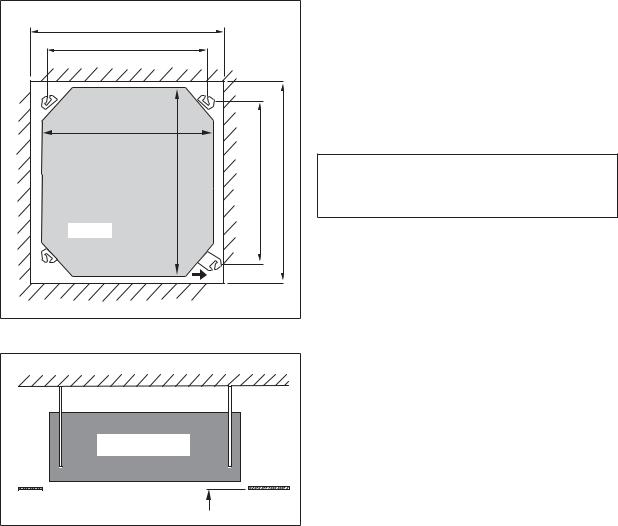
Unit Installation
Ceiling Opening Site = 890mm |
|
|
|
Hanging Rod Site = 790mm |
|
|
|
Unit size 820mm |
|
|
<![if ! IE]> <![endif]>= 890mm |
|
|
<![if ! IE]> <![endif]>621mm |
|
Unit |
<![if ! IE]> <![endif]>Unit size 820mm |
<![if ! IE]> <![endif]>Hanging rod size = |
<![if ! IE]> <![endif]>Ceiling Opening Site |
|
|
Piping Direction |
|
•Measure and mark the position for the hanging rod. Drill the hole for the angle nut on the ceiling and fix the hanging rod.
•The installation template is extended according to temperature and humidity. Check on dimensions in use.
•The dimensions of the installation template are the same as those of the ceiling opening dimensions.
•Before ceiling laminating work is completed, be sure to fit the installation template to the indoor unit.
NOTE
Be sure to discuss the ceiling drilling work with the installers concerned.
Unit Hanging
Indoor Unit |
Ceiling |
Board |
30 mm |
•Confirm the pitch of the hanging rod is 770mm x 622mm sharp.
•Hold the unit and hang it on the hanging rod with the nut and washer.
•Adjust the unit height to 30mm between the indoor unit bottom surface and the ceiling surface.
•Confirm with a level gauge that the unit is installed horizontally and tighten the nut and bolt to prevent unit falling and vibration.
•Open the ceiling board along the outer edge of the paper installation template.
5
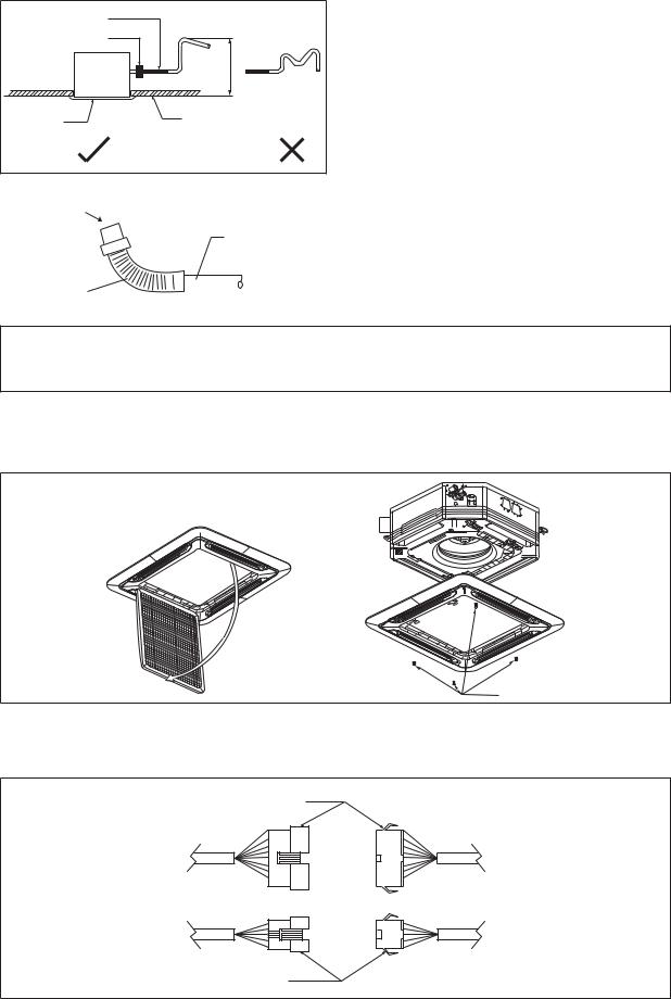
Drain Piping Work
|
Flexible Hose |
|
|
Pipe Clamp |
|
|
|
<![if ! IE]> <![endif]>or less |
|
Indoor |
<![if ! IE]> <![endif]>700.0mm |
|
Unit |
|
|
|
|
Panel |
|
Ceiling |
Drain Test
•Avoid installing the drain pipe in upward gradient after the drain connection.
•Ensure the height of drain pipe from ceiling is 700mm or less if it is necessary to increase the height of drain pipe to prevent water leak.
•Avoid installing the drain pipe in up and down slope to prevent reversed water flow.
•During the drain pipe connection, be careful not to exert extra force on the drain connector at indoor unit.
•The outside diameter of the drain connection at the flexible drain hose is 20mm.
•Be sure to execute heat insulation (polyethylene foam with thickness more than 8mm) on the drain piping to avoid the condensed water dripping inside the room.
Feed Water |
|
|||||
|
|
|
Main Drain Pipe |
• Connect the main drain pipe to the flexible drain hose. |
||
|
|
|
|
|
• Feed water from flexible drain hose to check the piping |
|
|
|
|
|
|
for leakage. |
|
|
|
|
|
|
• When the test is completed, connect the flexible drain |
|
|
|
|
|
|
||
|
|
|
|
|
hose to the drain connector on the indoor unit. |
|
Flexible Drain Hose |
||||||
|
||||||
|
|
|
|
|
|
|
NOTE
This Indoor Unit uses a drain pump for condensed water drainage. Install the unit horizontally to prevent water leakage or condensation around the air outlet.
Panel Installation
•The front panel can only be fitted in one direction, follow the piping direction. (Follow piping arrow sticker on front panel)
•Be sure to remove the installation template before installing the front panel.
Open
Screw
•Open the air intake grille by pulling back the catchers and removing it together with filter from panel.
•Install the front frame panel onto the indoor unit by 4 screws and tighten it completely to prevent cool air leakage.
•Connect the LED wire and air swing wire to the indoor unit.
•The air swing connector must put inside the control box after connected.
LED Wire
From Front |
From Unit |
Panel |
Control Box |
Air Swing Wire
6
 Loading...