


ERLQ018BAVJU

INSTALLATION MANUAL
Outdoor unit for air to water heat pump
ERLQ018BAVJU
ERLQ024BAVJU
ERLQ030BAVJU
Installation manual
Outdoor unit for air to water heat pump
Manuel d’installation
Unité extérieure pour pompe à chaleur air à eau
Manual de instalación
Unidad exterior para bomba de calor de aire-agua
English
Français
Español
ERLQ018BAVJU
ERLQ024BAVJU
ERLQ030BAVJU
Outdoor unit for air to water heat pump
Installation manual
C
ONTENTS
1. Definitions.................................................................................. 1
2. Introduction................................................................................ 2
2.1. General information........................................................................ 2
2.2. Model identification ........................................................................ 2
2.3. Combination and options ............................................................... 2
2.4. Operation range ............................................................................. 2
In cooling mode.............................................................................. 2
In heating mode ............................................................................. 2
In domestic water heating mode .................................................... 2
3. Accessories ............................................................................... 3
4. General safety precautions........................................................ 3
5. Overview of unit......................................................................... 3
5.1. Opening the unit............................................................................. 3
5.2. Main components........................................................................... 3
Unit................................................................................................. 3
Switchbox....................................................................................... 4
5.3. Functional diagram......................................................................... 4
6. Precautions on installation location ........................................... 4
6.1. General precautions....................................................................... 4
6.2. Weather dependent precautions.................................................... 5
6.3. Selecting a location in cold climates .............................................. 5
6.4. Installing near a wall or obstacle.................................................... 5
Wall facing one side....................................................................... 5
Walls facing two sides.................................................................... 5
Walls facing three sides ................................................................. 6
6.5. Additional precautions.................................................................... 6
7. Installation of the unit................................................................. 6
7.1. Unpacking the unit ......................................................................... 6
7.2. Inspection....................................................................................... 6
7.3. Handling the unit ............................................................................ 6
7.4. Installation instructions................................................................... 6
Mounting the outdoor unit .............................................................. 6
Outdoor installation drawing........................................................... 6
Drain work...................................................................................... 7
8. Refrigerant pipe size and allowable pipe length........................ 7
8.1. Refrigerant piping material............................................................. 7
8.2. Piping material selection ................................................................ 7
8.3. Refrigerant piping specifications .................................................... 7
9. Precautions on refrigerant piping............................................... 7
9.1. Guidelines for brazing .................................................................... 7
9.2. Guidelines for flare connection....................................................... 8
9.3. Guidelines for handling the stop valve ........................................... 8
Cautions for handling the stop valve.............................................. 8
How to use the stop valve.............................................................. 8
Cautions for handling the stop valve cover .................................... 9
Cautions for handling the service port ........................................... 9
Tightening torques ......................................................................... 9
10. Piping connection work.............................................................. 9
10.1. Preventing foreign objects from entering........................................ 9
10.2. Leak test and vacuum drying ......................................................... 9
General guidelines ......................................................................... 9
Setup.............................................................................................. 9
Leak test ...................................................................................... 10
Vacuum drying ............................................................................. 10
10.3. Pipe insulation.............................................................................. 10
Selection of heat insulation materials .......................................... 10
11. Charging refrigerant................................................................. 10
11.1. Additional refrigerant charging ..................................................... 11
11.2. Precautions when adding R410A................................................. 11
11.3. Charging amount ......................................................................... 11
12. Pump down operation.............................................................. 11
12.1. Procedure .................................................................................... 11
13. Electric wiring work..................................................................11
13.1. Switch box component list............................................................ 12
13.2. Field wiring................................................................................... 12
Procedure .................................................................................... 12
Notes to observe.......................................................................... 13
14. Start-up and configuration ....................................................... 14
14.1. Pre-operation checks ................................................................... 14
age
P
15. Test operation ..........................................................................14
15.1. Test run recommendations........................................................... 14
15.2. Maintenance and testing logbook ................................................ 14
15.3. Test run ........................................................................................ 15
16. Maintenance and service.........................................................15
16.1. Service mode operation ............................................................... 15
17. Troubleshooting........................................................................ 15
18. Disposal requirements .............................................................15
19. Unit specifications....................................................................15
19.1. Technical specifications ............................................................... 15
19.2. Electrical specifications................................................................ 15
Thank you for purchasing this product.
The original instructions are written in English. All other languages
are translations of the original instructions.
CAREFULLY READ THESE INSTRUCTIONS BEFORE
INSTALLATION. THEY WILL TELL YOU HOW TO INSTALL
AND HOW TO CONFIGURE THE UNIT PROPERLY.
KEEP THIS MANUAL IN A HANDY PLACE FOR FUTURE
REFERENCE.
1. D
EFINITIONS
Installation manual:
Instruction manual specified for a certain product or application,
explaining how to install, configure and maintain it.
Operation manual:
Instruction manual specified for a certain product or application,
explaining how to operate it.
Danger:
Indicates an imminently hazardous situation which, if not avoided, will
result in death or serious injury.
Warning:
Indicates a potentially hazardous situation which, if not avoided,
could result in death or serious injury.
Caution:
Indicates a potentially hazardous situation which, if not avoided, may
result in minor or moderate injury. It may also be used to alert against
unsafe practices.
Note:
Indicates situations that may result in equipment or property-damage
accidents only.
Dealer:
Sales distributor for products as per the subject of this manual.
Installer:
Technical skilled person who is qualified to install products as per the
subject of this manual.
Service agent:
Qualified person who can perform or coordinate the required service
to the unit.
Legislation:
All international, European, national and local directives, laws,
regulations and/or codes which are relevant and applicable for a
certain product or domain.
Installation manual
1
Outdoor unit for air to water heat pump
ERLQ018~030BAVJU
4PW62590-1 – 07.2010

Accessories:
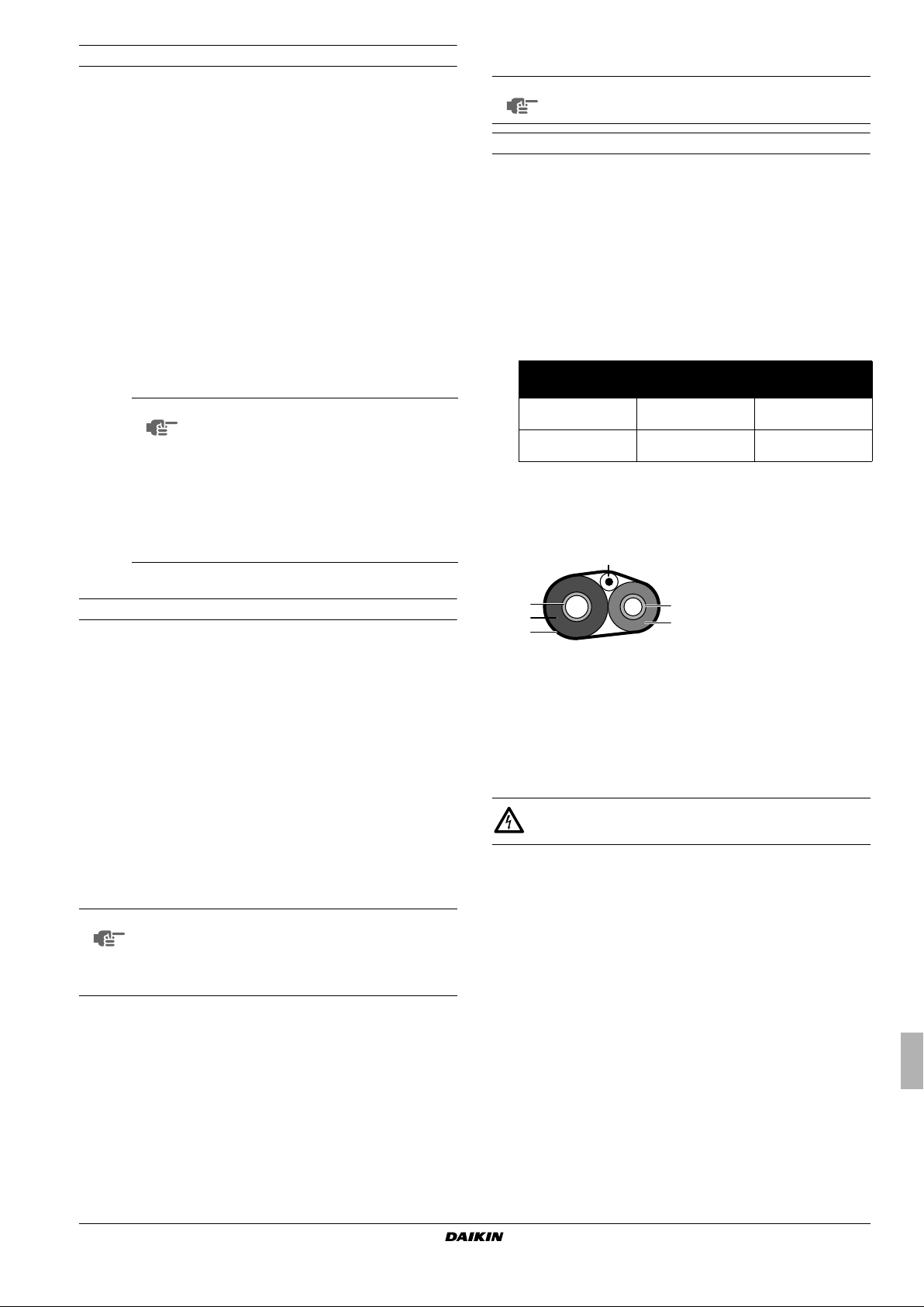
59
(15)77(25)
122
(50)
5
(–15)
77
(25)
°F DB
(°C DB)
°F
(°C)
A
B
50
(10)
86
(30)
Equipment which is delivered with the unit and which needs to be
installed according to instructions in the documentation.
Optional equipment:
Equipment which can optionally be combined to the products as per
the subject of this manual.
Field supply:
Equipment which needs to be installed according to instructions in
this manual, but which are not supplied by Daikin.
2. I
NTRODUCTION
2.4. Operation range
In cooling mode
°F DB
(°C DB)
A
109
(43)
This manual describes the procedures for handling, installing and
connecting all ERLQ018~030BAVJU units. This manual has been
prepared to ensure adequate maintenance of the unit, and it will
provide help if problems occur.
NOTE
The installation of the indoor unit(s) is described in the
indoor unit installation manual.
2.1. General information
The outdoor units are intended for household heating and cooling.
2.2. Model identification
E R L Q 030 BA VJU
Voltage supply
Series
Capacity Class
Refrigerant R410A
Low ambient type
Outdoor unit
Model produced in Europe
2.3. Combination and options
The outdoor units should be combined with one of the following
indoor units:
■
EKHBH030*VJU: heating only
■
EKHBX030*VJU: heating and cooling
Possible options are:
■
EKHWS050+080*VJU: domestic hot water tank
■
EKSOL**VJU: solar kit
50
(10)
41
(5)
A
Outdoor temperature
B
Leaving evaporator water temperature
Pull down area
72
(22)
In heating mode
A
Outdoor temperature
B
Leaving condensor water temperature
Only backup heater operation (no outdoor unit operation)
In domestic water heating mode
122
(50)
B
°F
(°C)
ERLQ018~030BAVJU
Outdoor unit for air to water heat pump
4PW62590-1 – 07.2010
°F DB
(°C DB)
95
(35)
77
(25)
41
(5)
(–15)
A
B
A
5
113
122
77
(25)
Outdoor temperature
Domestic hot water tank water temperature
Only booster heater operation
(45)
(50)
131
(55)
B
176
°F
(80)
(°C)
Installation manual
2
3. A
CCESSORIES
5. O
VERVIEW OF UNIT
Accessories supplied with this unit:
Installation manual 1x
4. G
ENERAL SAFETY PRECAUTIONS
All activities described in this manual shall be carried out by an
installer.
Be sure to wear adequate personal protection equipment (protection
gloves, safety glasses, …) when performing installation, maintenance
or service to the unit.
If not sure of installation procedures or operation of the unit, always
contact your local dealer for advice and information.
Improper installation or attachment of equipment or accessories
could result in electric shock, short-circuit, leaks, fire or other damage
to the equipment. Be sure only to use accessories and optional
equipment made by Daikin which are specially designed for use with
the products as of subject in this manual and have them installed by
an installer.
DANGER: ELECTRICAL SHOCK
Switch off all power supply before removing the switchbox
service panel or before making any connections or
touching electrical parts.
To avoid electric shock, be sure to disconnect the power
supply 1 minute or more before servicing the electrical
parts. Even after 1 minute, always measure the voltage at
the terminals of main circuit capacitors or electrical parts
and, before touching, be sure that those voltages are
50 V DC or less.
When service panels are removed, live parts can easily be
touched by accident. Never leave the unit unattended
during installation or servicing when the service panel is
removed.
DANGER: DO NOT TOUCH PIPING AND INTERNAL
PA RT S
Do not touch the refrigerant piping, water piping or internal
parts during and immediately after operation. The piping
and internal parts may be hot or cold depending on the
working condition of the unit.
Your hand may suffer burns or frostbite if you touch the
piping or internal parts. To avoid injury, give the piping and
internal parts time to return to normal temperature or, if
you must touch them, be sure to wear protective gloves.
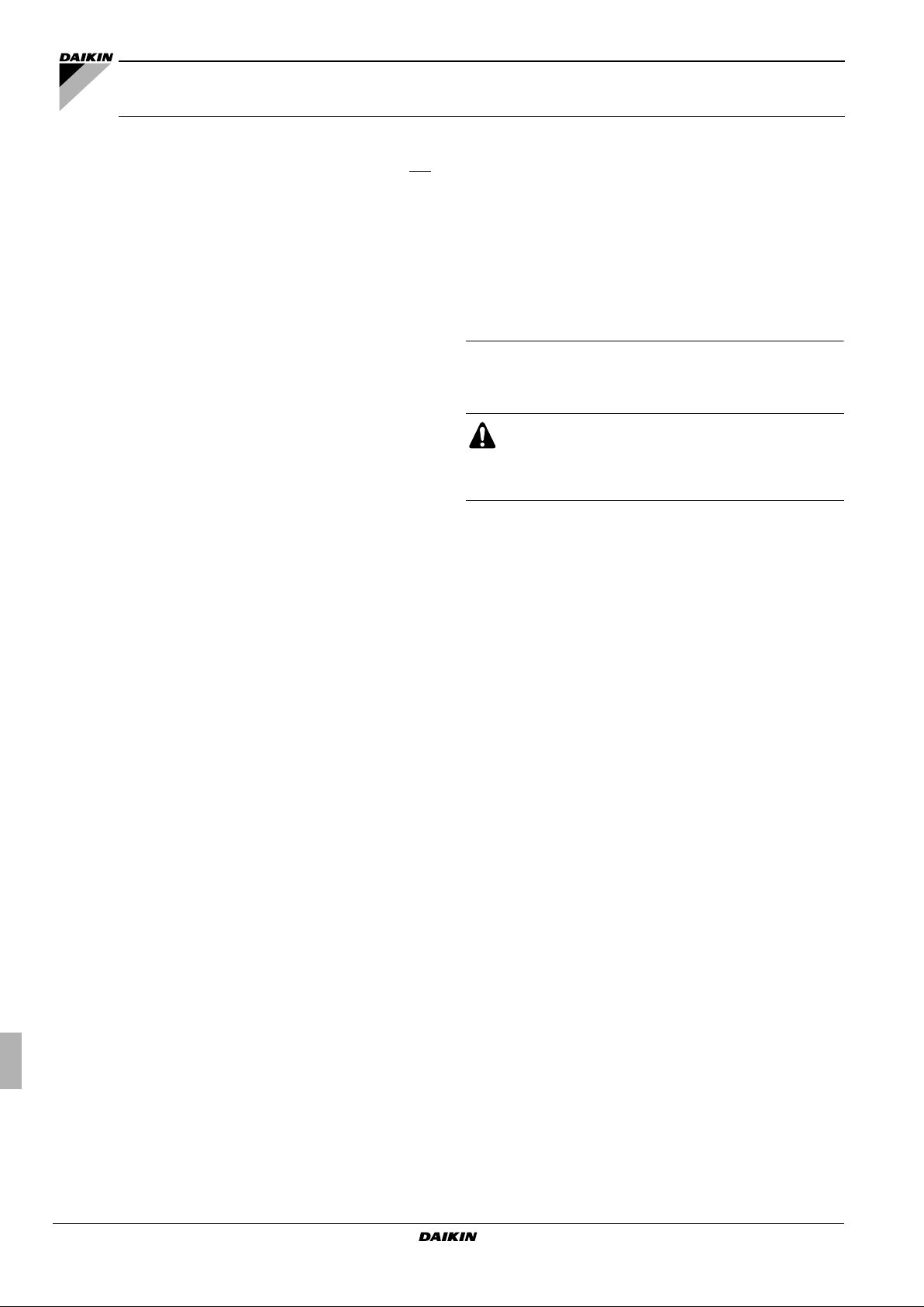
5.1. Opening the unit
1
Cable cover
2
Service panel
3
Stop valve cover
DANGER: ELECTRICAL SHOCK
See "4. General safety precautions" on page 3.
DANGER: DO NOT TOUCH PIPING AND INTERNAL
PA RT S
See "4. General safety precautions" on page 3.
5.2. Main components
Unit
1
23
2 31
6x
Installation manual
3
1
Heat exchanger
2
Fan
3
Electrical component box
4
4-way valve
5
Expansion valve
6
Accumulator
4
5
6
7
8
9
Outdoor unit for air to water heat pump
ERLQ018~030BAVJU
4PW62590-1 – 07.2010
7
4
3
1
2
6
5
7
Compressor
8
Liquid stop valve
9
Gas stop valve
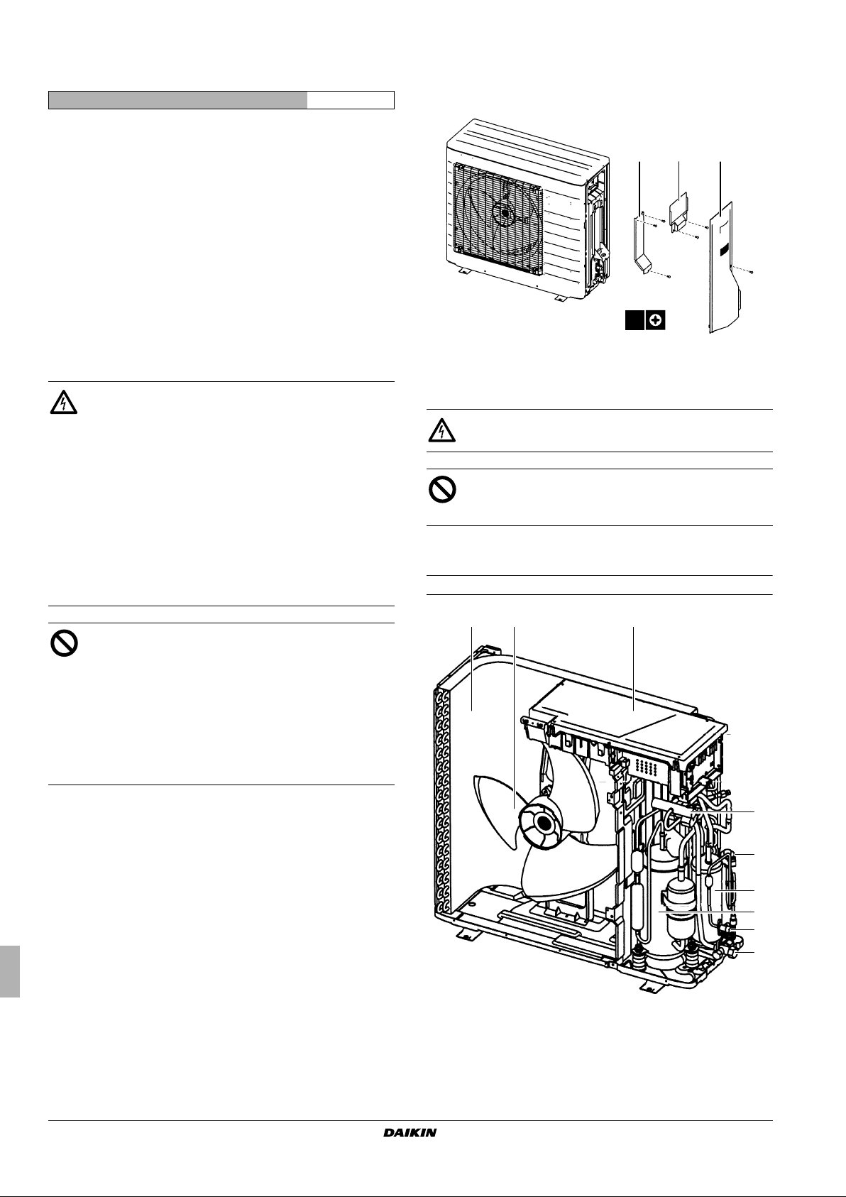
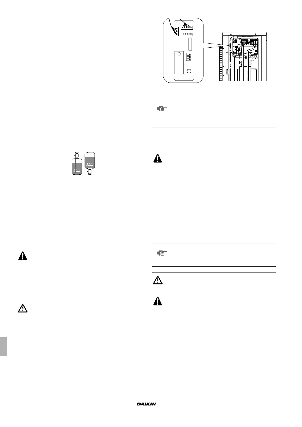
Switchbox
12 3
1
Reactor
2
Inverter PCB
3
Service monitor PCB
4
Power supply terminal
5
Communication terminal
6
Communication bottom plate heater
5.3. Functional diagram
6. P
RECAUTIONS ON INSTALLATION LOCATION
WARNING
Be sure to provide for adequate measures in order to
prevent that the unit be used as a shelter by small animals.
Small animals making contact with electrical parts can
cause malfunctions, smoke or fire. Please instruct the
customer to keep the area around the unit clean and clear.
6.1. General precautions
Select an installation site that meets the following requirements:
■
There must be sufficient space for carrying the unit into and out
of the site.
■
4
5
6
6
The foundation must be strong enough to support the weight of
the unit. The floor is flat to prevent vibrations and noise
generation and to have sufficient stability.
■
The space around the unit is adequate for maintenance and
servicing.
■
The space around the unit allows for sufficient air circulation.
■
There is no danger of fire due to leakage of inflammable gas.
■
The equipment is not intended for use in a potentially explosive
atmosphere.
■
Select the location of the unit in such a way that the sound and
discharged cold/hot air generated by the unit does not disturb
anyone, and the location is selected according the applicable
legislation.
■
All piping lengths and distances have been taken into
consideration.
■
Ta ke care that in the event of a water leak, water cannot cause
any damage to the installation space and surroundings.
NOTE
Units cannot be installed hanging from ceiling or
stacked.
■
Do not install the unit in places such as the following:
■
Where there is mist of mineral oil, oil spray or vapour for
example a kitchen.
Plastic parts may deteriorate, and cause them to fall out or
water to leak.
■
Where corrosive gas, such as sulphurous acid gas, is
produced.
Corrosion of copper pipes or soldered parts may cause the
refrigerant to leak.
■
Where there is machinery which emits electromagnetic
waves.
Electromagnetic waves may disturb the control system, and
cause malfunction of the equipment.
■
Where flammable gases may leak, where carbon fiber or
ignitable dust is suspended in the air or where volatile
flammables, such as thinner or gasoline, are handled.
1
2
3
4
5
6
7
Heat exchanger
4-way valve
Compressor
Accumulator
Expansion valve
Liquid stop valve
Gas stop valve
Such gases may cause a fire.
■
Where the air contains high levels of salt such as that near
the ocean.
■
Where voltage fluctuates a lot, such as that in factories.
■
In vehicles or vessels.
■
Where acidic or alkaline vapour is present.
ERLQ018~030BAVJU
Outdoor unit for air to water heat pump
4PW62590-1 – 07.2010
Installation manual
4
6.2. Weather dependent precautions
■
Select a place where the rain can be avoided as much as
possible.
■
Since drain flows out of the outdoor unit, do not place anything
under the unit which must be kept away from moisture.
■
Ensure that water cannot cause any damage to the location by
adding water drains to the foundation and prevent water traps in
the construction.
1
If the water drainage of the unit is not easy, please build up the
unit on a foundation of concrete blocks, etc. (the height of the
foundation should be maximum 5.9 inch (150 mm)).
2
If you install the unit on a frame, please install a waterproof plate
within 5.9 inch (150 mm) of the underside of the unit in order to
prevent the invasion of water from the lower direction.
3
If you install the unit on a building frame,
please install a waterproof plate within
5.9 inch (150 mm) of the underside of the
unit in order to avoid the drainwater
dripping.
■
When installing the unit in a place exposed to strong wind, pay
special attention to the following:
1
Strong winds of 16.40 ft/sec (5 m/sec) or more blowing against
the unit's air outlet causes short circuit (suction of discharge air),
and this may have the following consequences:
- Deterioration of the operational capacity.
-Frequent frost acceleration in heating operation.
- Disruption of operation due to rise of high pressure.
- When a strong wind blows continuously on the face of the
unit, the fan can start rotating very fast until it breaks.
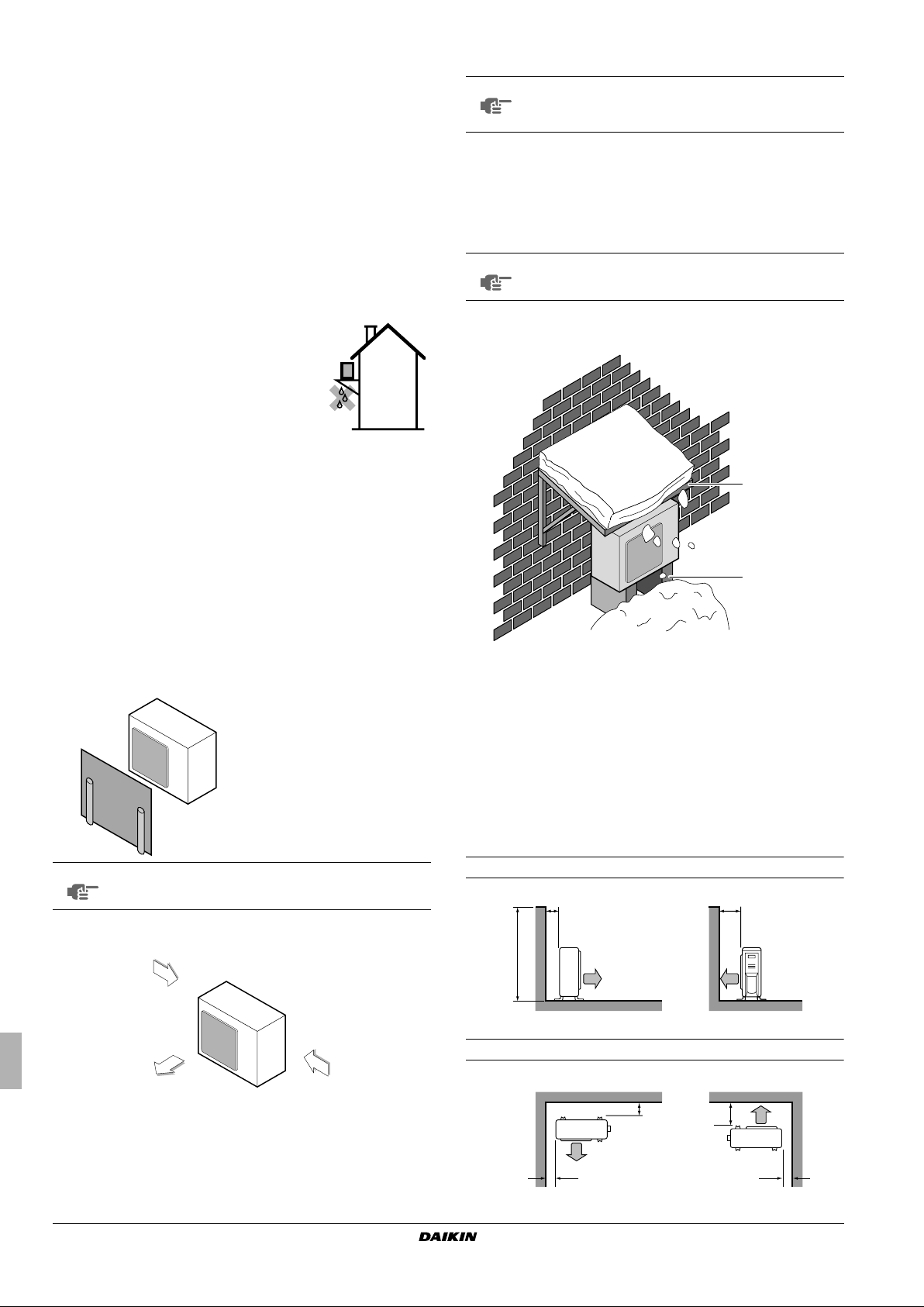
6.3. Selecting a location in cold climates
NOTE
■
■
■
NOTE
■
When operating the unit in a low outdoor ambient
temperature, be sure to follow the instructions
described below.
To prevent exposure to wind, install the unit with its suction side
facing the wall.
Never install the unit at a site where the suction side may be
exposed directly to wind.
To prevent exposure to wind, install a baffle plate on the air
discharge side of the outdoor unit.
Mind the restrictions: refer to "6.4. Installing near a wall
or obstacle" on page 5
In heavy snowfall areas it is very important to select an
installation site where the snow will not affect the unit:
1
2
2
Refer to the figure below for installation of this unit in a place
where the wind direction can be foreseen.
■
Install a baffle plate on the air discharge side of the outdoor unit:
1
1 Baffle plate
NOTE
Mind the restrictions: refer to "6.4. Installing near a wall
or obstacle" on page 5
■
Set the outlet side at a right angle to the direction of the wind.
Strong wind
Blown air Strong wind
1
Construct a large canopy.
2
Construct a pedestal.
Install the unit high enough off the ground to prevent burying
in snow.
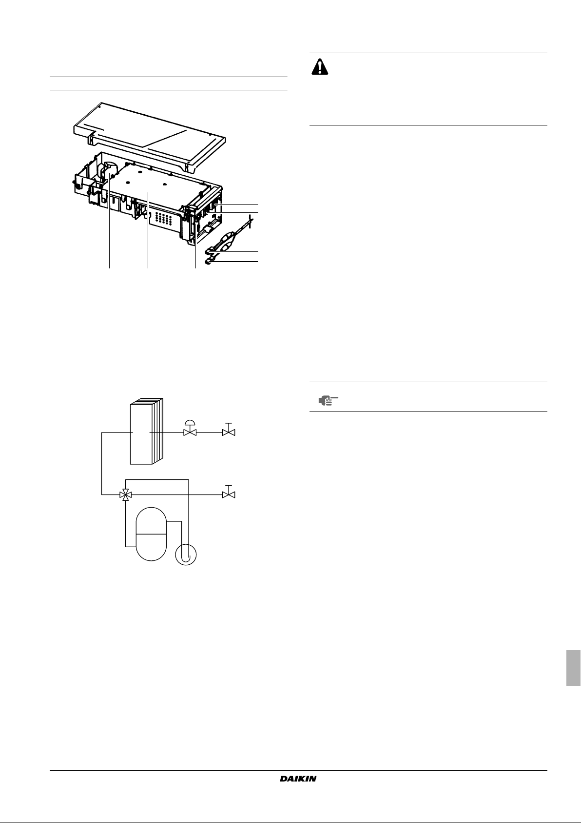
6.4. Installing near a wall or obstacle
■
Where a wall or other obstacle is in the path of the outdoor unit
air intake or exhaust airflow, follow the installation guidelines
below.
■
For any of the installation patterns below, the wall height on the
exhaust side should be 47.24 inch (1200 mm) or less.
Wall facing one side
>3.94 (100) >13.78 (350)
≤47.24 (1200)
inch (mm) inch (mm)
Walls facing two sides
inch (mm) inch (mm)
Installation manual
5
>3.94 (100)
>1.97 (50)
>13.78 (350)
>1.97 (50)
Outdoor unit for air to water heat pump
ERLQ018~030BAVJU
4PW62590-1 – 07.2010
Walls facing three sides
12.99 (330)
22.83 (580)
4.72 (120)
3
1
2
6
4
5
unit: inch (mm)
7.4. Installation instructions
inch (mm)
>3.94 (100)
>1.97 (50)
>13.78 (350)
6.5. Additional precautions
It is recommended to install the equipment and electric wires keeping
proper distances away from stereo equipment, personal computers,
etc... In extreme circumstances you shall keep distances of 9.84 ft
(3 m) or more and use conduit tubes for power and transmission
lines.
■
Do not install the unit in places often used as work place.
■
In case of construction works (e.g. grinding works) where a lot of
dust is created, the unit must be covered.
■
Do not place any objects or equipment on top of the unit (top
plate).
■
Do not climb, sit or stand on top of the unit,
■
Be sure that sufficient precautions are taken, in accordance with
the applicable legislation, in case of refrigerant leakage.
7. I
NSTALLATION OF THE UNIT
Mounting the outdoor unit
When installing the outdoor unit, please refer to "6. Precautions on
installation location" on page 4 to select an appropriate location.
1 Check the strength and level of the installation ground so that
the unit will not cause any operating vibration or noise after
installation.
2 Prepare 4 sets of 0.31 inch [close to 5/16 inch] (M8) or 0.39 inch
[close to 3/8 inch] (M10) foundation bolts, nuts and washers
each (field supply).
3 Fix the unit securely by means of the foundation bolts in
accordance with the figure below.
It is best to screw in the foundation bolts until their length
remains 0.79 inch (20 mm) above the foundation surface.
(20 mm)
0.79 inch
Outdoor installation drawing
7.1. Unpacking the unit
Check if all unit accessories are enclosed.
WARNING
Tear apart and throw away plastic packaging bags so that
children will not play with them. Children playing with
plastic bags face danger of death by suffocation.
7.2. Inspection
At delivery, the unit must be checked and any damage must be
reported immediately to the carrier's claims agent.
7.3. Handling the unit
As shown in the figure below, bring the unit slowly by grabbing the left
and right grips.
Do not hold the suction inlet in the side of the casing, otherwise the
casing could be deformed.
CAUTION
To avoid injury, do not touch the air inlet or aluminium fins
of the unit.
1 Wrap the insulation pipe with finishing tape from bottom to top.
2 Stop valve cover
3 9.84 inch (250 mm) from wall. Allow space for piping and electrical
servicing.
4 If there is danger of the unit falling or overturning, fix the unit with
foundation bolts, or with wire or other means.
5 Distance from the outer side of the stop valve cover
6 If the location does not have good drainage, place the unit on
block bases. Adjust foot height until the unit is levelled. Failure to
do so may result in water leakage or accumulation.
ERLQ018~030BAVJU
Outdoor unit for air to water heat pump
4PW62590-1 – 07.2010
Installation manual
6
Drain work
9. PRECAUTIONS ON REFRIGERANT PIPING
Refer to "6.2. Weather dependent precautions" on page 5.
■ If drain work from the outdoor unit causes trouble (for example, if
the drain water may splash on people) provide a waterproof
plate (field supply) within 5.9 inch (150 mm) of the underside of
the unit.
■ Make sure the drain works properly.
NOTE
If drain holes of the outdoor
unit are covered by a
mounting base or by floor
surface, raise the unit in
order to provide a free
space of more than
≥3.94 inch
3.94 inch (100 mm) under
(≥100 mm)
the outdoor unit.
8. REFRIGERANT PIPE SIZE AND ALLOWABLE
PIPE LENGTH
8.1. Refrigerant piping material
NOTE
Piping and other pressure containing parts shall
comply with the applicable legislation and shall be
suitable for refrigerant. Use phosphoric acid
deoxidised seamless copper for refrigerant.
CAUTION
R410A, as well as other refrigerants, should always be
recovered and never be released directly into the
environment.
■ Do not allow anything other than the designated refrigerant to
get mixed into the freezing cycle, such as air, etc. If any
refrigerant gas leaks while working on the unit, ventilate the
room thoroughly right away.
■ Use R410A only when adding refrigerant
- Installation tools:
Make sure to use installation tools (gauge manifold charge
hose, etc.) that are exclusively used for R410A installations
to withstand the pressure and to prevent foreign materials
(e.g. mineral oils and moisture) from mixing into the system.
-Vacuum pump:
Use a 2-stage vacuum pump with a non-return valve.
Make sure the pump oil does not flow oppositely into the
system while the pump is not working.
Use a vacuum pump which can evacuate to –14.6 psi
[–100.7 kPa (5 Torr, –755 mm Hg)].
■ In order to prevent dirt, liquid or dust from entering the piping,
cure the piping with a pinch or taping.
8.2. Piping material selection
CAUTION
Never use piping which has been used for previous
installations. Only use parts which are delivered with the
unit.
■ Foreign materials inside pipes (including oils for fabrication)
must be ≤0.014 grain/ft (30 mg/10 m).
■ Temper grade: use piping with temper grade in function of the
pipe diameter as listed in table below.
■ The pipe thickness of the refrigerant piping shall comply with the
applicable legislation. The minimal pipe thickness for R410A
piping must be in accordance with the table below.
Temper grade of
Pipe size
1/4 inch (Ø6.4 mm) O 0.031 inch (0.8 mm)
5/8 inch (Ø15.9 mm) O 0.039 inch (1.0 mm)
O = Annealed
piping material
Minimal thickness
8.3. Refrigerant piping specifications
Refrigerant piping specifications
Maximum allowable piping length
between outdoor unit and indoor unit
Minimum required piping length
between outdoor unit and indoor unit
Maximum allowable height difference
between outdoor unit and indoor unit
Additional refrigerant required for
refrigerant pipe exceeding 32.8 ft (10 m)
in length
Gas pipe - outer diameter 5/8 inch (15.9 mm)
Liquid pipe - outer diameter 1/4 inch (6.4 mm)
98.4 ft (30 m)
9.8 ft (3 m)
65.6 ft (20 m)
0.013 lbs/ft (20 g/m)
Installation period Protection method
More than a month Pinch the pipe
Less than a month
Regardless of the period
Pinch or tape the pipe
- Great caution is needed when passing copper tubes through
walls.
9.1. Guidelines for brazing
■ Make sure to blow through with nitrogen when brazing.
Blowing through with nitrogen prevents the creation of large
quantities of oxidized film on the inside of the piping. An oxidized
film adversely affects valves and compressors in the
refrigerating system and prevents proper operation.
■ The nitrogen pressure should be set to 2.9 psi (0.02 MPa) (i.e.,
just enough so it can be felt on the skin) with a pressurereducing valve.
12 345
6
1 Refrigerant piping
2 Part to be brazed
3 Taping
4 Hands valve
5 Pressure-reducing valve
6 Nitrogen
■ Do not use anti-oxidants when brazing the pipe joints.
Residue can clog pipes and break equipment.
6
Installation manual
7
Outdoor unit for air to water heat pump
ERLQ018~030BAVJU
4PW62590-1 – 07.2010
■ Do not use flux when brazing copper-to-copper refrigerant
1 Service port and service port cover
2 Stop valve
3 Field piping connection
4 Stop valve cover
piping. Use phosphor copper brazing filler alloy (BCuP) which
does not require flux.
■ Flux has an extremely harmful influence on refrigerant piping
systems. For instance, if chlorine based flux is used, it will cause
pipe corrosion or, in particular, if the flux contains fluorine, it will
deteriorate the refrigerant oil.
9.3. Guidelines for handling the stop valve
Cautions for handling the stop valve
■ Make sure to keep both stop valves open during operation.
■ The figure below shows the name of each part required in
handling the stop valve.
9.2. Guidelines for flare connection
CAUTION
■ Do not use mineral oil on flared part.
Mineral oil getting into the system would reduce the
lifetime of the units.
■ Incomplete flaring may cause refrigerant gas leakage.
■ Flares should not be re-used. New ones should be made in
order to prevent leaks.
■ Use a pipe cutter and annealed flare tool suitable for the
refrigerant used.
■ Only use the annealed flare nuts included with the unit. Using
different flare nuts may cause the refrigerant to leak.
■ Please refer to the table for flaring dimensions and tightening
torques (too much tightening will result in splitting the flare).
Tightening
Piping size
1/4 inch
(Ø6.4 mm)
5/8 inch
(Ø15.9 mm)
torque
11.06~12.54 lbs•ft
(15~17 N•m)
46.47~55.32 lbs•ft
(63~75 N•m)
■ When connecting the flare nut, coat the flare inner surface with
ether oil or with ester oil and initially tighten 3 or 4 turns by hand
before tightening firmly.
Flare
dimensions A
0.34~0.36 inch
(8.7~9.1 mm)
0.76~0.78 inch
(19.3~19.7 mm)
Flare shape
(mm)
±2
90
45
±2
A
R=0.02~0.04 inch
(=0.4~0.8 mm)
1
2
3
4
■ The stop valve is factory closed.
■ Do not apply excessive force to the stop valve. Doing so may
break the valve body.
Since the stop valve mounting plate may be deformed if only a
torque wrench is used to loosen or tighten the flare nut, always
make sure to secure the stop valve with a spanner, then loosen
or tighten the flare nut with a torque wrench.
Do not place the spanner on the stop valve cover, as this could
cause a refrigerant leak.
1
2
1 Spanner
2 Torque wrench
■ The operating pressure at the refrigerant side can be low,
sufficiently seal the flare nut in the stop valve on the gas line with
silicon sealant to prevent freezing.
■ After all piping has been connected, use nitrogen to perform a
gas leak check.
■ When loosening a flare nut, always use two wrenches together.
When connecting the piping, always use a spanner and torque
wrench together to tighten the flare nut to prevent flare nut
cracking and leaks.
1
4
3
1 Torque wrench
2 Spanner
3 Piping union
2
4 Flare nut
■ After the work is finished, make sure to check that there is no
gas leak.
Silicon sealant
(Make sure there is no gap)
How to use the stop valve
■ Opening the stop valve
1. Remove the stop valve cover.
2. Insert a hexagon wrench (0.15 inch [close to 5/32 inch] (4 mm))
into the stop valve and turn the stop valve counter clockwise.
3. When the stop valve cannot be turned any further, stop turning.
The valve is now open.
■ Closing the stop valve
1. Remove the stop valve cover.
2. Insert a hexagon wrench (0.15 inch [close to 5/32 inch] (4 mm))
into the stop valve and turn the stop valve clockwise.
3. When the stop valve cannot be turned any further, stop turning.
The valve is now closed.
Closing direction
Liquid side Gas side
ERLQ018~030BAVJU
Outdoor unit for air to water heat pump
4PW62590-1 – 07.2010
Installation manual
8
Cautions for handling the stop valve cover
■ The stop valve cover is sealed where indicated by the arrow.
Ta ke care not to damage it.
■ After handling the stop valve, make
sure to tighten the stop valve cover
securely. For the tightening torque,
refer to the table below.
■ Check for refrigerant leaks after
tightening the stop valve cover.
Cautions for handling the service port
■ Always use a charge hose equipped with a valve depressor pin,
since the service port is a Schrader type valve.
■ After handling the service port, make sure to tighten the service
port cover securely. For the tightening torque, refer to the table
below.
■ Check for refrigerant leaks after tightening the service port
cover.
Tightening torques
Item Tightening torque
Stop valve cover, liquid side 15.93~29.21 lbs•ft (21.6~27.4 N•m)
Stop valve cover, gas side 32.53~39.75 lbs•ft (44.1~53.9 N•m)
Service port cover 7.97~10.84 lbs•ft (10.8~14.7 N•m)
10. PIPING CONNECTION WORK
10.1. Preventing foreign objects from entering
■ Plug the pipe through-holes with putty or insulating material
(field supply) to stop up all gaps, as shown in the figure.
1 Putty or insulating material
(field supply)
1
■ Insects or small animals entering the outdoor unit may cause a
short circuit in the electrical box.
10.2. Leak test and vacuum drying
DANGER: ELECTRICAL SHOCK
See "4. General safety precautions" on page 3.
When all piping work is complete, it is necessary to:
■ check for any leakages in the refrigerant piping and
■ to perform vacuum drying to remove all moisture in the
refrigerant piping.
If there is a possibility of moisture being present in the refrigerant
piping (for example, rainwater may have entered the piping), first
carry out the vacuum drying procedure below until all moisture has
been removed.
WARNING
During installation, attach the refrigerant piping securely
before running the compressor.
If the compressor is not attached and the stop valve is
open during pump-down, air will be sucked in when the
compressor is running, causing abnormal pressure in the
freezer cycle which will lead to breakage and even to
injury.
CAUTION
Do never install a drier to this R410A unit in order to
guarantee its lifetime. The drying material may dissolve
and damage the system.
NOTE
1. Installation shall be done by an installer, the
choice of materials and installation shall comply
with the applicable legislation.
2. To persons in charge of piping work:
■ Be sure to open the stop valve after piping
installing and vacuming is complete. Running
the system with the valve closed may break
the compressor.
■ When the refrigerant system is to be opened,
refrigerant must be treated according the
applicable legislation.
■ Ensure that the field piping and connections
are not subjected to stress.
General guidelines
■ All piping inside the unit has been factory tested for leaks.
■ Use a 2-stage vacuum pump with a non-return valve which can
evacuate to a gauge pressure of –14.6 psi [–100.7 kPa
(5 Torr absolute, –755 mm Hg)].
NOTE
■ Do not purge the air with refrigerants. Use a
vacuum pump to evacuate the installation. No
additional refrigerant is provided for air purging.
■ Make sure that the gas stop valve and liquid stop
valve are firmly closed before performing the leak
test or vacuum drying.
Setup
1
48
2
3
5
6
789
1 Pressure meter
2 Gauge manifold
3 Low-pressure valve (Lo)
4 High-pressure valve (Hi)
5 Charging hoses
10
6 Vacuum pump
7 Service port
8 Stop valve cover
9 Gas stop valve
10 Liquid stop valve
Installation manual
9
Outdoor unit for air to water heat pump
ERLQ018~030BAVJU
4PW62590-1 – 07.2010
Leak test
1
2
3
4
6
5
1 Gas pipe
10.3. Pipe insulation
1 Vacuum leak test
1.1 Fully open the gauge manifold’s low-pressure valve (Lo)
and completely close its high-pressure valve (Hi). The highpressure subsequently requires no operation.
1.2 Evacuate the system from the gas piping to –14.6 psi
[–100.7 kPa (5 Torr, –755 mm Hg)].
1.3 Once reached, close the gauge manifold’s low-pressure
valve (Lo), turn off the vacuum pump and check that the
pressure does not rise for about 4-5 minutes.
1.4 Should the pressure rise, the system may either contain
moisture (see vacuum drying below) or have leaks.
2 Pressure leak test
2.1 Break the vacuum by pressurizing with nitrogen gas to a
minimum gauge pressure of 29 psi [0.2 MPa (2 bar)].
Never set the gauge pressure higher than the maximum
operation pressure of the unit, i.e. 605 psi [4.17 MPa
(41.7 bar)].
2.2 Test for leaks by applying a bubble test solution to all piping
connections.
NOTE
Make sure to use a recommended bubble
test solution from your wholesaler.
Do not use soap water, which may cause
cracking of flare nuts (soap water may
contain salt, which absorbs moisture that will
freeze when the piping gets cold), and/or
lead to corrosion of flared joints (soap water
may contain ammonia which causes a
corrosive effect between the brass flare nut
and the copper flare).
2.3 Discharge all nitrogen gas.
Vacuum drying
To remove all moisture from the system, proceed as follows:
1 Evacuate the system for at least 2 hours to a target vacuum of
–14.6 psi [–100.7 kPa (5 Torr, –755 mm Hg)].
2 Check that, with the vacuum pump turned off, the target vacuum
is maintained for at least 1 hour.
3 Should you fail to reach the target vacuum within 2 hours or
maintain the vacuum for 1 hour, the system may contain too
much moisture.
4 In that case, break the vacuum by pressurizing with nitrogen gas
to a gauge pressure of 7.25 psi [0.05 MPa (0.5 bar)] and repeat
steps 1 to 3 until all moisture has been removed.
5 The stop valves can now be opened, and/or additional
refrigerant can be charged (see "11.1. Additional refrigerant
charging" on page 11).
NOTE
After opening the stop valve, it is possible that the
pressure in the refrigerant piping does not rise. This
might be caused by e.g. the closed state of the
expansion valve in the outdoor unit circuit, but does not
present any problem for correct operation of the unit.
NOTE
Any exposed piping may cause condensation or bruns
if touched.
Selection of heat insulation materials
When using commercial copper pipes and fittings, observe the
following:
■ Insulation material: polyethylene foam
2
Heat transfer rate: 0.285~0.361 BTU.inch/h.ft
.°F (0.041~0.052
W/m•K)
Refrigerant gas pipe's surface temperature reaches 230°F
(110°C) max.
Choose heat insulation materials that will withstand this
temperature.
■ Be sure to insulate both the gas and liquid piping and to provide
insulation dimensions as below.
Pipe insulation
Connection pipe Inner diameter Thickness
1/4 inch
(Ø6.4 mm)
5/8 inch
(Ø15.9 mm)
0.31~0.39 inch
(8~10 mm)
0.63~0.79 inch
(16~20 mm)
≥0.39 inch
(10 mm)
≥0.51 inch
(13 mm)
■ If the temperature is higher than 86°F (30°C) and the humidity is
higher than RH 80%, then the thickness of the sealing materials
should be at least 0.79 inch (20 mm) in order to avoid
condensation on the surface of the sealing.
2 Conduit including
interunit wiring
3 Liquid pipe
4 Liquid pipe insulation
5 Finishing tape
6 Gas pipe insulation
■ Use separate thermal insulation pipes for gas and liquid
refrigerant pipes.
11. CHARGING REFRIGERANT
DANGER: ELECTRICAL SHOCK
See "4. General safety precautions" on page 3.
■ Refrigerant cannot be charged until field wiring has been
completed.
■ Refrigerant may only be charged after performing the leak test
and the vacuum drying.
■ When charging a system, care shall be taken that its maximum
permissible charge is never exceeded, in view of the danger of
liquid hammer.
■ Charging with an unsuitable substance may cause explosions
and accidents, so always ensure that the appropriate refrigerant
R410A is charged.
■ Refrigerant containers shall be opened slowly.
■ Always use protective gloves and protect your eyes when
charging refrigerant.
■ When the refrigerant system is to be opened, refrigerant must
be treated according to the applicable legislation.
ERLQ018~030BAVJU
Outdoor unit for air to water heat pump
4PW62590-1 – 07.2010
Installation manual
10
11.1. Additional refrigerant charging
■ This outdoor unit is factory charged with refrigerant and
depending on pipe sizes and pipe lengths some systems require
additional charging of refrigerant. See "11.3. Charging amount"
on page 11.
■ In case re-charge is required, refer to the nameplate of the unit.
It states the type of refrigerant and necessary amount.
11.2. Precautions when adding R410A
■ The refrigerant requires strict cautions for keeping the system
clean, dry and tight.
- Clean and dry
Foreign materials (including mineral oils or moisture) should
be prevented from getting mixed into the system.
- Tight
Read "9. Precautions on refrigerant piping" on page 7
carefully and follow these procedures correctly.
■ Make sure to charge the refrigerant in liquid state to the liquid
pipe. Since R410A is a mixed refrigerant, its composition
changes if charged in its gaseous state and normal system
operation would then no longer be assured.
■ Before charging, check whether the refrigerant cylinder has a
syphon attached or not and position the cylinder accordingly.
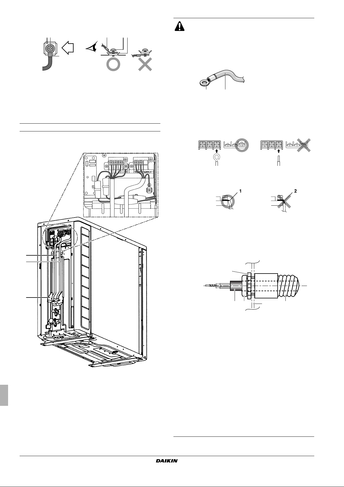
Filling using a cylinder
with a siphon attached
Charge the liquid refrigerant
with the cylinder in upright
position.
Filling using a cylinder
without a siphon attached
Charge the liquid refrigerant
with the cylinder in up-sidedown position.
11.3. Charging amount
If the total length of the piping exceeds 32.8 ft (10 m), additionally
charge with 0.013 lbs/ft (20 g/m) for each additional foot (meter) of
piping.
12. PUMP DOWN OPERATION
In order to protect the environment, be sure to pump down when
relocating or disposing of the unit. The pump down operation will
extract all regrigerant from the piping into the outdoor unit.
WARNING
During pump down operation, stop the compressor before
removing the refrigerant piping.
If the compressor is still running and the stop valve is open
during pump-down, air will be sucked in when the
refrigerant piping is removed, causing abnormal pressure
in the freezer cycle which will lead to breakage and even to
injury.
DANGER: ELECTRICAL SHOCK
See "4. General safety precautions" on page 3.
12.1. Procedure
1 Tu rn on the main power supply.
2 Make sure the liquid stop valve and the gas stop valve are open
(see "How to use the stop valve" on page 8).
3 Press the forced operation switch SW1 to begin forced cooling.
4 After 5-10 minutes (after only 1 or 2 minutes in case of very low
ambient temperatures (<14°F (–10°C)), close the liquid stop
valve.
5 After 2-3 minutes, close the gas stop valve and press the forced
operation switch SW1 again to stop forced cooling.
S102
S2
LED-A
ABCD
SW4
ON
SW1
1 Forced operation switch SW1
NOTE
Ta ke care that while running forced cooling operation
1
the water temperature remains higher than 41°F (5°C)
(see temperature read out of the indoor unit). You can
achieve this, for example, by activating all fans of the
fan coil units.
13. ELECTRIC WIRING WORK
ATTENTION
■ All field wiring and components must be installed by
an installer and must comply with the applicable
legislation.
■ The equipment described in this manual may cause
electronic noise generated from radio-frequency
energy. The equipment complies to specifications that
are designed to provide reasonable protection against
such interference. However, there is no guarantee that
interference will not occur in a particular installation.
It is therefore recommended to install the equipment and
electric wires keeping proper distances away from stereo
equipment, personal computers, etc....
In extreme circumstances you shall keep distances of
9.84 ft (3 m) or more.
NOTE
To persons in charge of electrical wiring work:
Do not operate the unit until the refrigerant piping is
complete. Running the unit before the piping is ready
will break the compressor.
DANGER: ELECTRICAL SHOCK
See "4. General safety precautions" on page 3.
WARNING
■ A main switch or other means for disconnection, having a
contact separation in all poles, must be incorporated in
the fixed wiring in accordance with the applicable
legislation.
■ Use only copper wires.
■ All field wiring must be carried out in accordance with the
wiring diagram supplied with the unit and the instructions
given below.
■ Never squeeze bundled cables and be sure that it does
not come in contact with the non-insulated piping and
sharp edges. Be sure no external pressure is applied to
the terminal connections.
■ Be sure to establish a ground. Do not ground the unit to a
utility pipe, surge absorber, or telephone ground.
Incomplete ground may cause electrical shock.
Installation manual
11
Outdoor unit for air to water heat pump
ERLQ018~030BAVJU
4PW62590-1 – 07.2010

■ Be sure to install a ground fault circuit interrupter in
accordance with the applicable legislation. Failure to do
so may cause electric shock or fire.
■ Be sure to use a dedicated power circuit, never use a
power supply shared by another appliance.
■ When installing the ground fault circuit interrupter be sure
that it is compatible with the inverter (resistant to high
frequency electric noise) to avoid unnecessary opening
of the ground fault circuit interrupter.
■ The ground fault circuit interrupter must be a high speed
type breaker of 30 mA (<0.1 seconds).
■ As this unit is equipped with an inverter, installing a
phase advancing capacitor not only will deteriorate
power factor improvement effect, but also may cause a
capacitor abnormal heating accident due to highfrequency waves. Therefore, never install a phase
advancing capacitor.
■ Be sure to install the required fuses or circuit breakers.
■ Use a cable long enough to cover the entire distance. Do
not use an extension cord.
CAUTION
For use of units in applications with temperature alarm
settings its advised to foresee a delay of 10 minutes for
signalling the alarm in case the alarm temperature is
exceeded. The unit may stop for several minutes during
normal operation for "defrosting he unit", or when in
"thermosta-stop" operation.
13.1. Switch box component list
AC1,AC2.......................Connector
E1,E2............................Connector
E1H...............................Bottomplate heater
FU1...............................Fuse, T 30 A/250 V
FU2,FU3.......................Fuse, T 3.15A/250 V
FU4,FU5.......................Fuse, F 1 A/250 V
HR1,HR2 ......................Connector
L1,L2.............................Live
L1R...............................Reactor
LED A ...........................Light emitting diode
M1C..............................Compressor motor
M1F ..............................Fan motor
MRC/W.........................Magnetic relay
MRM10,MRM20 ...........Magnetic relay
PCB1,2 .........................Printed circuit board
PM1 ..............................Power module
Q1DI .............................Ground fault circuit interruptor
Q1L...............................Overload protector
R1T...............................Thermistor (discharge)
R2T...............................Thermistor (heat exchanger)
R3T...............................Thermistor (air)
S2~S102.......................Connector
SA2...............................Surge arrester
Sheet metal ..................Terminal strip fixed plate
SW1..............................Forced operation ON/OFF switch
SW4..............................Local setting switch
U,V, W ............................Connector
V2,V3,V5,V9,V100........Varistor
X11A,X12A...................Connector
ERLQ018~030BAVJU
Outdoor unit for air to water heat pump
4PW62590-1 – 07.2010
X1M,X2M ..................... Terminal strip
X1Y .............................. Connector
Y1E .............................. Electronic expansion valve coil
Y1R.............................. Solenoid valve (reversing valve)
Z1C~Z7C .....................Ferrite core
13.2. Field wiring
Procedure
1 Strip the insulation from the wire 0.79 inch (20 mm).
2 Connect the connection wires between the indoor and outdoor
units so that the terminal numbers match (see wiring diagram
below). Tighten the terminal screws securely. We recommend a
flathead screwdriver to tighten the screws.
See also caution 2 under "Notes to observe" on page 13 for
wiring guidelines.
1 2 3
X1Y.1 X1Y.2
X2M X1M
1 2 3 15 15a
1
2
3
15
15a
123
X1Y.1 X1Y.2
H05VV
L1L2
2
1~ 60 Hz
L1
L2
208/230 V
1 453
1 Interconnection between indoor unit and outdoor unit: when
wire length exceeds 32.8 ft (10 m), use AWG14 (Ø2.5 mm)
wires instead of AWG16 (Ø1.5 mm wires).
2 Power supply cable (refer to the unit nameplate for maximum
running current)
3 Ground
4 Fuse or circuit breaker
5 Ground fault circuit interrupter
3 Ground terminal installation
WARNING
■ This unit must be grounded.
For grounding, follow the applicable legislation for
electrical installations.
■ Do not use tapped wires, stranded conductor
wires (see caution 1 under "Notes to observe" on
page 13), extension cords, or connections from a
star system, as they may cause overheating,
electrical shock or fire.
■ Do not use locally purchased electrical parts
inside the product and do not branch the power
for the heater tape, etc., from the terminal block.
Doing this may cause electrical shock or fire.
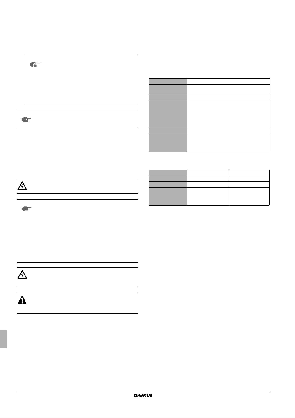
■ Use the following method when installing single core wires.
23
AA'
A'A
3
1
1
1 Single core wire
2 Screw
3 Flat washer
Installation manual
12
■ Use the following method when using round crimp-style
1
2
3
1 Stranded conductor wire
2 Round crimp-style terminal
1 Strip wire end to this point
2
terminals.
3
2
321
B
B
1
1 Round crimp-style terminal
2 Screw
3 Flat washer
4 Pull the connected wire and make sure that it does not
disconnect. Then fix the wires in place in the wire clamp. See
also "Notes to observe" on page 13.
Notes to observe
Observe the notes mentioned below when wiring to the power supply
terminal board.
CAUTION
■ In case the use of stranded conductor wires is
unavoidable for one reason or another, make sure to
install round crimp-style terminals on the tip.
Place the round crimp-style terminal on the wire up to the
covered part and fasten the terminal with the appropriate
tool.
21
■ When connecting the connection wires to the terminal
board using a single core wire, be sure to perform
curling.
Not executing the connections properly may cause heat
and fire.
Strip the wire at terminal block:
Excessive strip length may cause electrical shock
or leakage.
■ When cables are routed from the unit, a protection sleeve
for the conduits (PG-insertions) can be inserted.
3
1 Wire
2 Bush
3 Nut
4 Frame
5 Hose
A Inside
B Outside
AB
1
25
4
When you do not use a wire conduit, be sure to protect
1 Communication wiring
2 Power supply cable
3 Conduit plate
■ Use the specified wire type and connect it securely.
■ Shape wires so that the service panel and cable cover fit
securely (refer to "5.1. Opening the unit" on page 3).
the wires with vinyl tubes to prevent the edge of the hole
from cutting the wires.
■ Follow the electric wiring diagram for electrical wiring
works.
■ Form the wires and fix the cover firmly so that the cover
may be fit in properly.
■ For field wiring use appropriate wire conduits according
to the applicable legislation.
■ Refer to the installation manual attached to the indoor
unit for wiring of indoor unit, etc.
Installation manual
13
Outdoor unit for air to water heat pump
ERLQ018~030BAVJU
4PW62590-1 – 07.2010

14. START-UP AND CONFIGURATION
15. TEST OPERATION
ATTENTION
It is important that all information in this chapter is read
sequentially by the installer and that the system is
configured as applicable.
DANGER: ELECTRICAL SHOCK
See "4. General safety precautions" on page 3.
14.1. Pre-operation checks
After the installation of the unit, first check the following items. Once
all below checks are fulfilled, the unit must be closed, only then can
the unit be powered up.
1 Installation
Check that the unit is properly installed, to avoid abnormal
noises and vibrations when starting up the unit.
2 Electrical wiring
■ Field wiring
Be sure that the field wiring has been carried out according
to the instructions described in the chapter "13. Electric
wiring work" on page 11, according to the wiring diagrams
and according to the applicable legislation.
■ Power supply voltage
Check the power supply voltage on the local supply panel.
The voltage must correspond to the voltage on the
identification label of the unit.
■ Ground wiring
Be sure that the ground wires have been connected properly
and that the ground terminals are tightened.
■ Insulation test of the main power circuit
Using a mega tester for 500 V, check that the insulation
resistance of 2 MΩ or more is attained by applying a voltage
of 500 V DC between power terminals and ground. Never
use the mega tester for the transmission wiring.
■ Fuses, circuit breakers, or protection devices
Check that the fuses, circuit breakers, or the locally installed
protection devices are of the size and type specified in the
chapter "13. Electric wiring work" on page 11. Be sure that
neither a fuse nor a protection device has been bypassed.
■ Internal wiring
Visually check the switch box and the inside of the unit on
loose connections or damaged electrical components.
3 Refrigerant piping
■ Pipe size and pipe insulation
Be sure that correct pipe sizes are installed and that the
insulation work is properly executed.
■ Stop valves
Be sure that the stop valves are open on both liquid and gas
side.
4 Internal unit
■ Damaged equipment
Check the inside of the unit on damaged components or
squeezed pipes.
■ Refrigerant leak
Check the inside of the unit on refrigerant leakage. If there is
a refrigerant leak, call your local dealer. Do not touch any
refrigerant which has leaked out of refrigerant piping
connections. This may result in frostbite.
■ Oil leak
Check the compressor for oil leakage. If there is an oil leak,
call your local dealer.
■ Air inlet/outlet
Check that the air inlet and outlet of the unit is not obstructed
by paper sheets, cardboard, or any other material.
WARNING
■ During tests never pressurize the appliances with a
pressure higher than the maximum allowable
pressure (as indicated on the nameplate of the unit).
■ If refrigerant gas leaks, ventilate the area immediately.
To xic gas may be produced if refrigerant gas comes
into contact with fire.
■ Never directly touch any accidental leaking
refrigerant. This could result in severe wounds caused
by frostbite.
DANGER: DO NOT TOUCH PIPING AND INTERNAL
PA RT S
See "4. General safety precautions" on page 3.
DANGER: ELECTRICAL SHOCK
See "4. General safety precautions" on page 3.
15.1. Test run recommendations
After installation, the installer is obliged to verify correct operation.
Therefore a test run must be performed according to the procedures
described below.
15.2. Maintenance and testing logbook
Provide a logbook and machine card.
In accordance with the applicable legislation, it may be necessary to
provide a logbook with the equipment containing at least: info on
maintenance, repair work, results of tests, stand-by periods, ….
Also, at least, following information shall be provided at an accessible
place of the system:
■ instructions for shutting down the system in case of an
emergency
■ name and address of fire department, police and hospital
■ name, address and day and night telephone numbers for
obtaining service.
NOTE
NOTE
Note that during the first running period of the unit,
required power input may be higher. This phenomenon
originates from the compressor that requires a 50 hour
run elapse before reaching smooth operation and
stable power consumption. Reason is that the moving
parts are made out of iron and that it takes some time
to smooth the surfaces that make contact.
To protect the compressor, be sure to turn on the
power supply 6 hours before starting operation.
ERLQ018~030BAVJU
Outdoor unit for air to water heat pump
4PW62590-1 – 07.2010
Installation manual
14
15.3. Test run
1 Measure the voltage at the primary side of the circuit breaker.
Check that it is 208/230 V.
2 Carry out the test operation in accordance with the indoor
installation manual and operation manual to ensure that all
functions and parts are working properly.
NOTE
■ The unit requires a small amount of power in
its standby mode. If the system is not to be
used for some time after installation, shut off
the circuit breaker to eliminate unnecessary
power consumption.
■ If the circuit breaker trips to shut off the
power to the outdoor unit, the system will
restore the original operation mode when the
power supply is restored.
NOTE
Have the customer actually operate the unit while
looking at the manual included with the indoor unit.
Instruct the customer how to operate the unit correctly.
16. MAINTENANCE AND SERVICE
In order to ensure optimal operation of the unit, a number of checks
and inspections should be carried out on the unit at regular intervals,
preferably yearly.
This maintenance shall be carried out by the installer or service
agent.
DANGER: ELECTRICAL SHOCK
See "4. General safety precautions" on page 3.
NOTE
Touch a metal part by hand (such as the stop valve) in
order to eliminate static electricity and to protect the
PCB before performing service.
■ After measuring the residual voltage, pull out the
outdoor fan connector.
■ The outdoor fan may rotate due to strong
backblow wind, causing the capacitor to charge.
This may result in an electric shock.
After maintenance, make sure the outdoor fan
connector is connected again. Otherwise, the unit may
break down.
18. DISPOSAL REQUIREMENTS
Dismantling of the unit, treatment of the refrigerant, of oil and of other
parts must be done in accordance with relevant local and national
legislation.
19. UNIT SPECIFICATIONS
19.1. Technical specifications
Casing material Painted galvanised steel
Dimensions h x w x d
Weight 126 lbs (57 kg)
Operation range
• cooling (min./max.) 50/109°F (10/43°C)
• heating (min./max.) 5/77°F (–15/25°C)
• domestic hot water
(min./max.)
Refrigerant oil Daphne FVC68D
Piping connection
• liquid 1/4 inch (6.4 mm)
• gas 5/8 inch (15.9 mm)
19.2. Electrical specifications
Phase 1~ 1~
Frequency 60 Hz 60 Hz
Voltage 230 208
Voltage range
• minimum 207 V 187 V
• maximum 253 V 229 V
28.94 x 32.48 x 11.81 inch
(735 x 825 x 300 mm)
5/95°F (–15/35°C)
DANGER: DO NOT TOUCH PIPING AND INTERNAL
PA RT S
See "4. General safety precautions" on page 3.
CAUTION
Do not rinse the outdoor unit. This may cause electric
shocks or fire.
16.1. Service mode operation
Refer to the service manual to carry out any service mode operation.
17. TROUBLESHOOTING
The troubleshooting is described in the installation manual delivered
with the indoor unit.
Installation manual
15
Outdoor unit for air to water heat pump
ERLQ018~030BAVJU
4PW62590-1 – 07.2010
 Loading...