


INSTALLOPERAATIION MANUAL
بيكرتلا ليلد
SPLIT SYSTEM |
Air Conditioner |
|
|
مسقنملا ماظنلا |
ءاوهلا فييكت زاهج |
|
|
|
MODELS |
تلايدوملا |
)فقسلا يف بكريُقفدتلا ددعتم ةبلع عون( |
(Ceiling mounted Multi flow cassette type) |
||
FCQ20EAVAK
FCQ24EAVAK
FCQ36EAVAK
FCQ45EAVAK
READ THESE INSTRUCTIONS CAREFULLY BEFORE INSTALLATION.
KEEP THIS MANUAL IN A HANDY PLACE FOR FUTURE REFERENCE.
.بيكرتلا لبق ةيانعب تاداشرلإا هذه أرقا
.دعب اميف هيلإ عوجرلل هيلإ لوصولا لهسي ناكم يف ليلدلا اذهب ظفتحا
English
E
ةيبرعلا
FCQ20EAVAK |
|
|
FCQ24EAVAK |
SPLIT SYSTEM Air Conditioner |
Installation manual |
FCQ36EAVAK |
|
|
FCQ45EAVAK |
|
|
|
|
|
|
CONTENTS |
|
1. |
SAFETY PRECAUTIONS............................................................................................... |
1 |
2. |
BEFORE INSTALLATION .............................................................................................. |
3 |
3. |
SELECTING INSTALLATION SITE................................................................................ |
6 |
4. |
PREPARATIONS BEFORE INSTALLATION ................................................................. |
8 |
5. |
INDOOR UNIT INSTALLATION ..................................................................................... |
9 |
6. |
REFRIGERANT PIPING WORK .................................................................................. |
10 |
7. |
DRAIN PIPING WORK ................................................................................................. |
13 |
8. |
ELECTRIC WIRING WORK ......................................................................................... |
16 |
9. |
INSTALLATION OF THE DECORATION PANEL.......................................................... |
22 |
10. FIELD SETTING........................................................................................................... |
22 |
|
11. |
TEST OPERATION ...................................................................................................... |
24 |
1. SAFETY PRECAUTIONS
Please read the these " SAFETY CONSIDERATIONS" carefully before installing air conditioning unit and be sure to install it correctly. After completing the installation, make sure that the unit operates properly
during the start-up operation.
Please instruct the customer on how to operate the unit and keep it maintained.Also, inform customers that they should store this installation manual along with the operation manual for
future reference.
Meaning of WARNING and CAUTION notices.
Both are important notices for safety. Be sure to follow them.
WARNING .........Failure to follow these instructions properly may result in personal injury or loss of life.
CAUTION ..........Failure to observe these instructions properly may result in property damage or personal injury, which may be serious depending on the circumstances.
After completing installation, conduct a trial operation to check for faults and explain to the customer how to operate the air conditioner and take care of it with the aid of the operation manual. Ask the customer to store the installation manual along with the operation manual for future reference. This air conditioner comes under the term “appliances not accessible to the general public”.

 WARNING
•Ask your dealer or qualified personnel to carry out installation work.
Do not attempt to install the air conditioner yourself. Improper installation may result in water leakage, electric shocks or fire.
•Install the air conditioner in accordance with the instructions in this installation manual.
Improper installation may result in water leakage, electric shocks or fire.
•When installing the unit in a small room, take measures against to keep refrigerant concentration from exceeding allowable safety limits in the event of refrigerant leakage.
Contact the place of purchase for more information. Excessive refrigerant in a closed ambient can lead to oxygen deficiency
•Be sure to use only the specified accessories and parts for installation work.
Failure to use the specified parts may result in the unit falling, water leakage, electric shocks or fire.
1 |
English |

•Install the air conditioner on a foundation strong enough to withstand the weight of the unit.
A foundation of insufficient strength may result in the equipment falling and causing injury.
•Carry out the specified installation work after taking into account strong winds, typhoons or earthquakes.
Failure to do so during installation work may result in the unit falling and causing accidents.
•Make sure that a separate power supply circuit is provided for this unit and that all electrical work is carried out by qualified personnel according to local laws and regulations and this installation manual.
An insufficient power supply capacity or improper electrical construction may lead to electric shocks or fire.
•Be sure to earth the air conditioner. Do not earth the unit to a utility pipe, lightning conductor or telephone earth lead. Imperfect earthing may result in electric shocks or fire.
A high surge current from lightning or other sources may cause damage to the air conditioner.
•Be sure to install the earth leakage breaker. Failure to install the earth leakage breaker may result in electric shocks or fire.
•Be sure to switch off the unit before touching any electrical parts. Touching a live part may result in electric shock.
•Make sure that all wiring is secured, the specified wires are used, and that there is no strain on the terminal connections or wires. Improper connections or securing of wires may result in abnormal heat build-up or fire.
•When wiring the power supply and connecting the wiring between the indoor and outdoor units, position the wires so that the control box lid can be securely fastened.
Improper positioning of the control box lid may result in electric shocks, fire or overheating terminals.
•If refrigerant gas leaks during installation, ventilate the area immediately. Toxic gas may be produced if the refrigerant comes into contact with fire.
•After completing installation, check for refrigerant gas leakage. Toxic gas may be produced if the refrigerant gas leaks into the room and comes into contact with a source of fire, such as a fan heater, stove or cooker.
•Do not touch any refrigerant that leaks out of refrigerant piping joints or connections. Touching it may cause frostbite.
•Consult your local dealer regarding what to do in case of refrigerant leakage, when the air coditioner is to be installed in a small room, it is necessary to take proper measures so that the amount of any leaked refrigerant does not exceed the concentration limit in the event of leakage. Otherwise, this may lead to an accident due to oxygen depletion.

 CAUTION
•While following the instructions in this installation manual, install drain piping to ensure proper drainage and insulate piping to prevent condensation.
Improper drain piping may result in indoor water leakage and property damage.
•Install the indoor and outdoor units, power cord and connecting wires at least 1 meter away from televisions or radios to prevent picture interference and noise.
(Depending on the incoming signal strength, a distance of 1 meter may not be sufficient to eliminate noise.)
•Install the indoor unit as far away from fluorescent lamps as possible.
Remote controller (wireless kit) transmitting distance can be shorter than expected in rooms with electronic fluorescent lamps (inverter or rapid start types).
•In a domestic environment this product may cause radio interference in which case the user may be required to take adequate measures.
•Do not allow children to climb on the outdoor unit and avoid placing objects on the unit. Injury may result if the unit becomes loose and falls.
•Make sure to provide for adequate measure in order to prevent that the outdoor unit be used as a shelter by small animals.
Small animals making contact with electrical parts can cause malfunctions, smoke or fire. Please instruct the customer to keep the area around the unit clean.
•Install in a machine room that is free of moisture. The unit is designed for indoor use.
•Disposal requirements
Dismantling of the unit, treatment of the refrigerant, of oil and of other parts must be done in accordance with relevant local and national legislation.
English |
2 |

•Do not install the air conditioner in the following locations:
1.Where there is a high concentration of mineral oil spray or vapour (e.g. a kitchen).
Plastic parts will deteriorate, parts may fall off and water leakage could result.
2.Where corrosive gas, such as sulphurous acid gas, is produced. Also areas that are rich in sodium such as seashores.
Corroding of copper pipes or soldered parts may result in refrigerant leakage.
3.Near machinery emitting electromagnetic radiation.
Electromagnetic radiation may disturb the operation of the control system and result in a malfunction of the unit.
4.Where flammable gas may leak, where there is carbon fibre or ignitable dust suspensions in the air, or where volatile flammables such as paint thinner or gasoline are handled.
Operating the unit in such conditions may result in fire.
SPECIAL NOTICE OF PRODUCT
•Refrigerant
•The refrigerant R410A requires that strict Precautions be observed for keeping the system clean,
dry and tightly sealed.
A.Clean and Dry
Strict measure must be taken to keep impurities (including SUNISO oil and other mineral oils as well as moisture) out of the system.
B.Tightly sealed
R410A contains no chlorine, does not destroy the ozone layer and so does not reduce the earth’s protection against harmful ultraviolet radiation. R410A will contribute only slightly to the greenhouse effect if released into the almosphere
•Since design pressure is 4.0 MPa or 40 bar (for R407C units: 3.3MPa or 33bar), the thickness of pipes must be greater than previously. Since R410A is a mixed refrigerant, the required additional refrigerant must be charged in its liquid state. (If the system is charged with refrigerant in its gaseous state, due to composition change, the system will not function normally). The indoor units is designed for R410A use.
See the catalogue for indoor unit models that can be connected. (Normal operation is not possible when connecting units that are originally designed for other refrigerants)
2. BEFORE INSTALLATION
Do not exert pressure on the resin parts when opening the unit or when moving it after opening. Be sure to check the type of R410A refrigerant to be used before doing any work. (Using an incorrect refrigerant will prevent normal operation of the unit.)
•When opening the unit or moving it after opening, be sure to lift it by holding on to the lifting lugs without exerting any pressure on other parts, especially, drain piping, and other resin parts.
•Decide upon a line of transport.
•Leave the unit inside its packaging while moving, until reaching the installation site. Use a sling of soft mate¬rial, where unpacking is unavoidable or protective plates together with a rope when lifting, to avoid damage or scratches to the unit.
•Refer to the installation manual of the outdoor unit for items not described in this manual.
•Do not dispose of any parts necessary for installation until the installation is complete.
•In order to protect the indoor unit from damage, use packing materials to protect the unit after carrying until the installation starts.
•When selecting installation site, refer to the paper pattern.
•Do not use the unit in locations with high salt content in the air such as beachfront property, locations where the voltage fluctuates such as factories, or in automobiles or marine vessels.
3 |
English |
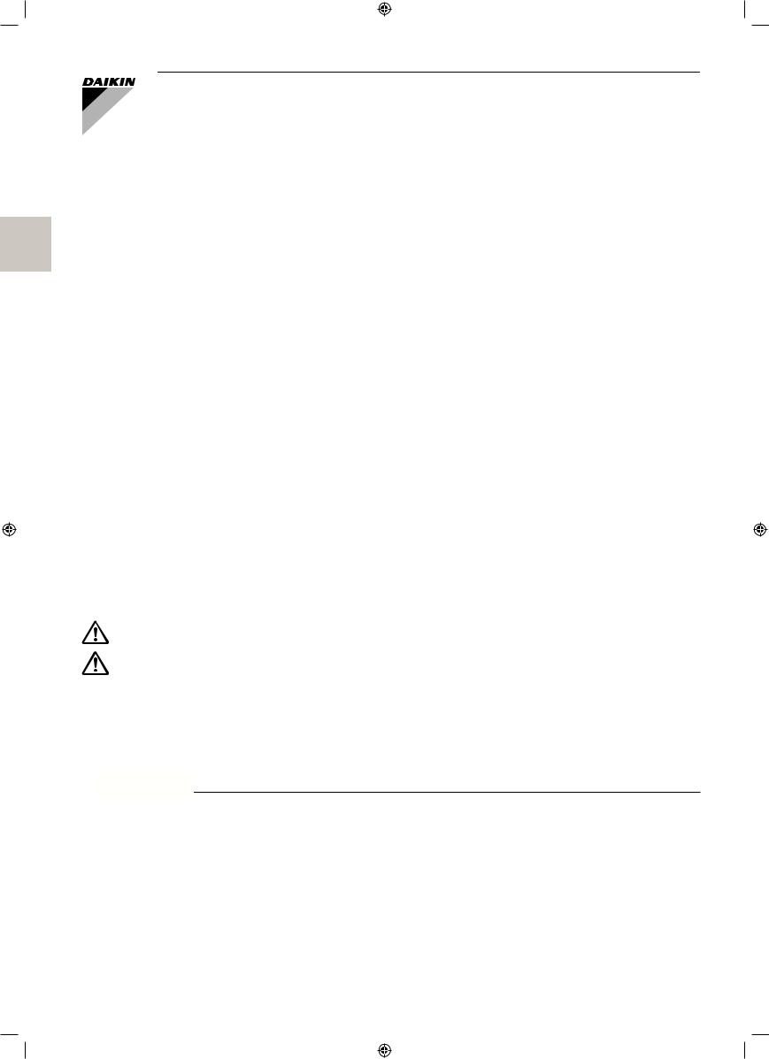
1. ACCESSORIES
Check the following accessories are included with your unit.
Do not dispose of any parts necessary for installation until the installation is completed.
|
|
|
(3) Washer |
|
(5) Paper pattern |
|
|
Name |
(1) Drain hose |
(2) Metal clamp |
for hanger |
(4) Clamp |
(6) Screw (M4) |
||
for installation |
|||||||
|
|
|
bracket |
|
|
|
|
Quantity |
1 pc. |
1 pc. |
8 pcs. |
6 pcs. |
1 pc. |
4 pcs. |
|
|
|
|
|
|
Also used as |
For paper |
|
|
|
|
|
|
pack-ing material |
pattern for |
|
Shape |
|
|
|
|
|
installation |
|
|
|
|
|
|
|
Name |
(7) Washer |
Insulation |
Sealing pad |
|
Installation |
|
|
fixing plate |
forfitting |
|
guide |
|
|||
Quantity |
4 pcs. |
1 each |
1 each |
1 pc. |
1 pc. |
1 pc. |
|
|
|
|
(10) Large |
|
|
|
(Other) |
|
|
(8) for gas |
|
|
|
|
|
|
|
|
|
|
|
|
|
|
|
pipe |
|
(13) Small |
(14) |
|
• Installation |
|
|
|
(11) Medium-1 |
(15) |
manual |
||
Shape |
|
|
|
|
|
• Operation |
|
|
(9) for liquid |
|
|
|
|
||
|
|
|
|
|
|
manual |
|
|
|
pipe |
(12) Medium-2 |
|
|
|
|
|
|
|
|
|
|
|
|
2. OPTIONAL ACCESSORIES
•The optional decoration panel and remote controller are required for this indoor unit.
•Check that the decoration panel is prepared.
(For the installation of the decoration panel, refer to the installation manual attached to the decoration panel.)
unit model |
optional decoration panel |
|
FCQ20·24·36·45EAVAK |
BYCP125K-W1 |
|
Color : White |
||
|
•These are two types of remote controllers: wired and wireless. Select a remote controller according to customer request and install in an appropriate place. (When installing, follow the instructions in the manual included with the remote controller.)
|
Remote controller |
|
wired type |
|
BRC1C61/BRC1D61/BRC1E62 |
wireless type |
|
BRC7F632F |
English |
4 |

FOR THE FOLLOWING ITEMS, TAKE SPECIAL CARE DURING CONSTRUCTION AND CHECK AFTER INSTALLATION IS FINISHED.
a. Items to be checked after completion of work
|
|
|
|
|
Items to be checked |
If not properly done, what is likely to occur |
Check |
|
|
|
|
|
Are the indoor unit and outdoor unit fixed |
The unit may drop, vibrate or make noise. |
|
|
|
|
|
|
firmly? |
|
|
|
|
|
|
|
|
|
|
|
|
|
|
|
Is the outdoor unit fully installed? |
The unit may malfunction or the components |
|
|
|
|
|
|
burn out. |
|
|
|
|
|
|
|
|
|
|
|
|
|
|
|
|
|
|
|
|
|
|
|
Is the gas leak test finished? |
It may result in insufficient cooling or heating. |
|
|
|
|
|
|
Is the unit fully insulated? (Refrigerant piping, |
Condensate water may drip. |
|
|
|
|
|
|
drain piping) |
|
|
|
|
|
|
|
|
||
|
|
|
|
|
Does drainage flow smoothly? |
Condensate water may drip. |
|
|
|
|
|
|
Does the power supply voltage correspond |
The unit may malfunction or the components |
|
|
|
|
|
|
to that shown on the name plate? |
burn out. |
|
|
|
|
|
|
Are wiring and piping correct? |
The unit may malfunction or the components |
|
|
|
|
|
|
burn out. |
|
|
|
|
|
|
|
|
|
|
|
|
|
|
|
Is the unit safely grounded? |
It may result in electric shock. |
|
|
|
|
|
|
Is wiring size according to specifications? |
The unit may malfunction or the components |
|
|
|
|
|
|
burn out. |
|
|
|
|
|
|
|
|
|
|
|
|
|
|
|
Is something blocking the air outlet or inlet |
|
|
|
|
|
|
|
of either the indoor or outdoor units? |
It may result in insufficient cooling or heating. |
|
|
|
|
|
|
(This can lead to malfunction or decreased |
|
|
|
|
|
|
|
|
|
|
|
|
|
|
|
performance due to decreased air volume.) |
|
|
|
|
|
|
|
Does the cold air (warm air) blow properly |
It may result in insufficient cooling or heating. |
|
|
|
|
|
|
during the cooling (heating) operation? |
|
|
|
|
|
|
|
|
|
|
|
|
|
|
|
Are refrigerant piping length and additional |
The refrigerant charge in the system is not |
|
|
|
|
|
|
|
||
|
|
|
|
|
|
||
|
|
|
|
|
refrigerant charge noted down? |
clear. |
|
|
|
|
|
|
Has the field setting done (as necessary)? |
It may result in insufficient cooling or heating. |
|
|
|
|
|
|
b. Items to be checked at time of delivery |
|
|
|
|
|
|
|
* Also review the “1. SAFETY PRECAUTIONS” |
|
|
|
|
|
|
|
Items to be checked |
|
Check |
|
|
|
|
|
Did you attach the control box lid, the air filter, and suction grille? |
|
|
|
|
|
|
|
Did you explain about operations while showing the instruction manual to your customer? |
|
|
|
|
|
|
|
Did you hand the instruction manual over to your customer? |
|
|
|
|
|
|
|
Points for explanation about operations |
|
|
The items with  WARNING and
  CAUTION marks in the instruction manual are the items pertaining to possibilities for bodily injury and material damage in addition to the general usage of the product. Accordingly, it is necessary that you make a full explanation about the described contents and also ask your customers to read the instruction manual.
3. NOTE TO THE INSTALLER
•Be sure to instruct customers how to properly operate the unit (especially cleaning filters, operating different functions, and adjusting the temperature) by having them carry out operations themselves while looking at the manual.
5 |
English |
3. SELECTING INSTALLATION SITE
When opening the unit or moving it after opening, be sure to lift it by holding on to the hanger bracket without exerting any pressure on other parts, especially piping (refrigerant piping and drain piping) and other resin parts. Please attach additional thermal insulation material to the unit body when it is believed that the relative humid¬ity in the ceiling exceeds 80%, temperature 30 C.
Use glass wool, polyethylene foam, or similar with a thickness of 10 mm or more as thermal insulation material.
The direction this product blows can be selected. However, a separately sold shut-off material kit is needed in order to make the unit blow in two, three, or four (corner shut-off) directions.
(1)Select an installation site where the following conditions are fulfilled and that meets your customer’s approval.
•Where optimum air distribution can be ensured.
•Where nothing blocks air passage.
•Where condensate can be properly drained.
•Where the ceiling is strong enough to bear the indoor unit weight.
•Where the false ceiling is not noticeably on an incline.
•Where sufficient clearance for maintenance and service can be ensured.
•Where there is no risk of flammable gas leakage.
•Where piping between indoor and outdoor units is possible within the allowable limit. (Refer to the installation manual for the outdoor unit.)
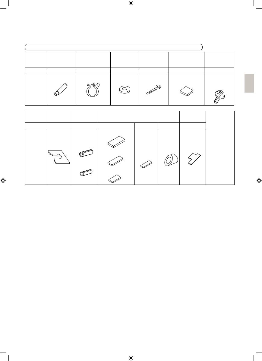
[Space required for installation]
 *≥1500 mm
<![endif]>H
At least 1800mm |
Air |
Air |
Air |
from the floor. |
discharge |
inlet |
discharge |
For installation |
|
|
|
in high places |
|
|
|
|
Floor surface |
|
*≥1500 mm |
|
|
Fig. 1 |
Fig. 2 |
Model |
H (mm) |
|
|
FCQ20·24 |
|
256 |
|
FCQ36·45 |
|
298 |
|

 CAUTION
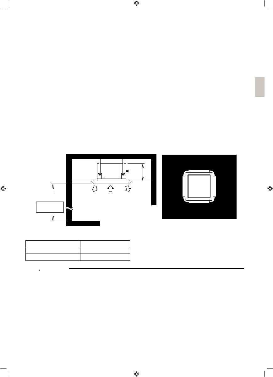
•If there are ventilators, lighting fixtures, or other equipment nearby which might interfere with the air stream, the ceiling might become dirty, so install as per Fig. 3.
•The indoor and outdoor units and the power supply wiring and remote controller cord must be installed at least 1m away from any televisions or radios. This is to prevent interference with picture and sound reception. (Interference may occur even at 1m away depending on the reception quality.)
•If installing the wireless kit, the distance of the signal sent from the remote controller might be shorter if there are fluorescent lights which are electrically started (such as with inverters, rapid starters, etc.) in the room. The indoor unit should be installed as far away from fluorescent lights as possible.
English |
6 |
|
Indoor |
Ventilation |
Indoor |
|
unit |
(NOTE 1) fan |
unit |
|
|
Lighting |
|
At least |
|
At least |
|
|
1500mm |
|
|
1500mm |
*At least |
|
|
from fixtures, |
1500mm from |
At least 2000mm |
|
etc. |
wall(NOTE 2) |
At least 4000mm between indoor units |
|
|
|
||
Fig. 3
NOTE 

1.This applies to exposed lighting (reverse Fuji-type, etc.) only. There are no restrictions regarding embedded lighting which does not protrude from the ceiling.
2.The space marked by the * symbol when the outlet vent is closed must be at least 500mm.
(2)Ceiling height
This product can be installed in ceilings up to 4.2m high.
If the ceiling height is 3.2m or more, field settings will have to be made with the remote controller. See
“10. FIELD SETTING” for details.
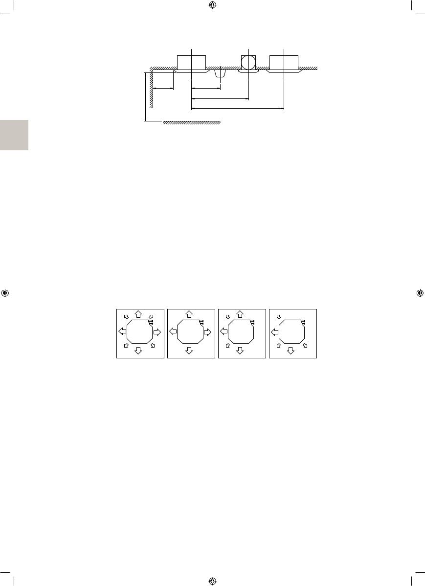
(3)Air direction
The air direction shown in Fig. 4 is an example.
Select the appropriate number of directions according to the shape of the room and the location of the unit. (Field settings have to be made using the remote controller and the outlet vents have to be shut off if two, three, or four (corner shut-off) directions are selected. See the shut-off materials (sold separately) instal¬lation manual for details.)
(4)Use suspension bolts for installation. Check if the location for the installation is strong enough to support the weight of the unit, reinforce it if necessary, and install using suspension bolts. (The spacing of the installation is shown on the “paper pattern for installation (5)”.)
|
[Air direction] |
|
|
| <![if ! IE]> <![endif]>Pipes |
<![if ! IE]> <![endif]>Pipes |
<![if ! IE]> <![endif]>Pipes |
<![if ! IE]> <![endif]>Pipes |
All-round air |
Four air |
Two air |
Three air |
|
direction |
direction |
direction |
|
|
Fig. 4 |
|
7 |
English |
4. PREPARATIONS BEFORE INSTALLATION
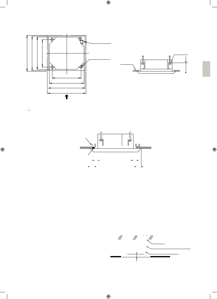
(1) Relation of ceiling opening to unit and suspension bolt position. (Unit: mm)
| <![if ! IE]> <![endif]>(Decoration panel) |
<![if ! IE]> <![endif]>–910 (Ceiling opening) |
<![if ! IE]> <![endif]>840 (Indoor unit) (Suspension bolt pitch) |
| <![if ! IE]> <![endif]>950 |
<![if ! IE]> <![endif]>860 |
<![if ! IE]> <![endif]>780 |
Refrigerant piping
Suspension |
|
bolt (×4) |
False |
|
|
|
ceiling |
Hanger bracket
710(Suspension bolt pitch)
840 (Indoor unit)
860 – 910 (Ceiling opening)
950 (Decoration panel)
View as seen from A
Fig. 6
<![endif]>125 – 130
A |
Fig. 5 |
 CAUTION
Reduce the distance between the unit and ceiling to 35 mm or below in order to maintain an overlapping panel margin of 20 mm for the opening on the ceiling. If the distance exceeds 35 mm, attach a ceiling material to the part marked  or replace the ceiling (see Fig. 7).
Frame |
|
|
Ceiling material |
≥35 |
≥35 |
≤20 |
|
≤20 |
(Ceiling opening dimension) (Ceiling-panel overlapping dimension)
Fig. 7
(2)Make the ceiling opening needed for installation where applicable. (For existing ceilings)
•Refer to the paper pattern for installation (5) for ceiling opening dimensions.
•Create the ceiling opening required for installation. From the side of the opening to the casing outlet, implement the refrigerant and drain piping and wiring for remote controller (unnecessary for wireless type) and indoor-outdoor unit casing outlet. Refer to “6. REFRIGERANT PIPING WORK”, “7. DRAIN
PIPING WORK” and “8. ELECTRIC WIRING WORK”.
•After making an opening in the ceiling, it may be necessary to reinforce ceiling beams to keep the ceiling level and to prevent it from vibrating. Consult the builder for details.
(3)Install the suspension bolts.
Use a hole-in anchor for existing ceilings, and a sunken insert, sunken anchor or other field supplied parts for new ceilings to reinforce the ceiling to bear the weight of the unit. Adjust clearance (50 – 100mm) from the ceiling before proceeding further.
NOTE 

• All the above parts are field supplied.
<installation example>
|
|
|
|
|
|
|
|
|
|
|
|
|
|
Ceiling slab |
||
|
|
|
|
|
|
|
|
|
||||||||
|
|
|
|
<![if ! IE]> <![endif]>100 |
|
|
|
|
|
|
|
|
|
Anchor |
|
|
|
|
|
|
|
|
|
|
|
|
|
|
|
Long nut or turn-buckle |
|||
|
|
|
|
<![if ! IE]> <![endif]>50 – |
|
|
|
|
|
|
|
|
|
|||
|
|
|
|
|
|
|
|
|
|
|
Suspension bolt |
|||||
|
|
|
|
|
|
|
|
|
|
|||||||
|
|
|
|
|
|
|
|
|
|
|
|
|
|
|
|
|
False ceiling
Fig. 8
English |
8 |
5. INDOOR UNIT INSTALLATION
Installing optional accessories (except for the decoration panel) before installing the indoor unit is easier. However, for existing ceilings, install fresh air inlet component kit and branch duct before installing the unit.
As for the parts to be used for installation work, be sure to use the provided accessories and specified parts designated by our company.
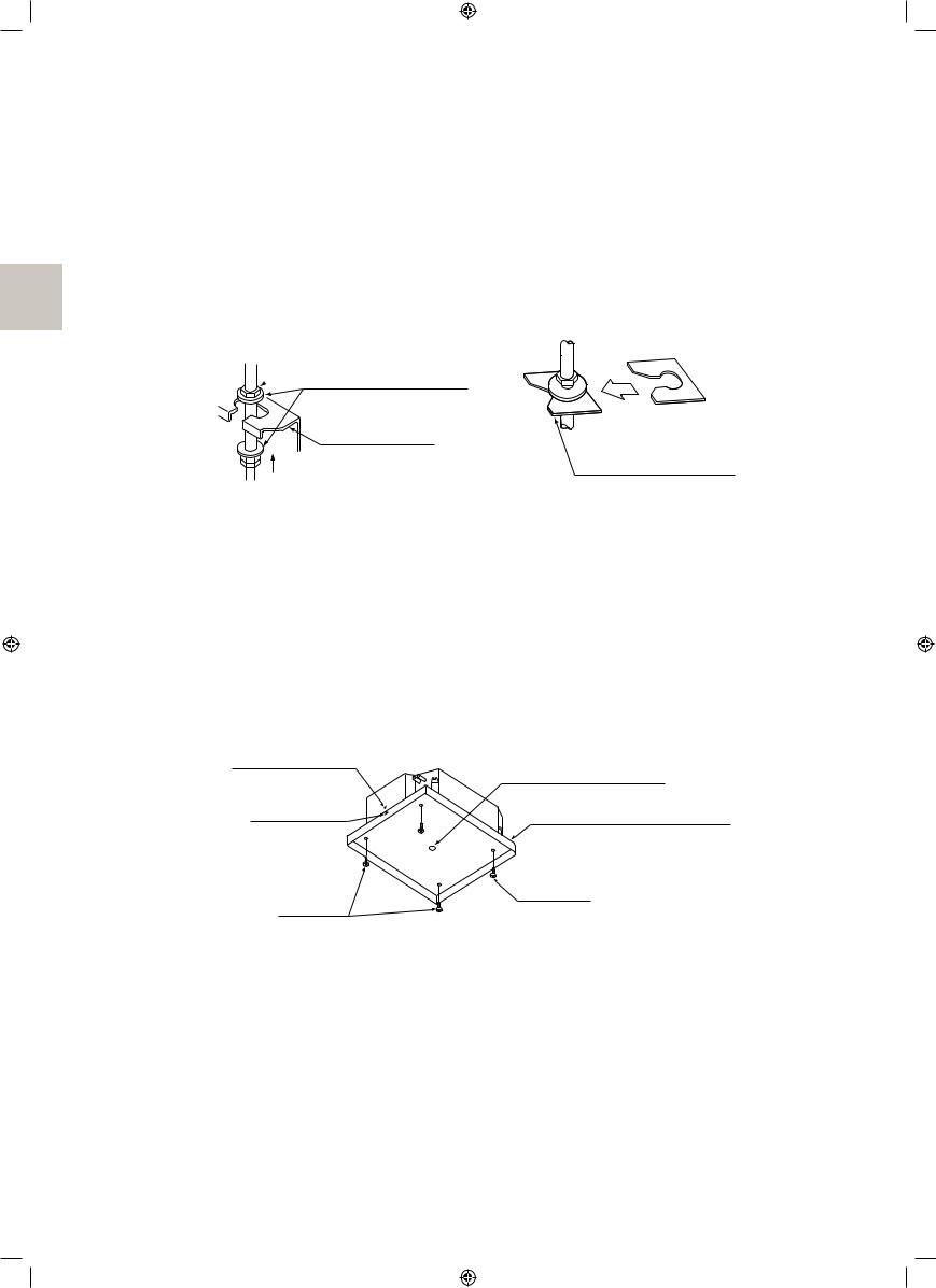
(1) For new ceilings
(1-1) Install the indoor unit temporarily.
•Attach the hanger bracket to the suspension bolt. Be sure to fix it securely by using a nut and washer (3) from the upper and lower sides of the hanger bracket.
The washer fixing plate (7) will prevent the washer from falling.
Field supply
 Washer (3) (accessory)
|
Insert |
Hanger bracket |
|
Tighten |
Washer fixing plate (7) |
(double nuts) |
(accessory) |
[Securing the hanger bracket] |
[Securing the washer] |
Fig. 9 |
Fig. 10 |
(1-2) Refer to the paper pattern for installation (5) for ceiling opening dimension.
Consult the builder or carpenter for details.
•The center of the ceiling opening is indicated on the paper pattern for installation.
The center of the unit is indicated on the triangular mark to the unit bottom and on the paper pattern for installation.
•Fix the paper pattern to the unit with screws (6) (×4).
At this time, fix the paper pattern for installation (5) while aligning the triangular mark on the paper pat¬tern for installation (5) with the triangular mark on the unit main body.
Center of main unit
Center of ceiling opening
Center mark of |
|
main unit |
Paper pattern for installation (5) |
Screw (6) |
Screw (6) |
|
(accessory) |
||
(accessory) |
||
|
Fig. 11
[Installation of paper pattern for installation]
9 |
English |
<Ceiling work>
(1-3) Adjust the unit to the right position for installation.
(Refer to “4. PREPARATIONS BEFORE INSTALLATION-(1)”.)
•Using the Installation guide (15) allows you to check the positions from the underside of the unit to the lower ceiling surface.
Apply the short side of the cutout section.
Lower ceiling |
Underside of |
surface |
the unit |
Installation guide (15) |
|
(accessory) |
Fig. 12 |
|
(1-4) Check the unit is horizontally level.
 CAUTION
•Verify that it is level by using a level or a water-filled vinyl tube. (If the unit is tilted against condensate flow, the float switch may malfunction and cause water to drip.)
(1-5) Remove the washer fixing plate (7) used for preventing the washer from falling and tighten the upper nut.
(1-2) Remove the paper pattern for installation (5).
(2) For existing ceilings
(2-1) Install the indoor unit temporarily.
Perform step (1-1) in (1) For new ceilings.
(2-2) Adjust the height and position of the unit. (Refer to “4.
PREPARATIONS BEFORE INSTALLATION-(1)” and
(1-3) in (1) For new ceilings.)
(2-3) Perform steps (1-4), (1-5) in (1) For new ceilings.
6. REFRIGERANT PIPING WORK
Level |
Vinyl tube |
[Maintaining horizontality]
Fig. 13
‹For refrigerant piping of outdoor units, see the installation manual attached to the outdoor unit.›
‹Execute heat insulation work completely on both sides of the gas piping and the liquid piping. Otherwise, a water leakage can result sometimes.›
‹(When using a heat pump, the temperature of the gas piping can reach up to approximately 120°C, so use insulation which is sufficiently resistant.) ›
‹Also, in cases where the temperature and humidity of the refrigerant piping sections might exceed 30°C or
RH80%, reinforce the refrigerant insulation. (20mm or thicker) Condensate may form on the surface of the insulating material.
‹Be sure to check the type of R410A refrigerant to be used before doing any work. (Using an incorrect refrig-erant will prevent normal operation of the unit.)›

 CAUTION
This product is designed to be used with new refrigerant (R410A). Always observe the precautions on the following when installing.
•Use a pipe cutter and flare suitable for the type of refrigerant.
•Apply ester oil or ether oil around the flare section before connecting.
•Use the flare nut provided to the unit. Do not use a different flare nut (class 1), or otherwise refrigerant leakage may result.
English |
10 |
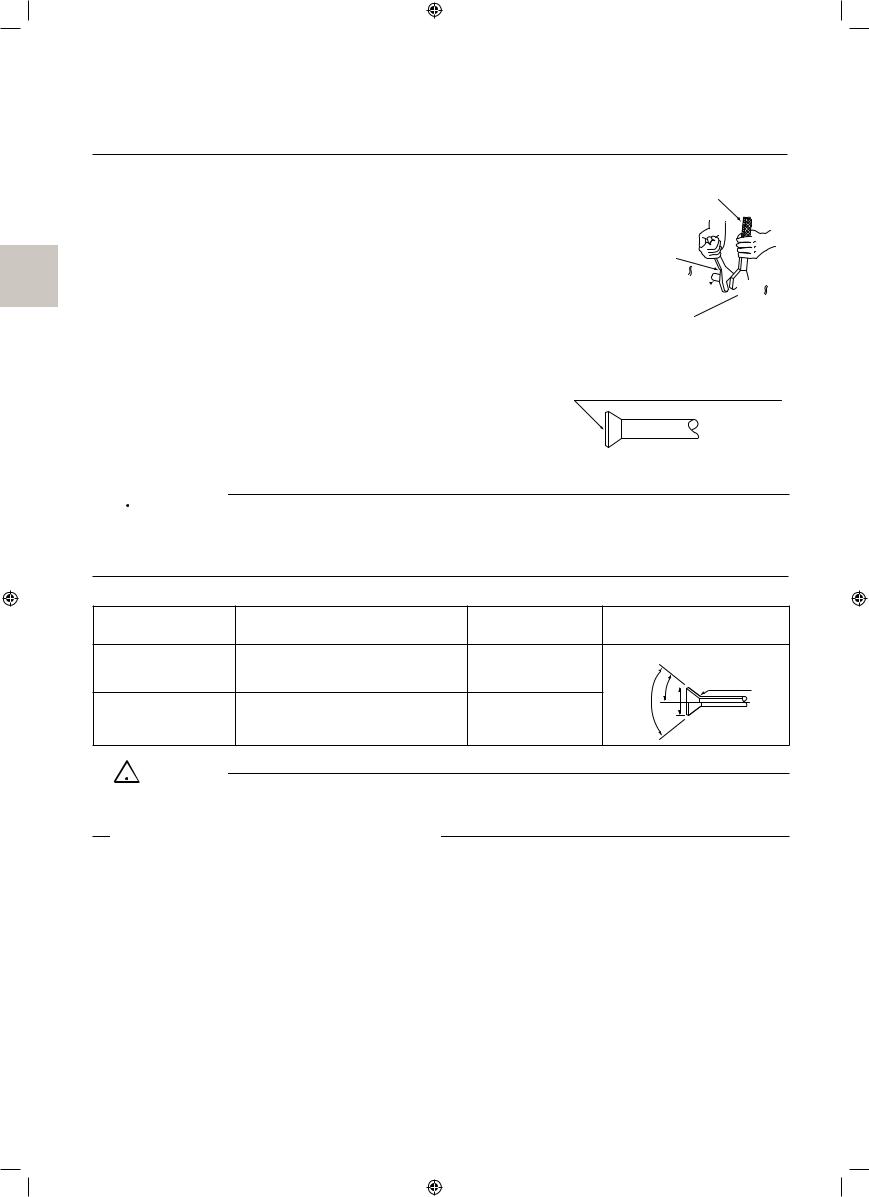
•To prevent dust, moisture or other foreign matter from infiltrating the tube, either pinch the end or cover it with tape.
•Do not allow anything other than the designated refrigerant to get mixed into the refrigerant circuit, such as air, etc. If any refrigerant gas leaks while working on the unit, ventilate the room thoroughly right away.
•The outdoor unit is charged with refrigerant.
•Be sure to use both a spanner and torque wrench together, as shown in the Torque wrench drawing, when connecting or disconnecting pipes to/ from the unit.
(Refer to Fig. 14)
•Refer to “Table 1” for the dimensions of flare nut spaces.
•Use the flare nut included with the unit main body. Spanner
Torque wrench
Spanner
Pipe union 
 Flare nut
•When connecting the flare nut, apply ester oil or ether oil to the flare section (inside only), and spin 3-4 times before screwing in.
(Refer to Fig. 15)

 CAUTION
Fig. 14
Coat here with ester or ether oil.
Fig. 15
•Do not let oil get on the screw holders on the pipe holding plate. Oil can weaken the screw holders.
•Refer to “Table 1” to determine the proper tightening torque.
•Be careful not to damage the flare section.
Table 1
Pipe size |
Tightening torque (N·m) |
Flare dimensions |
|
Flare |
|
A (mm) |
|
||||
|
|
|
|
|
|
Ф 9.5 (3/8”) |
32.7 – 39.9 |
12.8 – 13.2 |
<![if ! IE]> <![endif]>90°±2° |
45°±2° |
R0.4-0.8 |
|
|
|
|
||
Ф 15.9 (5/8”) |
61.8 – 75.4 |
19.3 – 19.7 |
<![if ! IE]> <![endif]>A |
|
|
|
|
|
|||

 CAUTION
• Over-tightening the flare nut may break it and/or cause the refrigerant to leak.
Not recommendable but in case of emergency
You must use a torque wrench but if you are obliged to install the unit without a torque wrench, you may follow the installation method mentioned below.
After the work is finished, make sure to check that there is no gas leak.
When you keep on tightening the flare nut with a spanner, there is a point where the tightening torque suddenly increases. From that position, further tighten the flare nut the angle shown below:
Unless followed the tightening instruction (it is loose tightening), it will lead to the refrigerant leakage (slow leak) and the device malfunction (it does not sufficiently cool or heat).
|
Pipe size |
Further tightening angle |
Recommended arm length of tool |
|
Ф 9.5 (3/8”) |
60 to 90 degrees |
Approx. 200mm |
|
Ф 15.9 (5/8”) |
30 to 60 degrees |
Approx. 300mm |
|
|
|
|
11 |
English |

 CAUTION
For local insulation, be sure to insulate local piping all the way into the pipe connections inside the machine.
Exposed piping may cause condensation or burns on contact.
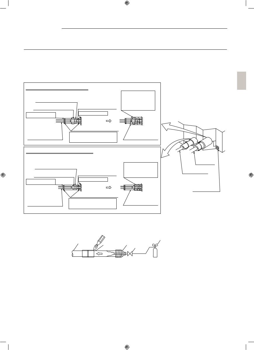
•Make absolutely sure to execute heat insulation works on the pipe-connecting section after checking gas leakage by thoroughly studying the following figure and using the attached heat insulating materials for fitting (8) and (9). (Fasten both ends with the clamps (4).) (Refer to Fig. 16)
•Wrap the sealing pad (11) only around the insulation for the joints on the gas piping side.
(Refer to Fig. 16)
•Always ensure that the joins on the insulating materials for fitting (8) and (9) are facing up.
Gas Piping Insulation Procedure
Insulation for fitting (8)
(accessory) |
Piping insulation |
|
Flare nut connection |
material (main unit) |
|
|
||
Turn seams up |
Attach to base |
|
|
Main unit |
|
Piping insulation |
Clamp (4) (accessory) |
|
material (Field |
Tighten the part other than |
|
supply) |
||
the piping insulation material. |
||
|
Wrap over from the base of the unit to the top of the flare nut connection.
Sealing pad medium-1 (11) (accessory)
Liquid Piping Insulation Procedure
Insulation for fitting (9) |
||
(accessory) |
Piping insulation |
|
|
||
Flare nut connection |
material (main unit) |
|
Attach to base |
||
Turn seams up |
||
Main unit |
||
|
||
Piping insulation |
|
|
material (Field |
Tighten the part other than the |
|
supply) |
||
piping insulation material. |
||
|
||
Wrap the insulator around the part from the root.
Sealing pad medium-2 (12) (accessory)
Gas piping
Liquid piping
Pipe holding plate screw
(2 points)
Fig. 16
•When brazing the refrigerant piping, only begin brazing after having carried out nitrogen substitution or while inserting nitrogen into the refrigerant piping.
Once this is done, connect the indoor unit with a flared or a flanged connection.
Refrigerant |
|
Pressure-reducing |
piping |
Part to |
valve |
|
TapingHands |
|
|
bebrazed |
|
|
Nitrogen |
valve |
|
Nitrogen |
|
|
|
Fig. 17
•Nitrogen should be set to 0.02MPa with a pressure-reducing valve if brazing while inserting nitrogen into the piping. (Refer to Fig. 17)
•Do not use flux when brazing refrigerant piping. Therefore, use the phosphor copper brazing filler metal (BCuP-2: JIS Z 3264/B-Cu93P-710/795: ISO 3677) which does not require flux. (Flux has extremely harmful influence on refrigerant piping systems. For instance, if the chlorine based flux is used, it will cause pipe corrosion or, in particular, if the flux contains fluorine, it will damage the refrigerant oil.)
•When the airtight test is performed for the indoor unit and inter-unit piping after indoor unit installation, be sure to refer to the installation manual for the indoor unit or technical guide for airtight pressurization and refrigerant piping installation.
English |
12 |
•Shortage of refrigerant due to air purge or losing the additional refrigerant charging may cause the failure of the unit (does not sufficiently cool or heat).
Be sure to refer the installation manual or the engineering guide for the outdoor unit at the refrigerant piping work.
 CAUTION
•Do not use anything such as the oxidation inhibitor when brazing. (Residues may result in the clogging pipe or parts damage.)
7. DRAIN PIPING WORK
(1) Rig drain piping
•As for drain work, perform piping in such a manner that water can be drained properly.
•Employ a pipe with either the same diameter or with the diameter larger (excluding the raising section) than that of the connecting pipe (PVC pipe, nominal diameter 25mm, outside diameter 32mm).
•Keep the drain pipe short and sloping downwards at a gradient of at least 1/100 to prevent air pockets from forming.
 CAUTION
Water accumulating in the drain piping can cause the drain to clog.
•If the drain pipe cannot be sufficiently set on a slope, execute the drain raising piping.
•To keep the drain pipe from sagging, space hanging wires every 1 to 1.5m.
Supporting hanger 1–1.5m 1/100 gradient or more |
|
|
GOOD |
WRONG |
Fig. 18-2 |
|
||
|
|
|
Fig. 18-1 |
|
|
•Use the attached drain hose (1) and metal clamp (2).
•Connect the drain hose (1) to the stage part of the drain socket and securely tighten the metal clamp (2) with the tape on the insertion end of the hose. Tighten the screw of the metal clamp (2) until the remainder will become 4mm or less.
Drain socket |
Stage part |
Drain hose (1) |
(accessory) |
Metal clamp (2) |
|
|
VP25 side |
|
(accessory) |
|
|
||
VP20 side |
||||
|
||||
Tape part
Fig. 19
13 |
English |
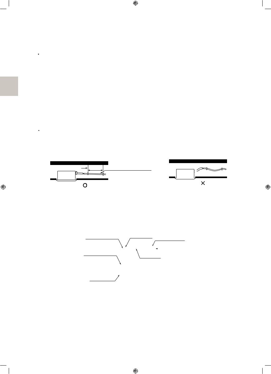
<PRECAUTIONS FOR DRAIN RAISING PIPING>
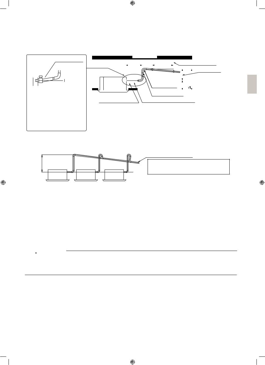
•Install the drain raising pipes at a height of less than 675mm. The drain pump of this unit has a high delivery flow rate. Therefore, the higher the drain raising height is, the lower the sound of draining will be.
For this reason, a minimum drain raising height of 300mm is recommended.
•Install the drain raising pipes at a right angle to the indoor unit and no more than 300mm from the unit.
Drain hose (1) (accessory)
Level 

 or tilted
slightly up
To prevent air bubbles in the drain hose part, keep it level or slightly tilted up. Any bubbles in the hose might cause the unit to make noise due to backflow when the drain pump stops.
Ceiling slab |
|
|
|
|
≤ 300mm |
1 – 1.5m |
Supporting hanger |
||
|
|
|
|
Adjustable |
|
<![if ! IE]> <![endif]>175mm |
<![if ! IE]> <![endif]>850mm |
(≤ 675mm) |
|
|
|
|||
|
Drain raising pipe |
|
|
|
Metal clamp |
Raising section |
|
|
|
(accessroy) (2) |
Drain hose (accessory) (1) |
|
||
|
|
|
|
|
Fig. 20
•To ensure no excessive pressure is applied to the included drain hose (1), do not bend or twist when install¬ing. (This may cause leakage.)
•If converging multiple drain pipes, install according to the procedure shown below.
<![endif]>0 – 675mm
Fig. 21
Converging drain pipes
Keep the drain pipe sloping downward at a gradient of at least 1/100 to prevent air pockets from forming.
( Water pooling in the drainage pipe can(
Select converging drain pipes whose gauge is suitable for the operating capacity of the unit.
(2) After piping work is finished, check if drainage flows smoothly.
WHEN ELECTRIC WIRING WORK IS FINISHED
•Add approximately 1 L of water slowly from the air outlet and check drainage flow. Check drainage flow during COOL running, explained under ‘‘11. TEST OPERATION’’.
•After checking the drainage of water, refer to Fig. 25 and attach the sealing pad (14) to perform the
thermal insulation of the drain socket.
WHEN ELECTRIC WIRING WORK IS NOT FINISHED

 CAUTION
•Electrical wiring work should be done by a certified electrician.
•If someone who does not have the proper qualifications performs the work, perform the following after the test run is complete.
•Remove the control box lid. Connect the single phase power supply (SINGLE PHASE 60Hz 230V) to connections No.1 and No.2 on the terminal block for wiring the units. Do not connect to No.3 of the terminal block for wiring the units. (The drain pump will not operate.) Connect the ground wire firmly.
When carrying out wiring work around the control box, make sure none of the connectors come undone. Be sure to attach the control box lid before turning on the power.
•Put approximately 1L of water slowly into the drain pan through the outlet on the left side of the drain socket. Make sure not to pour water over the drain pump or any electric parts including those of the drain pump.
English |
14 |

•When the power is turned on, the drain pump will operate and you can check the draining of water through the transparent part of the drain socket. (The drain pump will stop automatically in 10 minutes.) After checking the drainage of water, wrap the sealing pad (14) to the drain socket so that thermal insulate the drain socket.
•Do not touch drain pump
•After confirming drainage (Fig. 22, Fig. 23), turn off the power and remove the power supply.
•Attach the control box lid as before.
•Do not connect the drain piping directly to sewage pipes that smell of ammonia. The ammonia in the sewage might enter the indoor unit through the drain pipes and corrode the heat exchanger.
Drain sockets |
|
(Check the |
Drain pump |
drainage now.) |
|
|
location |
least 100mm At Plastic watering can
(Tube should be about 100mm long.)
Service drain outlet (with rubber plug)
(Use this outlet to drain water from the drain pan.)
<Adding water through air discharge outlet>
[Method of adding water] |
Fig. 22 |
|
Transmission wiring terminal block
Power supply single phase 230V
Earth |
|
1 |
2 |
3 |
wire |
|
|||
3 |
2 |
1 |
|
|
Control box lid
Fig. 23
15 |
English |
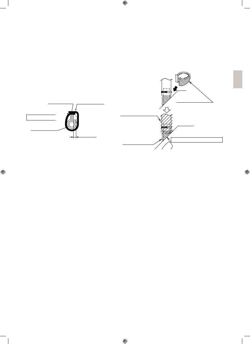
(3)Be sure to install insulation in the locations below as there is a risk that condensation build-up could cause water leakage.
•Drain piping located indoors
•Drain socket
Refer to Fig. 24, 25, and, after checking that water drains properly, install sealing pad (14), ensuring that there are no gaps, and use the sealing pad -large (10) to insulate the drain hose (1) and metal clamp (2) from above.
Large sealing
Metalclamp (2) pad (10) (accessory) (accessory)
Turn seams up 

Drain hose (1)
≥ 4mm
Fig. 24
8. ELECTRIC WIRING WORK
WIRING INSTRUCTIONS
Sealing pad - Large
(10) (accessory)
Be sure to lay the sealing pad (10) on (14).
Sealing pad (14) (accessory)
Sealing pad (14) (accessory)
Do not have the clearance.
Fig. 25
•Electric wiring work must be conducted by electrician authorized by power companies. (Only licensed electrician can conduct electric work and earth connections.)
•All wiring must be performed by an authorized electrician.
•Be sure to install the earth leakage breaker to the outdoor unit.
(This installation of the earth leakage breaker is mandatory for the prevention of electric shocks and fire disasters.)
•Make sure that 230V is specified wiring between the indoor and outdoor units and between indoor units.
•Do not turn on the power supply (of the indoor unit) until all the installation work is completed.
•Be sure to earth the air conditioner.
•Do not connect the earth wire to gas pipes, plumbing pipes, lightning rods, or telephone earth wires.
•Gas pipes: might cause explosions or fire if gas leaks.
•Plumbing: no earth effect if hard vinyl piping is used.
•Telephone earth wires or lightning rods: might cause abnormally high electric potential in the earth during lighting storms.
•For electric wiring work, refer to also “WIRING DIAGRAM” attached to the unit body.
•Never connect the power supply wire to the terminal block for remote controller wire, or otherwise the entire system may be damaged.
•For remote controller wiring details, refer to the installation manual attached to the remote controller.
•Do not touch the printed circuit board ASSY during the wiring work. Otherwise, it may cause damage.
English |
16 |
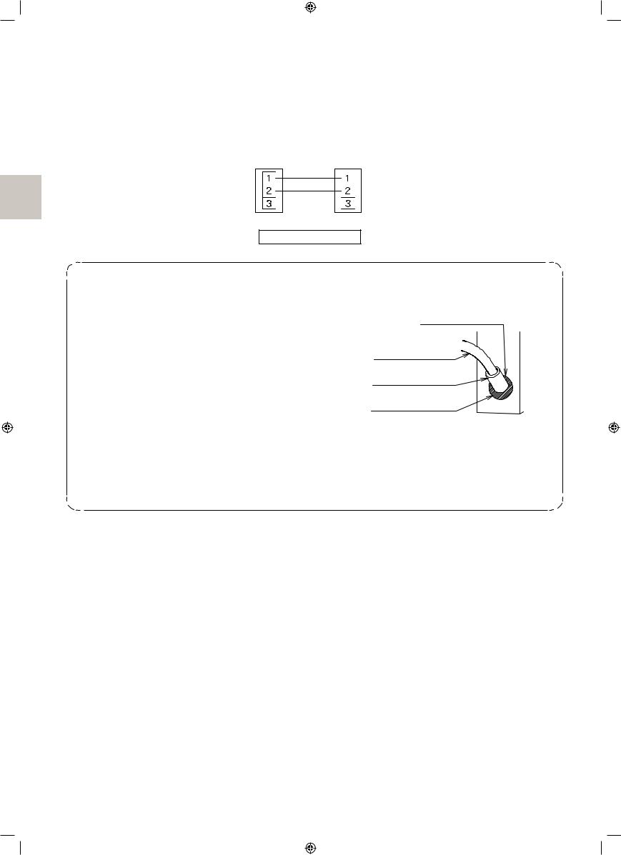
Connection of wiring between units, earth wire and for the remote controller cord (Refer to Fig. 27)
•Wiring the units and earth wire Remove the control box lid and connect wires of matching number to the control block for wiring the units (4P) inside. And connect the earth wire to the earth terminal. In doing this, pull the wires inside through the hole and fix the wires securely with the included clamp (4).
•Remote controller cords Remove the control box lid and pull the wires inside through the hole and connect to the terminal block for remote controller (P1, P2). (no polarity) Securely fix the remote controller cord with the included clamp (4).
Outdoor unit |
Indoor unit |
||||
|
|
|
|
|
|
|
|
|
|
|
|
|
|
|
|
|
|
|
|
|
|
|
|
(Terminal block) |
(Terminal block) |
Match both numbers.
<Connecting wiring between units>
• Protect the wire and the wiring through hole area for wirings of the transmission, earth and the remote controller in order to prevent the intrusion of water and small animals into the air conditioner after the system is wired.
•Halve the sealing pad - small (13), then wind round each one to the respective wiring lines.
•After all the wiring connections are done, fill in any gaps in the through holes with putty or insulation
(procured locally) to prevent small animals and insects from entering the unit from outside. (If any do get in, they could cause short circuits in the control box.)
•Outside the machine, separate the weak wiring
(remote controller cord) and strong wiring (interunit, earth, and other power wiring) at least 50 mm so that they do not pass through the same place together. Proximity may cause electrical interference, malfunctions, and breakage.
[Processing method of wiring through hole]
Wiring through hole
Transmission wire, earth wire or remote controller wire
Sealing pad -
Small (13)
Putty or thermal insulation material
(Filed supply)
Fig. 26
17 |
English |
 Loading...