


 Loading...
INSTALLATION MANUAL
SPLIT SYSTEM Air Conditioners
MODELS
Ceiling suspended type
FHQ18PVJU
FHQ24PVJU
FHQ30PVJU
English
Français
Español
Read these instructions carefully before installation.
Keep this manual in a handy place for future reference.
This manual should be left with the equipment owner.
Lire soigneusement ces instructions avant I’installation. Concerver ce manuel à portée de main pour référence ultérieure.
Ce manuel doit être donné au propriétaire de l’équipement.
Lea cuidadosamente estas instrucciones antes de instalar. Guarde este manual en un lugar a mano para leer en caso de tener alguna duda.
Este manual debe permanecer con el propietario del equipo.
SPLIT SYSTEM Air Conditioners |
Installation manual |
CONTENTS
1.SAFETY CONSIDERATIONS …………………………… 2
2.BEFORE INSTALLATION ………………………………… 3
3.SELECTING INSTALLATION SITE ……………………… 4
4.PREPARATIONS BEFORE INSTALLATION …………… 5
5.INDOOR UNIT INSTALLATION…………………………… 6
6.REFRIGERANT PIPING WORK ………………………… 7
7.DRAIN PIPING WORK …………………………………… 9
8.ELECTROLLER ………………………………………… 10
9.WIRING EXAMPLE AND HOW TO SET THE REMOTE CONTROLLER ………………………………………… 10
10.ATTACHING THE SUCTION GRILLE, THE DECORATION PANELS AND THE PROTECTION NET ……………… 12
11.FIELD SETTING ………………………………………… 12
12.TEST OPERATION ……………………………………… 13
1.SAFETY CONSIDERATIONS
Please read these “SAFETY CONSIDERATIONS” carefully before installing air conditioning equipment and be sure to install it correctly. After completing the installation, make sure that the unit operates properly during the start-up operation. Please instruct the customer on how to operate the unit and keep it maintained.
Also, inform customers that they should store this installation manual along with the operation manual for future reference. This air conditioner comes under the term “appliances not accessible to the general public”.
Meaning of danger, warning, caution and note symbols.
DANGER …………Indicates an iminenfly hazardous situation which, if not avoided, will result in death or serious injury.
WARNING …………lndicates a potentially hazardous situation which, if not avoided, could result in death or serious injury.
CAUTION …………lndicates a potentially hazardous situation which, if not avoided,may resulf in minor or moderate injury. lt may also be sued to alert against unsafe practices.
NOTE ………………lndicates situation that may result in equipment or property-damage-only accidents.

 DANGER
•Do not ground units to water pipes, telephone wires or lightning rods because incomplete grounding could cause a severe shock hazard resulting in severe injury or death, and to gas pipes because a gas leak could result in an explosion which could lead to severe injury or death.
•Do not install unit in an area where flammable materials are present due to risk of explosion resulting in serious injury or death.
•Refrigerant gas is heavier than air and displaces oxygen. A massive leak could lead to oxygen depletion, especially in basements, and an asphyxiation hazard could occur leading to serious injury or death.
•If the refrigerant gas leaks during installation, ventilate the area immediately.
Refrigerant gas may produce toxic gas if it comes in contact with fire such as from a fan, heater, stove or cooking device. Exposure to this gas could result in severe injury or death.
•After completing the installation work, check that the refrigerant gas does not leak.
Refrigerant gas may produce toxic gas if it comes in contact with fire such as from a fan, heater, stove or cooking device. Exposure to this gas could result in severe injury or death.
•Safely dispose of the packing materials.
Packing materials, such as nails and other metal or wooden parts, may cause stabs or other injuries. Tear apart and throw away plastic packaging bags so that children will not play with them. Children playing with plastic bags face the danger of death by suffocation.

 WARNING
•Ask your dealer or qualified personnel to carry out installation work. Do not try to install the air conditioner by yourself.
Improper installation may result in water leakage, electric shocks or fire.
•Perform installation work in accordance with this installation manual.
Improper installation may result in water leakage, electric shocks or fire.
•Be sure to use only the specified accessories and parts for installation work.
Failure to use the specified parts may result in water leakage, electric shocks, fire or the unit falling.
•Install the air conditioner on a foundation strong enough to withstand the weight of the unit.
A foundation of insufficient strength may result in the equipment falling and causing injuries.
•Carry out the specified installation work after considering strong winds, typhoons or earthquakes.
Improper installation work may result in the equipment falling and causing accidents.
•Make sure that a separate power supply circuit is provided for this unit and that all electrical work is carried out by qualified personnel according to local laws and regulations and this installation manual.
An insufficient power supply capacity or improper electrical construction may lead to electric shocks or fire.
•Make sure that all wiring is secured, the specified wires are used, and no external forces act on the terminal connections or wires.
Improper connections or installation may result in fire.
•When wiring the power supply and connecting the remote controller wire and transmission wire, position the wires so that the control box lid can be securely fastened.
Improper positioning of the control box lid may result in electric shocks, fire or the terminals overheating.
2 |
English |
•Before touching electrical parts, turn off the unit.
•Do not touch the switch with wet fingers.
Touching a switch with wet fingers can cause electric shock.
•Be sure to install an earth leakage breaker.
Failure to install an earth leakage breaker may result in electric shocks, or fire.
•Do not install the air conditioner in the following locations :
(a)where a mineral oil mist or an oil spray or vapor is produced, for example in a kitchen.
Plastic parts may deteriorate and fall off or result in water leakage.
(b)where corrosive gas, such as sulfurous acid gas, is produced.
Corroding copper pipes or soldered parts may result in refrigerant leakage.
(c)near machinery emitting electromagnetic waves. Electromagnetic waves may disturb the operation of the control system and result in a malfunction of the equipment.
•Refrigerant pipes may be very hot or very cold during or immediately after operation.
Touching them could result in burns or frostbite. To avoid injury give the pipes time to return to normal temperature or, if you must touch them, be sure to wear proper gloves.

 CAUTION
•Install drain pipe in order to ensure proper drainage and do the thermal insulation of the pipe in order to prevent condensate.
Improper drain pipe may result in water leakage and property damage.
•Be very careful about product transportation.
Some products use PP bands for packaging. Do not use any PP bands for a means of transportation. It is dangerous.
•Safely dispose of the packing materials.
Packing materials, such as nails and other metal or wooden parts, may cause stabs or other injuries.
Tear apart and throw away plastic packaging bags so that children will not play with them. If children play with a plastic bag which was not torn apart, they face the risk of suffocation.
•Do not turn off the power immediately after stopping operation.
Always wait at least 5 minutes before turning off the power. Otherwise, water leakage and trouble may occur.
•Make sure to provide for adequate measures in order to prevent that the outdoor unit be used as a shelter by small animals.
Small animals making contact with electrical parts can cause malfunctions, smoke or fire. Please instruct the customer to keep the area around the unit clean.

 NOTE
NOTE
•Install the indoor and outdoor units, power supply wire and transmission wire at least 3.5 ft. away from televisions or radios in order to prevent image interference or noise.
(Depending on the radio waves, a distance of 3.5 ft. may not be sufficient enough to eliminate the noise.)
•Remote controller (wireless kit) transmitting distance can result shorter than expected in rooms with electronic fluorescent lamps. (inverter or rapid start types)
Install the indoor unit as far away from fluorescent lamps as possible.
•In a domestic environment this product may cause radio interference in which case the user may be required to take adequate measures.
•Dismantling of the unit, treatment of the refrigerant, oil and eventual other parts, should be done in accordance with the relevant local and national regulations.
2.BEFORE INSTALLATION
•When moving the unit while removing it from the packing case, be sure to lift it by the four hanger brackets. Avoid putting any pressure on other parts especially the refrigerant piping.
•Be sure to check the type of refrigerant to be used before installing the unit. (Using an incorrect refrigerant will prevent normal operation of the unit.)
•The accessories needed for installation must be retained in your custody until the installation work is completed. Do not discard them!
•Decide upon a line of transport.
•Leave the unit inside its packaging while moving, until reaching the installation site. Where unpacking is unavoidable, use a sling of soft material or protective plates together with a rope when lifting, to avoid damage or scratches to the unit.
•When selecting installation site, refer to the paper pattern.
•For the installation of an outdoor unit, refer to the installation manual attached to the outdoor unit.
•Do not install or operate the unit in rooms mentioned below.
•Laden with mineral oil, or filled with oil vapor or spray like in kitchens. (Plastic parts may deteriorate which could eventually cause the unit to fall out of place, or could lead to leaks.)
•Where corrosive gas like sulfurous gas exists.
•(Copper tubing and brazed spots may corrode which could eventually lead to refrigerant leaks.)
•Where machines can generate electromagnetic waves. (Control system may malfunction.)
•Where the air contains high levels of salt such as that near the ocean and where voltage fluctuates greatly such as that in factories. Also in vehicles or vessels.
•This unit, both indoor and outdoor, is suitable for installation in a commercial and light industrial environment.
If installed as a household appliance it could cause electromagnetic interference.

 WARNING
•Entrust installation to the place of purchase or a qualified person. Improper installation could lead to leak and, in worse cases, electric shock of fire.
•Use of unspecified parts could lead to the unit falling, leaks and, in worse cases, electric shock or fire.

 NOTE
NOTE
•Be sure to read this manual before installing the indoor unit.
•Be sure to mount an air filter (part to be procured in the field) in the suction air passage in order to prevent water leaking, etc.
English |
3 |
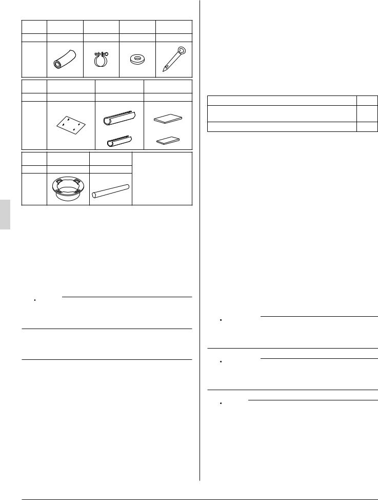
2-1 ACCESSORIES
Check the following accessories are included with your unit.
Name |
(1) Drain pipe (2) Metal |
(3) Washer for |
(4) Clamp |
|
|
|
clamp |
hanger bracket |
|
Quantity |
1 pc. |
1 pc. |
8 pcs. |
9 pcs. |
Shape |
|
|
|
|
Name |
(5) Paper pattern |
Insulation pipe |
Sealing pad |
|
for installation |
cover |
|
||
|
|
|
||
Quantity |
1 pc. |
1 each |
1 each |
|
|
|
(6) For gas pipe |
(8) Large |
|
|
|
|
|
|
Shape |
|
(7) For liquid pipe |
(9) Small |
|
|
|
|||
Name |
(10) Resin bush |
(11) Insulating |
|
|
|
|
tube |
|
|
Quantity |
1 pc. |
3 pcs. |
(Other) |
|
|
|
For wire |
|
|
|
|
• Operation manual |
||
Shape |
|
|
• Installation manual |
|
|
|
|
|
|
2-2 OPTIONAL ACCESSORIES
•The remote controller are required for this indoor unit in Table 1.
•These are 2 types of remote controllers : wired and wireless. Select a remote controller according to customer request and install in an appropriate place.
Table 1
Remote controller |
|
|
|
Wired type |
BRC1C71 |
|
|
Wireless type |
BRC7E83 |
|
|

 NOTE
NOTE
•If you wish to use a remote controller that is not listed in “Table 1” on page 4, select a suitable remote controller after consulting catalogs and technical materials.
FOR THE FOLLOWING ITEMS, TAKE SPECIAL CARE DURING CONSTRUCTION AND CHECK AFTER INSTALLATION IS FINISHED.
a. Items to be checked after completion of work
Items to be checked |
If not properly done, what is |
Check |
|
likely to occur |
|||
|
|
||
|
|
|
|
Are the indoor and outdoor |
The units may drop, vibrate or |
|
|
unit fixed firmly? |
make noise. |
|
|
|
|
|
|
Is the gas leak test finished? |
It may result in insufficient |
|
|
cooling. |
|
||
|
|
||
|
|
|
|
Is the unit fully insulated? |
Condensate water may drip. |
|
|
|
|
|
|
Does drainage flow smoothly? |
Condensate water may drip. |
|
|
|
|
|
|
Does the power supply volt- |
The unit may malfunction or |
|
|
age correspond to that shown |
|
||
the components burn out. |
|
||
on the name plate? |
|
|
|
Are wiring and piping correct? |
The unit may malfunction or |
|
|
the components burn out. |
|
||
|
|
|
Is the unit safely grounded? |
It may result in electric shock. |
|
|
|
|
Is wiring size according to |
The unit may malfunction or |
|
specifications? |
the components burn out. |
|
|
|
|
Is something blocking the air |
It may result in insufficient |
|
outlet or inlet of either the |
|
|
cooling. |
|
|
indoor or outdoor units? |
|
|
|
|
|
|
|
|
Are refrigerant piping length |
The refrigerant charge in the |
|
and additional refrigerant |
|
|
system is not clear. |
|
|
charge noted down? |
|
|
|
|
|
|
|
|
b.Items to be checked at time of delivery
Also review the “SAFETY CONSIDERATIONS”
Items to be checked |
Check |
Did you explain about operations while showing the operation manual to your customer?
Did you hand the instruction manual over to your customer?
2-3 NOTE TO THE INSTALLER
Be sure to instruct customers how to properly operate the unit (especially cleaning filters, operating different functions, and adjusting the temperature) by having them carry out operations themselves while looking at the manual.
3.SELECTING INSTALLATION SITE
Please attach additional insulation pipe cover to the unit body when it is believed that the relative humidity in the ceiling exceeds 80%. Use glass wool, polyethylene foam, or similar with a thickness of 3/8 in.. or more as insulation pipe cover.
(1)Select an installation site where the following conditions are fulfilled and that meets your customer’s approval.
•Where optimum air distribution can be ensured.
•Where nothing blocks air passage.
•Where condensate can be properly drained.
•Where the ceiling is strong enough to bear the indoor unit weight.
•Where the false ceiling is not noticeably on an incline.
•Where sufficient clearance for maintenance and service can be ensured.

 DANGER
•Do not install unit in an area where flammable materials are present due to the risk explosion resulting in serious injury or death.

 WARNING
•If the supporting structural members are not strong enough to take the unit’s weight, the unit could fall out of place and cause serious injury.

 NOTE
NOTE
•When a margin is in the space of the section, service and maintenance work will become still easier if it vacates 7 7/8 in. or more.
4 |
English |

|
|
|
|
|
|
|
|
|
|
|
|
|
|
|
|
|
|
|
|
|
|
|
|||||||||||||||||||||||||||
1 3/16 or more |
|
|
|
|
|
|
|
|
|
|
|
|
|
|
|
|
|
1 3/16 or more |
|||||||||||||||||||||||||||||||
|
|
|
|
|
|
|
|
|
|
|
|
|
|
|
|
|
|
|
|
|
|
|
|
|
|
|
|
|
|
|
|
|
|
|
|
|
|
|
|
|
|
|
|
|
|
|
|
|
|
|
|
|
|
|
|
|
|
|
|
|
|
|
|
|
|
|
|
|
|
|
|
|
|
|
|
|
|
|
|
|
|
|
|
|
|
|
|
|
|
|
|
|
|
|
|
|
|
|
|
|
|
|
|
|
|
|
|
|
|
|
|
|
|
|
|
|
|
|
|
|
|
|
|
|
|
|
|
|
|
|
|
|
|
|
|
|
|
|
|
|
|
|
|
|
|
|
|
|
|
|
|
|
|
|
|
|
|
|
|
|
|
|
|
|
|
|
|
|
|
|
|
|
|
|
|
|
|
|
|
|
|
|
|
|
|
|
|
|
|
|
|
|
|
|
|
|
|
|
|
Air outlet |
more |
|
Required service |
||
Air inlet |
||
space |
12or |
|
Obstruction |
||
|
Floor |
|
|
(Length : in.) |
|
•Where pipe between indoor and outdoor units is possible within the allowable limit.
(Refer to the installation manual for the outdoor unit.)
•Install the indoor and outdoor units, power wire and connecting wires at least 3.5 ft. away from televisions or radios in order to prevent image interference or noise. (Depending on the radio waves, a distance of 3.5 ft. may not be sufficient enough to eliminate the noise.)
(2)Use suspension bolts for installation. Check whether the ceiling is strong enough to support the weight of the unit or not. If there is a risk, reinforce the ceiling before installing the unit.
(Installation pitch is marked on the paper pattern for installation. Refer to it to check for points requiring reinforcing.)
(3)This product may be installed on ceilings up to 10.6 ft. from the floor.
(4)A direction of installation.
•Refrigerant piping : the rear side, right side or upper part.
•Wiring : only the rear side.
•Drain piping : the rear right side or the right side.
(As the rear left, installation is impossible.)
4.PREPARATIONS BEFORE INSTALLATION
(1)Relation of holes for indoor unit, suspension bolt position, piping and wiring.
|
|
Wiring hole Rear side pipe hole |
|
26 1/8 |
6 1/4 |
||
|
|
33/4 |
|
Front view |
6 |
5/8 |
|
|
5 |
|
|
|
|
|
|
|
22 |
|
|
|
|
|
Conduit |
Drain pipe hole |
|
|
25 3/4 |
|
|
|
|
|
|
||
|
|
|
|
|
hole |
|
|||
|
27 11/16 |
|
|
|
|
||||
|
|
|
|
|
|
||||
62 5/8 (Indoor unit) |
|
|
|
||||||
61 (Suspension bolt pitch) |
|
|
|
||||||
|
|
27 3/16 |
1/4 |
1/4 |
|
|
|
|
|
|
|
24 5/8 |
6 7 |
|
|
8 1/4 |
|
||
unit) |
|
|
|
|
(Indoor3/4 |
1/410 (Suspension pitch)bolt |
False ceiling view |
|
Top gas pipe hole |
|
|
|
||
|
|
|
|
|
26 |
|
|
|
Suspension bolt (× 4) |
|
|
Top liquid pipe hole |
||
|
|
|
||
|
|
Air outlet |
|
(length : in.) |
(2)Make holes for suspension bolts, refrigerant and drain pipe, and wire.
•Refer to the paper pattern for installation.
•Select the location for each of holes and open the holes in the ceiling.
(3)Remove the parts from the indoor unit.
(3-1) Detach the suction grille.
•Slide the locking knobs (×2) on the suction grille inward (direction of arrows) and lift upwards. (Refer to Fig. 1)
•With the suction grille open, remove the suction grille forward, holding on to the rear tabs (×2) on the suction grille.
(Refer to Fig. 2)
Knob |
Suction grille |
Fig. 1
Tab
Suction grille
Fig. 2
(3-2) Remove the decoration panels (left and right) and the protection net.
•After removing the securing screws for the decoration panels (one each), pull them forward (in the direction of the arrow) and remove them. (Refer to Fig. 3)
•Remove the securing screws for the protection net.
(Refer to Fig. 3)
Protection net |
securing screws (M4) |
|
Decoration panel |
Decoration panel |
securing screws (M4) |
|
|
securing screw |
Decoration |
(M4) |
panel |
Decoration panel |
Fig. 3 |
•Raise one side of the protection net upwards (in the direction of the arrow (i)) and remove back (the arrow (ii)).
(Refer to Fig. 4, 5)
•Take out the accessories.
(ii)
Accessories
Protection net
(i)
Decoration panel
Fig. 4
Decoration panel
English |
5 |
Loading...