


 Loading...
Installation and operation
manual
Split system air conditioners
FFA25A2VEB |
|
|
FFA35A2VEB |
Installation and operation manual |
|
|
||
FFA50A2VEB |
English |
|
FFA60A2VEB |
Split system air conditioners |
|
CE - DECLARATION-OF-CONFORMITY |
CE - DECLARACION-DE-CONFORMIDAD |
CE - DECLARAÇÃO-DE-CONFORMIDADE |
CE - ERKLÆRING OM-SAMSVAR |
CE - IZJAVA-O-USKLAĐENOSTI |
CE - IZJAVA O SKLADNOSTI |
CE - ATITIKTIES-DEKLARACIJA |
CE - KONFORMITÄTSERKLÄRUNG |
CE - DICHIARAZIONE-DI-CONFORMITA |
CE - ЗАЯВЛЕНИЕ-О-СООТВЕТСТВИИ |
CE - ILMOITUS-YHDENMUKAISUUDESTA |
CE - MEGFELELŐSÉGI-NYILATKOZAT |
CE - VASTAVUSDEKLARATSIOON |
CE - ATBILSTĪBAS-DEKLARĀCIJA |
CE - DECLARATION-DE-CONFORMITE |
CE - ΔHΛΩΣΗ ΣΥΜΜΟΡΦΩΣΗΣ |
CE - OVERENSSTEMMELSESERKLÆRING |
CE - PROHLÁŠENÍ-O-SHODĚ |
CE - DEKLARACJA-ZGODNOŚCI |
CE - ДЕКЛАРАЦИЯ-ЗА-СЪОТВЕТСТВИЕ |
CE - VYHLÁSENIE-ZHODY |
CE - CONFORMITEITSVERKLARING |
|
CE - FÖRSÄKRAN-OM-ÖVERENSTÄMMELSE |
|
CE - DECLARAŢIE-DE-CONFORMITATE |
|
CE - UYGUNLUK-BEYANI |
Daikin Industries Czech Republic s.r.o.
01  declares under its sole responsibility that the air conditioning models to which this declaration relates:
02  erklärt auf seine alleinige Verantwortung daß die Modelle der Klimageräte für die diese Erklärung bestimmt ist: 03
  déclare sous sa seule responsabilité que les appareils d'air conditionné visés par la présente déclaration:
04  verklaart hierbij op eigen exclusieve verantwoordelijkheid dat de airconditioning units waarop deze verklaring betrekking heeft: 05
  declara baja su única responsabilidad que los modelos de aire acondicionado a los cuales hace referencia la declaración:
06  dichiara sotto sua responsabilità che i condizionatori modello a cui è riferita questa dichiarazione:
07  δηλώνει με αποκλειστική της ευθύνη ότι τα μοντέλα των κλιματιστικών συσκευών στα οποία αναφέρεται η παρούσα δήλωση: 08
  declara sob sua exclusiva responsabilidade que os modelos de ar condicionado a que esta declaração se refere:
09 |
заявляет, исключительно под свою ответственность, что модели кондиционеров воздуха, к которым относится настоящее заявление: |
17 |
deklaruje na własną i wyłączną odpowiedzialność, że modele klimatyzatorów, których dotyczy niniejsza deklaracja: |
10 |
erklærer under eneansvar, at klimaanlægmodellerne, som denne deklaration vedrører: |
18 |
declară pe proprie răspundere că aparatele de aer condiţionat la care se referă această declaraţie: |
11 |
deklarerar i egenskap av huvudansvarig, att luftkonditioneringsmodellerna som berörs av denna deklaration innebär att: |
19 |
z vso odgovornostjo izjavlja, da so modeli klimatskih naprav, na katere se izjava nanaša: |
12 |
erklærer et fullstendig ansvar for at de luftkondisjoneringsmodeller som berøres av denne deklarasjon, innebærer at: |
20 |
kinnitab oma täielikul vastutusel, et käesoleva deklaratsiooni alla kuuluvad kliimaseadmete mudelid: |
13 |
ilmoittaa yksinomaan omalla vastuullaan, että tämän ilmoituksen tarkoittamat ilmastointilaitteiden mallit: |
21 |
декларира на своя отговорност, че моделите климатична инсталация, за които се отнася тази декларация: |
14 |
prohlašuje ve své plné odpovědnosti, že modely klimatizace, k nimž se toto prohlášení vztahuje: |
22 |
visiška savo atsakomybe skelbia, kad oro kondicionavimo prietaisų modeliai, kuriems yra taikoma ši deklaracija: |
15 |
izjavljuje pod isključivo vlastitom odgovornošću da su modeli klima uređaja na koje se ova izjava odnosi: |
23 |
ar pilnu atbildību apliecina, ka tālāk uzskaitīto modeļu gaisa kondicionētāji, uz kuriem attiecas šī deklarācija: |
16 |
teljes felelőssége tudatában kijelenti, hogy a klímaberendezés modellek, melyekre e nyilatkozat vonatkozik: |
24 |
vyhlasuje na vlastnú zodpovednosť, že tieto klimatizačné modely, na ktoré sa vzťahuje toto vyhlásenie: |
|
|
25 |
tamamen kendi sorumluluǧunda olmak üzere bu bildirinin ilgili olduǧu klima modellerinin aşaǧıdaki gibi olduǧunu beyan eder: |
FFA25A2VEB, FFA35A2VEB, FFA50A2VEB, FFA60A2VEB,
01 are in conformity with the following standard(s) or other normative document(s), provided that these are used in accordance with our instructions:
02 der/den folgenden Norm(en) oder einem anderen Normdokument oder -dokumenten entspricht/entsprechen, unter der Voraussetzung, daß sie gemäß unseren Anweisungen eingesetzt werden:
03 sont conformes à la/aux norme(s) ou autre(s) document(s) normatif(s), pour autant qu'ils soient utilisés conformément à nos instructions:
04conform de volgende norm(en) of één of meer andere bindende documenten zijn, op voorwaarde dat ze worden gebruikt overeenkomstig onze instructies:
05 están en conformidad con la(s) siguiente(s) norma(s) u otro(s) documento(s) normativo(s), siempre que sean utilizados de acuerdo con nuestras instrucciones:
06 sono conformi al(i) seguente(i) standard(s) o altro(i) documento(i) a carattere normativo, a patto che vengano usati in conformità alle nostre istruzioni:
07είναι σύμφωνα με το(α) ακόλουθο(α) πρότυπο(α) ή άλλο έγγραφο(α) κανονισμών, υπό την προϋπόθεση ότι χρησιμοποιούνται σύμφωνα με τις οδηγίες μας:
08estão em conformidade com a(s) seguinte(s) norma(s) ou outro(s) documento(s) normativo(s), desde que estes sejam utilizados de acordo com as nossas instruções:
09соответствуют следующим стандартам или другим нормативным документам, при условии их использования согласно нашим инструкциям:
10overholder følgende standard(er) eller andet/andre retningsgivende dokument(er), forudsat at disse anvendes i henhold til vore instrukser:
11respektive utrustning är utförd i överensstämmelse med och följer följande standard(er) eller andra normgivande dokument, under förutsättning att användning sker i överensstämmelse med våra instruktioner:
12respektive utstyr er i overensstemmelse med følgende standard(er) eller andre normgivende dokument(er), under forutssetning av at disse brukes i henhold til våre instrukser:
13vastaavat seuraavien standardien ja muiden ohjeellisten dokumenttien vaatimuksia edellyttäen, että niitä käytetään ohjeidemme mukaisesti:
14za předpokladu, že jsou využívány v souladu s našimi pokyny, odpovídají následujícím normám nebo normativním dokumentům:
15u skladu sa slijedećim standardom(ima) ili drugim normativnim dokumentom(ima), uz uvjet da se oni koriste u skladu s našim uputama:
16megfelelnek az alábbi szabvány(ok)nak vagy egyéb irányadó dokumentum(ok)nak, ha azokat előírás szerint használják:
17spełniają wymogi następujących norm i innych dokumentów normalizacyjnych, pod warunkiem że używane są zgodnie z naszymi instrukcjami:
18sunt în conformitate cu următorul (următoarele) standard(e) sau alt(e) document(e) normativ(e), cu condiţia ca acestea să fie utilizate în conformitate cu instrucţiunile noastre:
19skladni z naslednjimi standardi in drugimi normativi, pod pogojem, da se uporabljajo v skladu z našimi navodili:
20on vastavuses järgmis(t)e standardi(te)ga või teiste normatiivsete dokumentidega, kui neid kasutatakse vastavalt meie juhenditele:
21съответстват на следните стандарти или други нормативни документи, при условие, че се използват съгласно нашите инструкции:
22atitinka žemiau nurodytus standartus ir (arba) kitus norminius dokumentus su sąlyga, kad yra naudojami pagal mūsų nurodymus:
23tad, ja lietoti atbilstoši ražotāja norādījumiem, atbilst sekojošiem standartiem un citiem normatīviem dokumentiem:
24sú v zhode s nasledovnou(ými) normou(ami) alebo iným(i) normatívnym(i) dokumentom(ami), za predpokladu, že sa používajú v súlade s našim návodom:
25ürünün, talimatlarımıza göre kullanılması koşuluyla aşağıdaki standartlar ve norm belirten belgelerle uyumludur:
EN60335-2-40,
01 |
following the provisions of: |
10 |
under iagttagelse af bestemmelserne i: |
19 |
ob upoštevanju določb: |
|
|
01 |
Directives, as amended. |
10 |
Direktiver, med senere ændringer. |
18 |
Directivelor, cu amendamentele respective. |
02 |
gemäß den Vorschriften der: |
11 |
enligt villkoren i: |
20 |
vastavalt nõuetele: |
|
|
02 |
Direktiven, gemäß Änderung. |
11 |
Direktiv, med företagna ändringar. |
19 |
Direktive z vsemi spremembami. |
03 |
conformément aux stipulations des: |
12 |
gitt i henhold til bestemmelsene i: |
21 |
следвайки клаузите на: |
Machinery 2006/42/EC |
** |
03 |
Directives, telles que modifiées. |
12 |
Direktiver, med foretatte endringer. |
20 |
Direktiivid koos muudatustega. |
04 |
overeenkomstig de bepalingen van: |
13 |
noudattaen määräyksiä: |
22 |
laikantis nuostatų, pateikiamų: |
04 |
Richtlijnen, zoals geamendeerd. |
13 |
Direktiivejä, sellaisina kuin ne ovat muutettuina. |
21 |
Директиви, с техните изменения. |
||
05 |
siguiendo las disposiciones de: |
14 |
za dodržení ustanovení předpisu: |
23 |
ievērojot prasības, kas noteiktas: |
Electromagnetic Compatibility 2014/30/EU |
* |
05 |
Directivas, según lo enmendado. |
14 |
v platném znění. |
22 |
Direktyvose su papildymais. |
06 |
secondo le prescrizioni per: |
15 |
prema odredbama: |
24 |
održiavajúc ustanovenia: |
Low Voltage 2014/35/EU |
|
06 |
Direttive, come da modifica. |
15 |
Smjernice, kako je izmijenjeno. |
23 |
Direktīvās un to papildinājumos. |
07 |
με τήρηση των διατάξεων των: |
16 |
követi a(z): |
25 |
bunun koşullarına uygun olarak: |
|
07 |
Οδηγιών, όπως έχουν τροποποιηθεί. |
16 |
irányelv(ek) és módosításaik rendelkezéseit. |
24 |
Smernice, v platnom znení. |
|
08 |
de acordo com o previsto em: |
17 |
zgodnie z postanowieniami Dyrektyw: |
|
|
|
|
08 |
Directivas, conforme alteração em. |
17 |
z późniejszymi poprawkami. |
25 |
Değiştirilmiş halleriyle Yönetmelikler. |
09 |
в соответствии с положениями: |
18 |
în urma prevederilor: |
|
|
|
|
09 |
Директив со всеми поправками. |
|
|
|
|
01 Note* |
as set out in <A> and judged positively by <B> |
06 Nota* |
delineato nel <A> e giudicato positivamente da <B> |
11 Information* |
enligt <A> och godkänts av <B> enligt |
16 Megjegyzés* |
a(z) <A> alapján, a(z) <B> igazolta a megfelelést, a(z) |
21 Забележка* |
както е изложено в <A> и оценено положително от <B> |
|
|
02 Hinweis* |
according to the Certificate <C>. |
07 Σημείωση* |
secondo il Certificato <C>. |
12 Merk* |
Certifikatet <C>. |
17 Uwaga* |
<C> tanúsítvány szerint. |
22 Pastaba* |
съгласно Сертификата <C>. |
|
|
wie in <A> aufgeführt und von <B> positiv |
όπως καθορίζεται στο <A> και κρίνεται θετικά |
som det fremkommer i <A> og gjennom positiv |
zgodnie z dokumentacją <A>, pozytywną |
kaip nustatyta <A> ir kaip teigiamai nuspręsta <B> pagal |
|
|
|||||
|
beurteilt gemäß Zertifikat <C>. |
|
από το <B> σύμφωνα με το Πιστοποιητικό <C>. |
|
bedømmelse av <B> ifølge Sertifikat <C>. |
|
opinią <B> i Świadectwem <C>. |
|
Sertifikatą <C>. |
|
|
03 Remarque* |
tel que défini dans <A> et évalué positivement par <B> 08 Nota* |
tal como estabelecido em <A> e com o parecer positivo |
13 Huom* |
jotka on esitetty asiakirjassa <A> ja jotka <B> |
18 Notă* |
aşa cum este stabilit în <A> şi apreciat pozitiv de <B> |
23 Piezīmes* |
kā norādīts <A> un atbilstoši <B> pozitīvajam vērtējumam |
<A> |
DAIKIN.TCF.033A3/03-2017 |
|
|
conformément au Certificat <C>. |
|
de <B> de acordo com o Certificado <C>. |
|
on hyväksynyt Sertifikaatin <C> mukaisesti. |
|
în conformitate cu Certificatul <C>. |
|
saskaņā ar sertifikātu <C>. |
||
04 Bemerk* |
zoals vermeld in <A> en positief beoordeeld door <B> 09 Примечание* |
как указано в <A> и в соответствии с положительным |
14 Poznámka* |
jak bylo uvedeno v <A> a pozitivně zjištěno |
19 Opomba* |
kot je določeno v <A> in odobreno s strani <B> |
24 Poznámka* |
ako bolo uvedené v <A> a pozitívne zistené <B> v súlade |
<B> |
DEKRA (NB0344) |
|
|
overeenkomstig Certificaat <C>. |
|
решением <B> согласно Свидетельству <C>. |
|
<B> v souladu s osvědčením <C>. |
|
v skladu s certifikatom <C>. |
|
s osvedčením <C>. |
||
05 Nota* |
como se establece en <A> y es valorado |
10 Bemærk* |
som anført i <A> og positivt vurderet af <B> i henhold til |
15 Napomena* |
kako je izloženo u <A> i pozitivno ocijenjeno od strane 20 Märkus* |
nagu on näidatud dokumendis <A> ja heaks kiidetud |
25 Not* |
<A>’da belirtildiği gibi ve <C> Sertifikasına göre <B> |
<C> |
2178265.0551-EMC |
|
|
positivamente por <B> de acuerdo con el |
|
Certifikat <C>. |
|
<B> prema Certifikatu <C>. |
|
<B> järgi vastavalt sertifikaadile <C>. |
|
tarafından olumlu olarak değerlendirildiği gibi. |
|
|
Certificado <C>.
01** DICz*** is authorised to compile the Technical Construction File.
02** DICz*** hat die Berechtigung die Technische Konstruktionsakte zusammenzustellen. 03** DICz*** est autorisé à compiler le Dossier de Construction Technique.
04** DICz*** is bevoegd om het Technisch Constructiedossier samen te stellen. 05** DICz*** está autorizado a compilar el Archivo de Construcción Técnica. 06** DICz*** è autorizzata a redigere il File Tecnico di Costruzione.
***DICz = Daikin Industries Czech Republic s.r.o.
07** Η DICz*** είναι εξουσιοδοτημένη να συντάξει τον Τεχνικό φάκελο κατασκευής. 08** A DICz*** está autorizada a compilar a documentação técnica de fabrico.
09** Компания DICz*** уполномочена составить Комплект технической документации.
10** DICz*** er autoriseret til at udarbejde de tekniske konstruktionsdata.
11** DICz*** är bemyndigade att sammanställa den tekniska konstruktionsfilen. 12** DICz*** har tillatelse til å kompilere den Tekniske konstruksjonsfilen.
13** DICz*** on valtuutettu laatimaan Teknisen asiakirjan.
14** Společnost DICz*** má oprávnění ke kompilaci souboru technické konstrukce. 15** DICz*** je ovlašten za izradu Datoteke o tehničkoj konstrukciji.
16** A DICz*** jogosult a műszaki konstrukciós dokumentáció összeállítására.
17** DICz*** ma upoważnienie do zbierania i opracowywania dokumentacji konstrukcyjnej. 18** DICz*** este autorizat să compileze Dosarul tehnic de construcţie.
19** DICz*** je pooblaščen za sestavo datoteke s tehnično mapo. 20** DICz*** on volitatud koostama tehnilist dokumentatsiooni.
21** DICz*** е оторизирана да състави Акта за техническа конструкция.
22** DICz*** yra įgaliota sudaryti šį techninės konstrukcijos failą. 23** DICz*** ir autorizēts sastādīt tehnisko dokumentāciju.
24** Spoločnosť DICz*** je oprávnená vytvoriť súbor technickej konštrukcie. 25** DICz*** Teknik Yapı Dosyasını derlemeye yetkilidir.
1A-3P480520
Tetsuya Baba
Managing Director
Plzen, 2nd of May 2017

Table of contents
Table of contents |
|
12.2.3 About the heating operation......................................... |
16 |
|
|
12.2.4 To operate the system ................................................. |
16 |
||
|
12.3 |
Using the dry program................................................................ |
16 |
|
|
|
12.3.1 About the dry program ................................................. |
16 |
|
1 About the documentation |
3 |
12.3.2 To use the dry program................................................ |
16 |
|
Adjusting the air flow direction |
16 |
|||
1.1 About this document |
12.4 |
|||
3 |
12.4.1 About the air flow flap |
16 |
||
|
|
For the installer |
4 |
||
2 |
About the box |
4 |
|
|
2.1 |
Indoor unit ................................................................................. |
4 |
|
|
2.1.1 To remove the accessories from the indoor unit......... |
4 |
3 |
About the units and options |
4 |
|
|
3.1 |
About the indoor unit ................................................................. |
4 |
|
3.2 |
System layout............................................................................ |
5 |
4 |
Preparation |
5 |
|
|
4.1 |
Preparing installation site .......................................................... |
5 |
|
|
4.1.1 Installation site requirements of the indoor unit .......... |
5 |
5 |
Installation |
5 |
|
|
5.1 |
Mounting the indoor unit............................................................ |
5 |
|
|
5.1.1 Precautions when mounting the indoor unit................ |
5 |
|
|
5.1.2 Guidelines when installing the indoor unit................... |
5 |
|
|
5.1.3 Guidelines when installing the drain piping................. |
6 |
|
5.2 |
Connecting the refrigerant piping .............................................. |
8 |
|
|
5.2.1 About connecting the refrigerant piping ...................... |
8 |
|
|
5.2.2 Precautions when connecting the refrigerant piping ... |
8 |
|
|
5.2.3 Guidelines when connecting the refrigerant piping ..... |
8 |
|
|
5.2.4 Pipe bending guidelines.............................................. |
9 |
|
|
5.2.5 To flare the pipe end ................................................... |
9 |
|
|
5.2.6 To braze the pipe end ................................................. |
9 |
|
|
5.2.7 To connect the refrigerant piping to the indoor unit .... |
9 |
|
5.3 |
Connecting the electrical wiring................................................. |
9 |
|
|
5.3.1 About connecting the electrical wiring......................... |
10 |
|
|
5.3.2 Precautions when connecting the electrical wiring ..... |
10 |
|
|
5.3.3 Guidelines when connecting the electrical wiring ....... |
10 |
|
|
5.3.4 Specifications of standard wiring components............ |
10 |
|
|
5.3.5 To connect the electrical wiring on the indoor unit...... |
10 |
6 |
Configuration |
11 |
|
|
6.1 |
Field settings ............................................................................. |
11 |
7 |
Commissioning |
11 |
|
|
7.1 |
Overview: Commissioning......................................................... |
11 |
|
7.2 |
Precautions when commissioning ............................................. |
11 |
|
7.3 |
Checklist before commissioning................................................ |
12 |
|
7.4 |
To perform a test run................................................................. |
12 |
|
7.5 |
Error codes when performing a test run .................................... |
13 |
8 |
Disposal |
13 |
|
9 |
Technical data |
13 |
|
|
9.1 |
Piping diagram: Indoor unit ....................................................... |
13 |
|
9.2 |
Wiring diagram .......................................................................... |
14 |
|
|
||
For the user |
15 |
||
10 |
About the system |
15 |
|
|
10.1 |
System layout............................................................................ |
15 |
13 Maintenance and service |
17 |
13.1Cleaning the air filter, suction grille, air outlet and outside
panels ........................................................................................ |
|
17 |
13.1.1 |
To clean the air filter .................................................... |
17 |
13.1.2 |
To clean the suction grille ............................................ |
17 |
13.1.3 |
To clean the air outlet and outside panels ................... |
18 |
13.2 Maintenance after a long stop period ......................................... |
18 |
|
13.3 Maintenance before a long stop period ...................................... |
18 |
|
13.4 About the refrigerant................................................................... |
18 |
|
13.5 After-sales service and warranty ................................................ |
19 |
|
13.5.1 |
Warranty period ........................................................... |
19 |
13.5.2 |
Recommended maintenance and inspection............... |
19 |
13.5.3 |
Recommended maintenance and inspection cycles.... |
19 |
13.5.4 |
Shortened maintenance and replacement cycles ........ |
19 |
14 Troubleshooting |
20 |
|
14.1 Symptoms that are NOT system malfunctions ........................... |
20 |
|
14.1.1 |
Symptom: The system does not operate ..................... |
20 |
14.1.2 |
Symptom: The fan strength does not correspond to |
|
|
the setting .................................................................... |
20 |
14.1.3 |
Symptom: The fan direction does not correspond to |
|
|
the setting .................................................................... |
20 |
14.1.4 |
Symptom: White mist comes out of a unit (Indoor |
|
|
unit) .............................................................................. |
21 |
14.1.5 |
Symptom: White mist comes out of a unit (Indoor |
|
|
unit, outdoor unit) ......................................................... |
21 |
14.1.6 |
Symptom: The user interface display reads "U4" or |
|
|
"U5" and stops, but then restarts after a few minutes.. |
21 |
14.1.7 |
Symptom: Noise of air conditioners (Indoor unit)......... |
21 |
14.1.8 |
Symptom: Noise of air conditioners (Indoor unit, |
|
|
outdoor unit)................................................................. |
21 |
14.1.9 |
Symptom: Noise of air conditioners (Outdoor unit) ...... |
21 |
14.1.10 |
Symptom: Dust comes out of the unit .......................... |
21 |
14.1.11 |
Symptom: The units can give off odours...................... |
21 |
14.1.12 |
Symptom: The outdoor unit fan does not spin ............. |
21 |
14.1.13 |
Symptom: The display shows "88"............................... |
21 |
14.1.14 |
Symptom: The compressor in the outdoor unit does |
|
|
not stop after a short heating operation ....................... |
21 |
15 Relocation |
|
21 |
16 Disposal |
|
21 |
1 About the documentation
1.1About this document
Target audience
Authorised installers + end users
INFORMATION
This appliance is intended to be used by expert or trained users in shops, in light industry, and on farms, or for commercial and household use by lay persons.
11 |
User interface |
15 |
Documentation set |
||
12 |
Operation |
15 |
|||
This document is part of a documentation set. The complete set |
|||||
|
12.1 |
Operation range ........................................................................ |
15 |
consists of: |
|
|
12.2 |
Operating the system ................................................................ |
16 |
|
|
|
|
12.2.1 About operating the system ........................................ |
16 |
|
|
12.2.2About cooling, heating, fan only, and automatic
operation ..................................................................... |
16 |
FFA25~60A2VEB |
Installation and operation manual |
Split system air conditioners |
|
4P456960-1 – 2017.03 |
3 |

2 About the box
▪General safety precautions:
▪Safety instructions that you must read before installing
▪Format: Paper (in the box of the indoor unit)
▪Indoor unit installation and operation manual:
▪Installation and operation instructions
▪Format: Paper (in the box of the indoor unit)
▪Installer and user reference guide:
▪Preparation of the installation, good practices, reference data,…
▪Detailed step-by-step instructions and background information for basic and advanced usage
▪Format: Digital files on http://www.daikineurope.com/support- and-manuals/product-information/
Latest revisions of the supplied documentation may be available on the regional Daikin website or via your dealer.
The original documentation is written in English. All other languages are translations.
Technical engineering data
▪A subset of the latest technical data is available on the regional Daikin website (publicly accessible).
▪The full set of latest technical data is available on the Daikin extranet (authentication required).
For the installer
2 About the box
2.1Indoor unit
2.1.1To remove the accessories from the indoor unit
a |
b |
c |
d |
e |
f |
|
1× |
1× |
8× |
4× |
7× |
g |
h |
i |
1× |
4× |
1× |
j k
 1×
1×  1×
1×
aPaper pattern for installation (upper part of packing)
bGeneral safety precautions
cIndoor unit installation and operation manual
dWashers for hanger bracket
eScrews
fCable ties
gMetal clamp
hSealing pads: Large (drain pipe), medium 1 (gas pipe), medium 2 (liquid pipe), small (electrical wiring)
iDrain hose
jInsulation piece: Small (liquid pipe)
kInsulation piece: Large (gas pipe)
3 About the units and options
3.1About the indoor unit
Use the system in the following temperature and humidity ranges for safe and effective operation.
For combination with R410A outdoor unit, refer to the following table:
Outdoor units |
|
Cooling |
Heating |
RR71~125 |
Outdoor |
–15~46°C DB |
— |
|
temperature |
|
|
|
Indoor |
18~37°C DB |
— |
|
temperature |
12~28°C WB |
|
|
|
|
|
RQ71~125 |
Outdoor |
–5~46°C DB |
–9~21°C DB |
|
temperature |
|
–10~15°C WB |
|
|
|
|
|
Indoor |
18~37°C DB |
10~27°C DB |
|
temperature |
12~28°C WB |
|
|
|
|
|
|
|
|
|
RXS25~60 |
Outdoor |
–10~46°C DB |
–15~24°C DB |
|
temperature |
|
–16~18°C WB |
|
|
|
|
|
Indoor |
18~32°C DB |
10~30°C DB |
|
temperature |
|
|
2MXS50 |
Outdoor |
10~46°C DB |
–15~24°C DB |
|
temperature |
|
–16~18°C WB |
|
|
|
|
|
Indoor |
18~32°C DB |
10~30°C DB |
|
temperature |
|
|
3MXS40~68 |
Outdoor |
–10~46°C DB |
–15~24°C DB |
4MXS68~80 |
temperature |
|
–16~18°C WB |
|
|
||
5MXS90 |
Indoor |
18~32°C DB |
10~30°C DB |
|
temperature |
|
|
RZQG71~140 |
Outdoor |
–15~50°C DB |
–19~21°C DB |
|
temperature |
|
–20~15.5°C WB |
|
|
|
|
|
Indoor |
18~37°C DB |
10~27°C DB |
|
temperature |
12~28°C WB |
|
|
|
|
|
|
|
|
|
RZQSG71~140 |
Outdoor |
–15~46°C DB |
–14~21°C DB |
|
temperature |
|
–15~15.5°C WB |
|
|
|
|
|
Indoor |
20~37°C DB |
10~27°C DB |
|
temperature |
14~28°C WB |
|
|
|
|
|
|
|
|
|
RZQ200~250 |
Outdoor |
–5~46°C DB |
–14~21°C DB |
|
temperature |
|
–15~15°C WB |
|
|
|
|
|
Indoor |
20~37°C DB |
10~27°C DB |
|
temperature |
14~28°C WB |
|
|
|
|
For combination with R32 outdoor unit, refer to the following table:
Installation and operation manual |
FFA25~60A2VEB |
4 |
Split system air conditioners |
4P456960-1 – 2017.03 |
Outdoor units |
|
Cooling |
Heating |
RXM25~60 |
Outdoor |
–10~46°C DB |
–15~24°C DB |
|
temperature |
|
–16~18°C WB |
|
|
|
|
|
|
|
|
|
Indoor |
18~32°C DB |
10~30°C DB |
|
temperature |
|
|
2MXM50 |
Outdoor |
–10~46°C DB |
–15~24°C DB |
3MXM40~68 |
temperature |
|
–16~18°C WB |
|
|
||
|
|
|
|
4MXM68~80 |
Indoor |
18~32°C DB |
10~30°C DB |
5MXM90 |
temperature |
|
|
|
|
|
|
|
|
|
|
RZAG71~140 |
Outdoor |
–20~52°C DB |
–19.5~21°C DB |
|
temperature |
|
–20~15.5°C WB |
|
|
|
|
|
Indoor |
18~37°C DB |
10~27°C DB |
|
temperature |
12~28°C WB |
|
|
|
|
|
|
|
|
|
RZASG71~140 |
Outdoor |
–15~46°C DB |
–14~21°C DB |
|
temperature |
|
–15~15.5°C WB |
|
|
|
|
|
Indoor |
20~37°C DB |
10~27°C DB |
|
temperature |
14~28°C WB |
|
|
|
|
|
Indoor humidity |
≤80%(a) |
||
|
|
|
|
(a)To avoid condensation and water dripping out of the unit. If the temperature or the humidity is beyond these conditions, safety devices may be put in action and the air conditioner may not operate.
4 Preparation
4 Preparation
4.1Preparing installation site
4.1.1Installation site requirements of the indoor unit
INFORMATION
The sound pressure level is less than 70 dBA.
CAUTION
Appliance not accessible to the general public, install it in a secured area, protected from easy access.
This unit, both indoor and outdoor, is suitable for installation in a commercial and light industrial environment.
▪ Spacing. Mind the following requirements:
a |
b |
c |
a |
d |
|
C |
|
≥1500 |
A ≥1500 |
≥1500 |
|
≥2000 |
|
|
|
|
B |
|
≥4000 |
|
|
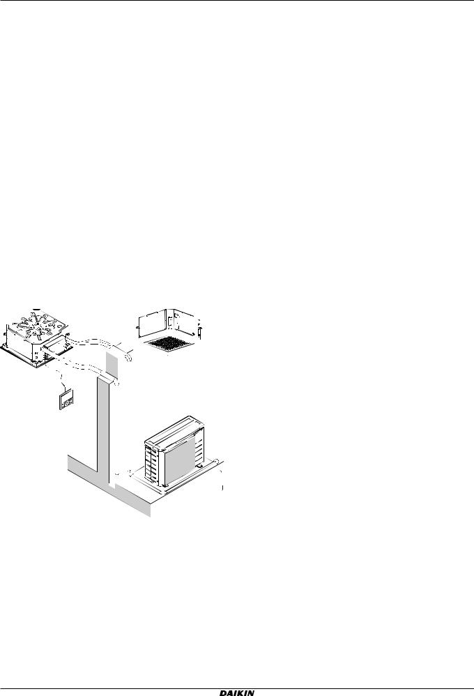
3.2System layout
|
a |
|
|
(mm) |
|
|
A |
Minimum distance to the wall |
|
|
|
|
||
|
|
|
B |
Minimum and maximum distance to the floor (see below) |
|
f |
|
C |
≥295 mm: In case of installation with BYFQ60B |
|
|
a |
≥300 mm: In case of installation with BYFQ60C |
|
|
|
|
Indoor unit |
|
|
|
|
b |
Lighting (the figure shows ceiling-mounted lighting, but |
g |
e |
i |
c |
recessed lighting is also allowed) |
Air fan |
||||
|
d |
|
d |
Static volume (example: table) |
|
▪ Minimum and maximum distance to the floor: |
|||
|
|
|||
|
b |
▪ Minimum: 2.5 m to avoid accidental touching. |
||
|
▪ |
Maximum: Depends on the air flow directions and the capacity |
||
|
|
|||
c |
class. Also make sure the "Ceiling height" field setting |
|
corresponds with the actual situation. See Field settings. |
||
|
aIndoor unit
bOutdoor unit
cUser interface
dSuction air
eDischarge air
fRefrigerant piping + interconnection cable
gDrain pipe
hEarth wiring
iSuction grille and air filter
5 Installation
h |
5.1 |
Mounting the indoor unit |
5.1.1Precautions when mounting the indoor unit
INFORMATION
Also read the precautions and requirements in the following chapters:
▪General safety precautions
▪Preparation
FFA25~60A2VEB
Split system air conditioners 4P456960-1 – 2017.03
5.1.2Guidelines when installing the indoor unit
INFORMATION
Optional equipment. When installing optional equipment, also read the installation manual of the optional equipment. Depending on the field conditions, it might be easier to install the optional equipment first.
Installation and operation manual
5
5 Installation
▪Decoration panel. Install the decoration panel always after installing the unit.
▪Ceiling strength. Check whether the ceiling is strong enough to support the weight of the unit. If there is a risk, reinforce the ceiling before installing the unit.
▪For existing ceilings, use anchors.
▪For new ceilings, use sunken inserts, sunken anchors or other field supplied parts.
|
|
|
|
|
|
|
|
|
|
|
|
a |
|
|
|
|
|
|
|
|
|
|
|
|
|
|
|
|
|
|
|
|
|
|
|
|
|
b |
|
|
|
|
|
|
|
|
|
|
|
|
|
|
|
|
|
A |
|
|
|
|
|
|
|
c |
|
|
|
|
|
|
|
|
|
|
|
||
|
|
|
|
|
|
|
|
|
|
|
d |
|
|
|
|
|
|
|
|
|
|
|
|
e |
|
|
|
|
|
|
|
|
|
|
|
|
|
|
|
|
|
|
|
|
|
|
|
|
|
|
|
|
|
|
|
|
|
|
|
|
|
|||
|
|
|
|
|
|
|
|
|
|
|
|
|
|
|
|
|
|
|
|
|
|
|
A 50~100 mm
aCeiling slab
bAnchor
cLong nut or turnbuckle
dSuspension bolt
eSuspended ceiling
▪Suspension bolts. Use M8~M10 suspension bolts for installation. Attach the hanger bracket to the suspension bolt. Fix it securely using a nut and washer from the upper and lower sides of the hanger bracket.
|
|
a1 |
|
533 |
b |
|
c |
|
|
|
b |
|
|
a2 |
533 |
(mm) |
|
a1 Nut (field supply)
a2 Double nut (field supply)
bWasher (accessories)
cHanger bracket (attached to the unit)
▪Paper pattern for installation (upper part of the packing). Use the paper pattern to determine the correct horizontal positioning. It contains the necessary dimensions and centers. You can attach the paper pattern to the unit.
a |
|
|
|
b c |
|
d |
|||||
|
|
|
|
|
|
|
|
|
|
|
|
|
|
|
|
|
|
|
|
|
|
|
|
|
|
|
|
|
|
|
|
|
|
|
|
|
|
|
|
|
|
|
|
|
|
|
|
|
|
|
|
|
|
|
|
|
|
|
|
|
|
|
|
|
|
|
|
|
|
|
|
|
|
|
|
|
|
|
|
|
|
|
|
|
|
|
|
|
|
|
|
|
|
|
|
aCentre of the unit
bCentre of the ceiling opening
cPaper pattern for installation (upper part of the packing)
dScrews (accessories)
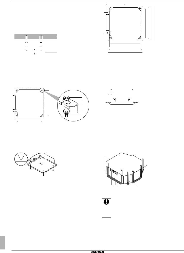
▪Ceiling opening and unit:
▪Make sure the ceiling opening is within the following limits:
Minimum: 585 mm to be able to fit the unit.
Maximum: 660 mm in case of installation with BYFQ60B and 595 mm in case of installation with BYFQ60C ensure enough overlapping between the decoration panel and the suspended ceiling. If the ceiling opening is larger, add extra ceiling material.
▪Make sure the unit and its hanger brackets (suspension) are centered within the ceiling opening.
Installation and operation manual
6
350
a
c 533 d 575 A B
b
c533
d575
A
B  (mm)
(mm)
A585~660 mm: In case of installation with BYFQ60B 585~595 mm: In case of installation with BYFQ60C
B700 mm: In case of installation with BYFQ60B
620 mm: In case of installation with BYFQ60C
aDrain piping
bRefrigerant piping
cHanger bracket pitch (suspension)
dUnit
|
|
|
|
|
|
|
|
|
|
|
|
|
|
|
|
|
|
|
|
|
|
|
Then |
|
|
|
|
|
|
|
|
|
|
|
|
|
|
|
|
|
|
|
|
|
|
|
If A |
B |
C |
|
|
|
B |
|
|
|
|
|
|
A |
|
|
|
BYFQ60B |
|
|||||||||
|
C |
|
|
|
|
|
|
|
|
|
|
|
|
|
|
|
|
|
|
585 mm |
5 mm |
57.5 mm |
||
|
|
|
|
|
|
|
|
|
|
|
|
|
|
|
|
|
|
|
|
|
|
(= min.) |
|
|
|
|
|
|
|
|
|
|
|
|
|
|
|
|
|
|
|
|
|
|
|
|
|
|
|
|
|
|
|
|
|
|
|
|
|
|
|
|
|
|
|
|
|
|
|
|
|
660 mm |
42.5 mm |
20 mm |
|
|
|
|
|
|
|
|
|
|
|
|
|
|
|
|
|
|
|
|
|
|
|||
|
|
|
|
|
|
|
|
|
|
|
|
|
|
|
|
|
|
|
|
|
|
|||
|
|
|
|
|
|
|
|
|
|
|
|
|
|
|
|
|
|
|
|
|
|
(= max.) |
|
|
|
|
|
|
|
|
|
|
|
|
|
|
|
|
|
|
|
|
|
|
|
|
|
|
|
|
|
|
|
|
|
|
|
|
|
|
|
|
|
|
|
|
|
|
|
|
|
|
BYFQ60C |
|
|
|
|
|
|
|
|
|
|
|
|
|
|
|
|
|
|
|
|
|
|
|
585 mm |
5 mm |
17.5 mm |
|
|
|
|
|
|
|
|
|
|
|
|
|
|
|
|
|
|
|
|
|
|
(= min.) |
|
|
|
|
|
|
|
|
|
|
|
|
|
|
|
|
|
|
|
|
|
|
|
|
595 mm |
10 mm |
12.5 mm |
|
|
|
|
|
|
|
|
|
|
|
|
|
|
|
|
|
|
|
|
|
|
(= max.) |
|
|
|
|
|
|
|
|
|
|
|
|
|
|
|
|
|
|
|
|
|
|
|
|
|
|
|
ACeiling opening
BDistance between the unit and the ceiling opening
COverlap between the decoration panel and the suspended ceiling
▪Level. Make sure the unit is level at all 4 corners using a level or a water-filled vinyl tube.
c
a b |
b |
aLevel
bVinyl tube
cWater level
NOTICE
Do NOT install the unit tilted. Possible consequence: If the unit is tilted against the direction of the condensate flow (the drain piping side is raised), the float switch might malfunction and cause water to drip.
5.1.3Guidelines when installing the drain piping
Make sure condensation water can be evacuated properly. This involves:
▪General guidelines
▪Connecting the drain piping to the indoor unit
FFA25~60A2VEB Split system air conditioners 4P456960-1 – 2017.03

▪ Checking for water leaks
General guidelines
▪Pipe length. Keep drain piping as short as possible.
▪Pipe size. Keep the pipe size equal to or greater than that of the
connecting pipe (vinyl pipe of 25 mm nominal diameter and 32 mm outer diameter).
▪Slope. Make sure the drain piping slopes down (at least 1/100) to prevent air from being trapped in the piping. Use hanging bars as shown.
1~1.5 m |
a |
|
a Hanging bar O Allowed
XNot allowed
▪Condensation. Take measures against condensation. Insulate the complete drain piping in the building.
▪Rising piping. If necessary to make the slope possible, you can install rising piping.
▪Drain hose inclination: 0~75 mm to avoid stress on the piping and to avoid air bubbles.
▪Rising piping: ≤300 mm from the unit, ≤630~675 mm (depending on the decoration panel used) perpendicular to the unit.
a |
b |
|
0~75 |
≤300 |
1000~1500 |
|
A |
|
B |
a b |
c d |
d |
(mm) |
A≤645 mm: In case of installation with BYFQ60B ≤630 mm: In case of installation with BYFQ60C
B205 mm: In case of installation with BYFQ60B
220 mm: In case of installation with BYFQ60C
aMetal clamp (accessory)
bDrain hose (accessory)
cRising drain piping (vinyl pipe of 25 mm nominal diameter and 32 mm outer diameter) (field supply)
dHanging bars (field supply)
▪Combining drain pipes. You can combine drain pipes. Make sure to use drain pipes and T-joints with the correct gauge for the operating capacity of the units.
≥100
a
A
(mm)
A≤645 mm: In case of installation with BYFQ60B ≤630 mm: In case of installation with BYFQ60C
a T-joint
FFA25~60A2VEB
Split system air conditioners 4P456960-1 – 2017.03
5 Installation
To connect the drain piping to the indoor unit
NOTICE
Incorrect connection of the drain hose might cause leaks, and damage the installation space and surroundings.
1Push the drain hose as far as possible over the drain pipe connection.
2Tighten the metal clamp until the screw head is less than 4 mm from the metal clamp part.
3Check for water leaks (see "To check for water leaks" on page 7).
4Install the insulation piece (drain pipe).
5Wind the large sealing pad (= insulation) around the metal clamp and drain hose, and fix it with cable ties.
6Connect the drain piping to the drain hose.
1 a |
b |
2~6 e |
|
c |
d |
f |
|
|||
|
|
|
|
4 |
2 |
|
|
5 |
|
6 |
|
|
|
|
|
|
|||||
|
|
|
|
|
|
|
|
|
|
|
1 |
A |
|
|
|
|
|
A' |
|
|
≤4 mm |
|
A-A' |
d |
3 |
c |
||
|
b |
|
|
a |
|
aDrain pipe connection (attached to the unit)
bDrain hose (accessory)
cMetal clamp (accessory)
dLarge sealing pad (accessory)
eInsulation piece (drain pipe) (accessory)
fDrain piping (field supply)
To check for water leaks
The procedure differs depending on whether electrical wiring is already finished. When electrical wiring is not finished yet, you need to temporarily connect the user interface and power supply to the unit.
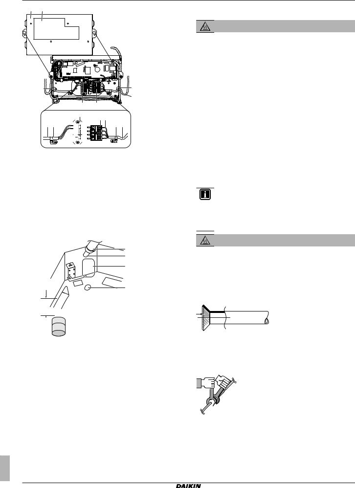
When electrical wiring is not finished yet
1Temporarily connect electrical wiring.
▪Remove the control box cover (a).
▪Connect the single-phase power supply (50 Hz, 230 V) to connections No. 1 and No. 2 on the terminal block for power supply (d) and earth (c).
▪Reattach the control box cover (a).
Installation and operation manual
7
5 Installation
a h
g |
|
|
|
|
g |
|
|
|
|
|
b |
|
|
|
f |
d |
|
|
|
|
f |
d c |
|
|
|
|
|
b |
|
i |
e |
S |
P1 |
e |
|
|
|
RC |
|
|
|
|
|
N |
P2 |
|
|
|
|
TRAN WIRI |
F1 |
|
|
|
|
F2 M G |
|
|
|
|
|
. |
T2 T1 |
|
|
|
|
OFF |
|
|
|
|
|
FORCED |
|
|
|
aControl box cover
bInter-unit wiring
cEarth cable
dTerminal block for power supply
eClamp
fTerminal board for transmission wiring
gOpening for cables
hWiring diagram label (on the back of the control box lid)
iRemote controller wiring
2Turn ON the power.
3Start cooling operation (see "7.4 To perform a test run" on page 12).
4Gradually pour approximately 1 l of water through the air discharge outlet, and check for leaks.
e |
d |
c |
b
mm≥100


 a
a
5.2Connecting the refrigerant piping
DANGER: RISK OF BURNING
5.2.1About connecting the refrigerant piping
Before connecting the refrigerant piping
Make sure the outdoor and indoor unit are mounted.
Typical workflow
Connecting the refrigerant piping involves:
▪Connecting the refrigerant piping to the outdoor unit
▪Connecting the refrigerant piping to the indoor unit
▪Insulating the refrigerant piping
▪Keeping in mind the guidelines for:
▪Pipe bending
▪Flaring pipe ends
▪Brazing
▪Using the stop valves
5.2.2Precautions when connecting the refrigerant piping
INFORMATION
Also read the precautions and requirements in the following chapters:
▪General safety precautions
▪Preparation
DANGER: RISK OF BURNING
5.2.3Guidelines when connecting the refrigerant piping
Take the following guidelines into account when connecting pipes:
▪Coat the flare inner surface with ether oil or ester oil when connecting a flare nut. Tighten 3 or 4 turns by hand, before tightening firmly.
aPlastic watering can
bService drain outlet (with rubber plug). Use this outlet to drain water from the drain pan.
cDrain pump location
dDrain pipe connection
eDrain pipe
5Turn OFF the power.
6Disconnect the electrical wiring.
▪Remove the control box cover.
▪Disconnect the power supply and earth.
▪Reattach the control box cover.
When electrical wiring is finished already
1Start cooling operation (see "7.4 To perform a test run" on page 12).
2Gradually pour approximately 1 l of water through the air discharge outlet, and check for leaks (see When electrical wiring is not finished yet).
▪Always use 2 wrenches together when loosening a flare nut.
▪Always use a spanner and torque wrench together to tighten the flare nut when connecting the piping. This to prevent nut cracking and leaks.
a 
 b
b

 c d
c d 


aTorque wrench
bSpanner
cPiping union
dFlare nut
Installation and operation manual |
FFA25~60A2VEB |
8 |
Split system air conditioners |
4P456960-1 – 2017.03 |
Loading...