


 Loading...
Daikin EWWD 120 MBYNN, EWWD 180 MBYNN, EWWD 240 MBYNN, EWWD 280 MBYNN, EWWD 360 MBYNN Operation manuals
...OPERATION MANUAL
Packaged water-cooled water chillers
EWWD120MBYNN
EWWD180MBYNN
EWWD240MBYNN
EWWD280MBYNN
EWWD360MBYNN
EWWD440MBYNN
EWWD500MBYNN
EWWD520MBYNN
EWWD540MBYNN

EWWD120MBYNN EWWD280MBYNN EWWD500MBYNN EWWD180MBYNN EWWD360MBYNN EWWD520MBYNN EWWD240MBYNN EWWD440MBYNN EWWD540MBYNN
Packaged water-cooled water chillers |
Operation manual |
CONTENTS |
Page |
Introduction ....................................................................................... |
1 |
Technical specifications ............................................................................. |
1 |
Electrical specifications ............................................................................. |
2 |
Description ........................................................................................ |
3 |
Function of the main components.............................................................. |
4 |
Safety devices............................................................................................ |
5 |
Internal wiring - Parts table........................................................................ |
5 |
Before operation................................................................................ |
6 |
Checks before initial start-up ..................................................................... |
6 |
Water supply.............................................................................................. |
7 |
Power supply connection and crankcase heating...................................... |
7 |
General recommendations ........................................................................ |
7 |
Operation .......................................................................................... |
7 |
Digital controller ......................................................................................... |
7 |
Working with the unit ................................................................................. |
8 |
Advanced features of the digital controller............................................... |
11 |
Troubleshooting ............................................................................... |
17 |
Maintenance.................................................................................... |
20 |
Maintenance activities ............................................................................. |
20 |
Disposal requirements ............................................................................. |
20 |
READ THIS MANUAL ATTENTIVELY BEFORE STARTING UP THE UNIT. DO NOT THROW IT AWAY. KEEP IT IN YOUR FILES FOR FUTURE REFERENCE.
INTRODUCTION
This operation manual concerns packaged water-cooled water chillers of the Daikin EWWD-MBYNN series. These units are provided for indoor installation and used for cooling applications. The EWWD units can be combined with Daikin fan coil units or air handling units for air conditioning purposes. They can also be used for supplying water for process cooling.
This manual has been prepared to ensure adequate operation and maintenance of the unit. It will tell you how to use the unit properly and will provide help if problems occur. The unit is equipped with safety devices, but they will not necessarily prevent all problems caused by improper operation or inadequate maintenance.
In case of persisting problems contact your local Daikin Dealer.
Before starting up the unit for the first time, make sure that it has been properly installed. It is therefore necessary to carefully read the installation manual supplied with the unit and the recommendations listed in "Checks before initial start-up" on page 6.
Technical specifications(1)
General EWWD |
|
120 |
180 |
240 |
|
Dimensions HxWxD |
(mm) |
|
1014x2672x930 |
|
|
Weight |
|
|
|
|
|
• machine weight |
(kg) |
1000 |
1273 |
1527 |
|
• operation weight |
(kg) |
1032 |
1318 |
1588 |
|
Connections |
|
|
|
|
|
• chilled water inlet |
(inch) |
3" OD |
3" (88.9 mm OD) |
||
and outlet(a) |
(76 mm OD) |
||||
• condenser water inlet |
(inch) |
2-1/2" |
3" (88.9 mm OD) |
||
and outlet(a) |
|||||
• pressure relief valve |
(inch) |
1x 1" |
1x 1" |
2x 1" |
|
condenser |
|||||
|
|
|
|
||
Compressor |
|
|
|
|
|
Type |
|
semi-hermetic single screw |
|||
Qtyxmodel |
|
1x |
1x |
1x |
|
|
ZHA5LMGUYE |
ZHA7MSGUYE |
ZHA7WSGUYE |
||
|
|
||||
Speed |
(rpm) |
|
2880 |
|
|
Oil type |
|
|
FVC 68D |
|
|
Oil charge volume |
(l) |
7.5+0–0.5 |
10+0–0.5 |
10+0–0.5 |
|
Condensor |
|
|
|
|
|
Type |
|
|
shell & tube |
|
|
Qty x model |
|
1x CDEW215 |
1x CDEW260 |
1x CDEW400 |
|
Evaporator |
|
|
|
|
|
Type |
|
brased plate heatexchanger |
|||
Qtyxmodel |
|
1x AC120EQ-NP156 1x AC250EQ-NP96 1x AC250EQ-NP128 |
|||
|
|
|
|
|
|
General EWWD |
|
280 |
360 |
440 |
|
Dimensions HxWxD |
(mm) |
1014x2672x |
2000x2672x930 |
||
|
930 |
||||
|
|
|
|
||
Weight |
|
|
|
|
|
• machine weight |
(kg) |
1623 |
2546 |
2800 |
|
• operation weight |
(kg) |
1693 |
2636 |
2906 |
|
Connections |
|
|
|
|
|
• chilled water inlet |
(inch) |
3" |
2x 3" (2x 88.9 mm OD) |
||
and outlet(a) |
(88.9 mm OD) |
||||
• condenser water inlet |
(inch) |
3" |
2x 3" (2x 88.9 mm OD) |
||
and outlet(a) |
(88.9 mm OD) |
||||
• pressure relief valve |
(inch) |
2x 1" |
2x 1" |
3x 1" |
|
condenser |
|||||
|
|
|
|
||
Compressor |
|
|
|
|
|
Type |
|
semi-hermetic single screw |
|||
Qtyxmodel |
|
1x |
2x |
1x ZHA7MSGUYE+ |
|
|
ZHA9LSGUYE |
ZHA7MSGUYE |
1x ZHA7WSGUYE |
||
|
|
||||
Speed |
(rpm) |
|
2880 |
|
|
Oil type |
|
|
FVC 68D |
|
|
Oil charge volume |
(l) |
14+0.5 |
2x 10+0.5 |
2x 10+0.5 |
|
|
|
–0 |
–0 |
–0 |
|
Condensor |
|
|
|
|
|
Type |
|
|
shell & tube |
|
|
Qtyxmodel |
|
1x CDEW450 |
2x CDEW260 |
1x CDEW400 |
|
|
1x CDEW260 |
||||
|
|
|
|
||
Evaporator |
|
|
|
|
|
Type |
|
brased plate heatexchanger |
|||
Qtyxmodel |
|
1x AC250EQ-NP162 2x AC250EQ-NP96 |
1x AC250EQ-NP96 |
||
|
|
|
|
1x AC250EQ-NP128 |
|
(a) Victaulic® coupling
|
(1) Refer to the engineering data book for the complete list of specifications. |
|
|
Operation manual |
EWWD120~540MBYNN |
1 |
Packaged water-cooled water chillers |
4PW22685-1 |

General EWWD |
|
500 |
520 |
540 |
Dimensions HxWxD |
(mm) |
|
2000x2672x930 |
|
Weight |
|
|
|
|
• machine weight |
(kg) |
3034 |
3150 |
3346 |
• operation weight |
(kg) |
3156 |
3281 |
3485 |
Connections |
|
|
|
|
• chilled water inlet |
(inch) |
2x 3" (2x 88.9 mm OD) |
||
and outlet(a) |
||||
• condenser water inlet |
(inch) |
2x 3" (2x 88.9 mm OD) |
||
and outlet(a) |
||||
• pressure relief valve |
(inch) |
|
4x 1" |
|
condenser |
|
|
||
|
|
|
|
|
Compressor |
|
|
|
|
Type |
|
semi-hermetic single screw |
||
Qtyxmodel |
|
2x |
1x ZHA7WSGUYE+ |
2x |
|
ZHA7WSGUYE |
1x ZHA9LSGUYE |
ZHA9LSGUYE |
|
|
|
|||
Speed |
(rpm) |
|
2880 |
|
Oil type |
|
|
FVC 68D |
|
Oil charge volume |
(l) |
2x 10+0–0.5 |
10+0–0.5 +14+0–0.5 |
2x 14+0–0.5 |
Condensor |
|
|
|
|
Type |
|
|
shell & tube |
|
Qtyxmodel |
|
2x CDEW400 |
1x CDEW400 |
2x CDEW450 |
|
1x CDEW450 |
|||
|
|
|
|
|
Evaporator |
|
|
|
|
Type |
|
brased plate heatexchanger |
||
Qtyxmodel |
|
2x AC250EQ-NP128 |
1x AC250EQ-NP128 |
2x AC250EQ-NP162 |
|
1x AC250EQ-NP162 |
|||
|
|
|
|
|
(a) Victaulic® coupling
Electrical specifications(1)
Model EWWD |
|
120 |
180 |
240 |
280 |
360 |
440 |
500 |
520 |
540 |
|
|
|||||||||||
Power supply |
|
|
|
|
|
|
|
|
|
|
|
• Phase |
|
|
|
|
|
|
3~ |
|
|
|
|
• Frequency |
|
(Hz) |
|
|
|
|
50 |
|
|
|
|
• Voltage |
|
(V) |
|
|
|
|
400 |
|
|
|
|
• Voltage tolerance |
|
(%) |
|
|
|
|
±10 |
|
|
|
|
Unit |
|
|
|
|
|
|
|
|
|
|
|
• Nominal running |
|
(A) |
48 |
78 |
108 |
118 |
156 |
186 |
216 |
226 |
236 |
current |
|
||||||||||
|
|
|
|
|
|
|
|
|
|
|
|
• Maximum running |
|
(A) |
76 |
120 |
174 |
184 |
240 |
294 |
348 |
358 |
368 |
current |
|
||||||||||
|
|
|
|
|
|
|
|
|
|
|
|
• Recommended fuses |
|
(gL) |
3x 100 |
3x 160 |
3x 200 |
3x 200 |
2x 3x 200 |
3x 200+3x 250 |
2x 3x 250 |
2x 3x 250 |
2x 3x 250 |
according to IEC 269-2 |
|
||||||||||
|
|
|
|
|
|
|
|
|
|
|
|
Compressor |
|
|
|
|
|
|
|
|
|
|
|
• Phase |
|
|
|
|
|
|
3~ |
|
|
|
|
• Frequency |
|
(Hz) |
|
|
|
|
50 |
|
|
|
|
• Voltage |
|
(V) |
|
|
|
|
400 |
|
|
|
|
• Nominal running current |
(A) |
48 |
78 |
108 |
118 |
78+78 |
78+108 |
108+108 |
108+118 |
118+118 |
|
Control and fan motor |
|
|
|
|
|
|
|
|
|
|
|
• Phase |
|
|
|
|
|
|
1~ |
|
|
|
|
• Frequency |
|
(Hz) |
|
|
|
|
50 |
|
|
|
|
• Voltage |
|
(V) |
|
|
|
|
230 |
|
|
|
|
|
|
|
|
|
|
|
|
|
|
|
|
(1) Refer to the engineering data book for the complete list of specifications.
EWWD120~540MBYNN |
Operation manual |
Packaged water-cooled water chillers |
2 |
4PW22685-1 |

DESCRIPTION
The EWWD water-cooled water chillers are available in 9 standard sizes.
|
300 |
|
700 |
| <![if ! IE]> <![endif]>850 |
<![if ! IE]> <![endif]>500 |
16 |
|
9 |
900 |
|
|
18 |
|
<![endif]>1000 600
|
7 |
6 |
|
|
11 8 |
|
|
9 |
|
|
|
|
3 |
|
|
|
|
22 |
4 21 20 |
23 |
|
|
|
5 |
10 |
1 |
2 |
30 28 29 |
13 |
12 |
|
|
|
|
|
|
||||||||||||||||||||||||||||
|
|
|
|
|
|
|
|
|
|
|
|
|
|
|
|
|
|
|
|
|
|
|
|
|
|
|
|
|
|
|
|
|
|
|
|
|
|
|
|
|
|
|
|
|
|
|
|
|
|
|
|
|
|
|
|
|
|
|
|
|
|
|
|
14 |
|
|
|
|
|
|
|
|
|
|
|
|
|
|
|
|
|
|
|
|
|
|
|
|
|
|
|
|
|
|
|
|
|
|
|
|
|
|
|
|
|
|
|
|
|
|
|
|
|
|
|
|
|
|
|
|
|
|
|
|
|
|
|
||
|
|
|
|
|
|
|
|
|
|
|
|
|
|
|
|
|
|
|
|
|
|
|
|
|
|
|
|
|
|
|
|
|
|
|
|
|
|
|
|
|
|
|
|
|
|
|
|
|
|
|
|
|
|
|
|
|
|
|
|
|
|
|
||
|
|
|
|
|
|
|
|
|
|
|
|
|
|
|
|
|
|
|
|
|
|
|
|
|
|
|
|
|
|
|
|
|
|
|
|
|
|
|
|
|
|
|
|
|
|
|
|
|
|
|
|
|
|
|
|
|
|
|
15 |
|||||
|
|
|
|
|
|
|
|
|
|
|
|
|
|
|
|
|
|
|
|
|
|
|
|
|
|
|
|
|
|
|
|
|
|
|
|
|
|
|
|
|
|
|
|
|
|
|
|
|
|
|
|
|
|
|
|
|
|
|
||||||
| <![if ! IE]> <![endif]>EWWD360~540 |
|
<![if ! IE]> <![endif]>EWWD120~280 |
|
|
|
|
|
|
|
|
|
|
|
|
|
|
|
|
|
|
|
|
|
|
|
|
|
|
|
|
|
|
|
|
|
|
|
|
|
|
|
|
|
|
|
|
|
|
|
|
|
|
|
|
|
|
19 |
|||||||
|
|
|
|
|
|
|
|
|
|
|
|
|
|
|
|
|
|
|
|
|
|
|
|
|
|
|
|
|
|
|
|
|
|
|
|
|
|
|
|
|
|
|
|
|
|
|
|
|
|
|
|
|
|
|
||||||||||
|
26 |
|
|
|
|
|
|
|
|
|
|
|
|
|
|
|
|
|
|
|
|
|
|
|
|
|
|
|
|
|
|
|
|
|
|
|
|
|
|
|
|
|
|
|
|
|
|
29 |
|
|
|
|
|
|
|
|
|
|
17 |
|||||
|
|
|
|
|
|
|
|
|
|
|
|
|
|
|
|
|
|
|
|
|
|
|
|
|
|
|
|
|
|
|
|
|
|
|
|
|
|
|
|
|
|
|
|
|
|
|
|
|
|
|
|
|
|
|
||||||||||
|
|
|
|
|
|
|
|
|
|
|
|
|
|
|
|
|
|
|
|
|
|
|
|
|
|
|
|
|
|
|
|
|
|
|
|
|
|
|
|
|
|
|
|
|
|
|
|
|
|
|
|
|
|
|
|
|
|
|
||||||
|
|
|
|
|
|
|
|
|
|
|
|
|
|
|
|
|
|
|
|
|
|
|
|
|
|
|
|
|
|
|
|
|
|
|
|
|
|
|
|
|
|
|
|
|
|
|
|
|
|
|
|
|
|
|
|
|
|
|
|
|
|
|
|
14 |
|
|
|
|
|
|
|
|
|
|
|
|
|
|
|
|
|
|
|
|
|
|
|
|
|
|
|
|
|
|
|
|
|
|
|
|
|
|
|
|
|
|
|
|
|
|
|
|
|
|
|
|
|
|
|
|
|
|
|
|
|
|
|
|
|
|
|
|
|
|
|
|
|
|
|
|
|
|
|
|
|
|
|
|
|
|
|
|
|
|
|
|
|
|
|
|
|
|
|
|
|
|
|
|
|
|
|
|
|
|
|
|
|
|
|
|
|
|
|
|
|
|
|
|
|
|
|
|
||
|
|
|
|
|
|
|
|
|
|
|
|
|
|
|
|
|
|
|
|
|
|
|
|
|
|
|
|
|
|
|
|
|
|
|
|
|
|
|
|
|
|
|
|
|
|
|
|
|
|
|
|
|
|
|
|
|
|
|
|
|
15 |
|||
|
|
|
|
|
|
|
|
|
|
|
|
|
|
|
|
|
|
|
|
|
|
|
|
|
|
|
|
|
|
|
|
|
|
|
|
|
|
|
|
|
|
|
|
|
|
|
|
30 28 29 |
|
|
|
|
|
19 |
||||||||||
|
|
|
|
|
|
|
|
|
|
|
|
|
|
|
|
|
|
|
|
|
|
|
|
|
|
|
|
|
|
|
|
|
|
|
|
|
|
|
|
|
|
|
|
|
|
|
|
|
|
|
|
|
|
|
|
|
|
|
|
|
|
|
|
|
|
|
|
|
|
|
|
|
|
|
|
|
|
|
|
|
|
|
|
|
|
|
|
|
|
|
|
|
|
|
|
|
|
|
|
|
|
|
|
|
|
|
|
|
|
|
|
|
|
|
|
|
|
|
|
|
|
|
|
|
|
|
|
|
|
|
|
|
|
|
|
|
|
|
|
|
|
|
|
|
|
|
|
|
|
|
|
|
|
|
|
|
|
|
|
|
|
|
|
|
|
|
|
|
|
|
|
|
|
|
|
|
|
|
|
|
|
|
|
|
|
|
|
|
|
|
|
|
|
|
|
|
|
|
|
|
|
|
|
|
|
|
|
|
|
|
|
|
|
|
|
|
|
|
|
|
|
|
|
|
|
|
|
|
|
|
|
|
|
|
|
|
|
|
|
|
|
|
|
|
|
|
|
|
|
|
|
|
|
|
|
|
|
|
|
|
|
|
|
|
|
|
|
|
|
|
|
|
|
|
|
|
|
|
|
|
|
|
|
|
|
|
|
|
|
|
|
|
|
|
|
|
|
|
|
|
|
|
|
|
|
|
|
|
|
|
|
|
|
|
|
|
|
|
|
|
|
|
|
|
|
6 |
7 |
26 |
11 8 24 |
|
|
9 |
3 |
24 |
22 |
27 |
4 |
|
|
23 |
|
25 |
5 |
10 |
1 |
2 |
29 |
|
|
|
12 |
13 |
17 |
|
|
|
|
||||||||||||||||||||||||||||||||
Figure - Main components |
|
|
|
|
|
|
|
|
|
|
|
|
|
|
|
|
|
|
|
|
|
|
|
|
|
|
|
|
|
|
|
|
|
|
|
|
|
|
|
|
|
|
|
|
|
|||||||||||||||||||
|
1 |
|
|
Compressor |
|
|
|
|
|
|
|
|
|
|
|
|
|
|
|
|
|
|
17 |
|
Leaving water temperature sensor |
|
|
|
|
|
|
|
|
|
|
|
||||||||||||||||||||||||||||
|
2 |
|
|
Evaporator |
|
|
|
|
|
|
|
|
|
|
|
|
|
|
|
|
|
|
|
|
|
|
|
|
18 |
|
Discharge stopvalve |
|
|
|
|
|
|
|
|
|
|
|
|
|
|
|
|
|
|
|
||||||||||||||
|
3 |
|
|
Condenser |
|
|
|
|
|
|
|
|
|
|
|
|
|
|
|
|
|
|
|
|
|
|
|
|
19 |
|
Condensor entering water temperature sensor |
|
|
|
|
|
|
|
|
|
||||||||||||||||||||||||
|
4 |
|
|
Switchbox |
|
|
|
|
|
|
|
|
|
|
|
|
|
|
|
|
|
|
|
|
|
|
|
|
20 |
|
Digital display controller |
|
|
|
|
|
|
|
|
|
|
|
|
|
|
|
|
|
|
|
||||||||||||||
|
5 |
|
|
Compressor switchbox |
|
|
|
|
|
|
|
|
|
|
|
|
21 |
|
Emergency stop |
|
|
|
|
|
|
|
|
|
|
|
|
|
|
|
|
|
|
|
||||||||||||||||||||||||||
|
6 |
|
|
Air purge condenser |
|
|
|
|
|
|
|
|
|
|
|
|
|
|
22 |
|
Power supply intake |
|
|
|
|
|
|
|
|
|
|
|
|
|
|
|
|
|
|
|
||||||||||||||||||||||||
|
7 |
|
|
Water drain condenser |
|
|
|
|
|
|
|
|
|
|
|
|
23 |
|
Field wiring intake |
|
|
|
|
|
|
|
|
|
|
|
|
|
|
|
|
|
|
|
||||||||||||||||||||||||||
|
8 |
|
|
Charge valve |
|
|
|
|
|
|
|
|
|
|
|
|
|
|
|
|
|
|
24 |
|
Holes for lifting |
|
|
|
|
|
|
|
|
|
|
|
|
|
|
|
|
|
|
|
||||||||||||||||||||
|
9 |
|
|
Safety valve |
|
|
|
|
|
|
|
|
|
|
|
|
|
|
|
|
|
|
25 |
|
Transportbeam |
|
|
|
|
|
|
|
|
|
|
|
|
|
|
|
|
|
|
|
||||||||||||||||||||
|
10 |
|
High pressure switch |
|
|
|
|
|
|
|
|
|
|
|
|
|
|
26 |
|
Ballvalve liquid pipe |
|
|
|
|
|
|
|
|
|
|
|
|
|
|
|
|
|
|
|
|||||||||||||||||||||||||
|
11 |
|
Drier |
|
|
|
|
|
|
|
|
|
|
|
|
|
|
|
|
|
|
|
|
|
|
|
|
|
|
27 |
|
Main isolator switch (optional) |
|
|
|
|
|
|
|
|
|
|
|
|
|
|
|
|
|
|||||||||||||||
|
12 |
|
Chilled water in (Victaulic® coupling) |
|
|
|
|
|
|
|
|
28 |
|
Filter |
|
|
|
|
|
|
|
|
|
|
|
|
|
|
|
|
|
|
|
|
|
|
|
|
||||||||||||||||||||||||||
|
13 |
|
Chilled water out (Victaulic® coupling) |
|
|
|
|
|
|
|
|
29 |
|
Counterpipe for welding |
|
|
|
|
|
|
|
|
|
|
|
|
|
|
|
|
|
|
|
|||||||||||||||||||||||||||||||
|
14 |
|
Condenser water out |
|
|
|
|
|
|
|
|
|
|
|
|
|
|
30 |
|
Flowswitch |
|
|
|
|
|
|
|
|
|
|
|
|
|
|
|
|
|
|
|
|
|
|||||||||||||||||||||||
|
15 |
|
Condenser water in |
|
|
|
|
|
|
|
|
|
|
|
|
|
|
|
|
|
|
|
|
|
|
|
|
|
|
|
|
|
|
|
|
|
|
|
|
|
|
|
|
|
|
|
|
|
||||||||||||||||
|
16 |
|
Entering water temperature sensor |
|
|
|
|
|
|
|
|
|
|
|
|
|
|
Required space around the unit for service |
|
|
|
|
|
|
|
|
|
|
|
|||||||||||||||||||||||||||||||||||
|
|
|
|
|
|
|
|
|
|
|
|
|
|
|
|
|
|
|
|
|
|
|
|
|
|
|
||||||||||||||||||||||||||||||||||||||
Operation manual |
EWWD120~540MBYNN |
3 |
Packaged water-cooled water chillers |
4PW22685-1 |

Function of the main components |
|
|
|
|
|
|
|
|
|
|
|||
A |
B1P |
B |
B3P |
C |
B1P |
D |
B4P |
E |
B6P |
F |
H |
|
|
|
13 |
|
13 |
|
13 |
|
13 |
|
13 |
|
|
|
|
|
|
R9T |
|
|
|
|
|
|
|
R10T |
|
|
|
|
|
|
|
|
|
|
|
|
|
11 |
11 |
11 |
|
|
|
|
|
|
|
|
|
|
|
G |
J |
|
|
|
12 |
|
14 |
|
12 |
|
12 |
|
14 |
11 |
11 |
11 |
|
|
Y11S |
|
|
|
|
|
|
|
|
|
|
Y21S |
|
S1PH |
S14PH |
|
|
|
|
|
|
|
|
|
|
S2PH |
S15PH |
|
|
|
M1C |
|
|
|
|
|
|
|
M2C |
|
|
|
|
|
|
|
15 |
16 |
|
|
|
|
|
|
|
|
Y15S |
|
|
(*) |
|
R3T |
|
|
|
(*) |
|
Y25S |
|
|
|
|
|
|
|
|
|
|
|
|
|||
|
|
|
|
|
|
|
|
|
|
|
|
||
6 |
9 |
5 |
|
|
|
|
4 |
4 |
|
|
|
|
|
|
|
|
|
|
|
|
|
|
|
|
|||
B2P |
|
Y16S |
|
|
|
|
|
|
|
|
Y26S |
|
B5P |
|
|
|
|
|
|
|
|
|
|
|
|
||
|
|
|
|
|
|
|
3 |
3 |
|
|
|
|
|
|
|
|
|
|
|
R4T |
|
|
R6T |
|
|
|
|
|
7 |
8 |
10 |
2 |
1 |
|
|
|
|
|
|
|
|
|
|
|
|
|
|
R5T |
|
|
|
|
|
|
|
S3T |
|
|
|
|
|
|
|
|
|
|
|
|
S4T |
|
|
|
|
|
(**) |
|
|
|
|
(***) |
|
|
|
|
|
EWWD120~280 |
|
|
|
|
|
|
|
|
|
|
|
|
|
|
|
|
|
|
EWWD360~540 |
|
|
|
|
|
|
Figure - Functional diagram
1 |
Evaporator |
12 |
Expansion valve |
(*) |
See A~E |
2 |
Condenser |
13 |
Suction stop valve (option) |
(**) |
- Standard |
3 |
Water out |
14 |
Electronic expansion valve |
|
(see F and G) only for EWWD120~180,360 |
|
- Dual pressure relief valve (OP03) |
||||
4 |
Water in |
15 |
Flowswitch |
|
|
|
(see H and J) only for EWWD240~280) |
||||
|
|
|
|
|
|
5 |
Drier |
16 |
Filter |
|
|
6 |
Discharge stop valve |
|
|
(***) |
- Standard |
7 |
Charge valve |
A |
only for EWWD120~180 |
|
(see F and G) only for EWWD360 and 440 |
|
- Dual pressure relief valve (OP03) |
||||
8 |
Stop valve |
B |
only for EWWD240~280, EWWD440~540 |
|
|
|
(see H and J) only for EWWD500~540) |
||||
|
|
|
|
|
|
9 |
Strainer |
C |
only for EWWD360 |
|
|
10 |
Sightglass |
D |
only for EWWD440 |
|
|
11 |
Safety valve |
E |
only for EWWD500~540 |
|
|
As the refrigerant circulates through the unit, changes in its state or condition occur. These changes are caused by the following main components:
■Compressor
The compressor (M*C) acts as a pump and circulates the refrigerant in the refrigeration circuit. It compresses the refrigerant vapour coming from the evaporator at the pressure at which it can easily be liquefied in the condenser.
■Condenser
The function of the condenser is to change the state of the refrigerant from gaseous to liquid. The heat gained by the gas in the evaporator is discharged through the condenser to the ambient air, and the vapour condenses to liquid.
■Filter / drier
The filter installed behind the condenser removes small particles from the refrigerant to prevent blockage of the tubes.
The drier takes water out of the system.
■Expansion valve
The liquid refrigerant coming from the condenser enters the evaporator via an expansion valve. The expansion valve brings the liquid refrigerant to a pressure at which it can easily be evaporated in the evaporator.
■Evaporator
The main function of the evaporator is to take heat from the water that flows through it. This is done by turning the liquid refrigerant, coming from the condenser, into gaseous refrigerant.
■Water in/outlet connection
The water inlet and outlet connection allow an easy connection of the unit to the water circuit of the air handling unit or industrial equipment.
■Flowswitch
The flowswitch protects the evaporator of the unit against freezing when there is no waterflow or when the waterflow is too low.
■Waterfilter
The waterfilter protects the evaporator against clogging.
EWWD120~540MBYNN |
Operation manual |
Packaged water-cooled water chillers |
4 |
4PW22685-1 |

Safety devices
The unit is equipped with three kinds of safety devices:
1General safety devices
General safety devices shut down all circuits and stop the whole unit. For this reason the unit has to be manually put on again after a general safety occurred.
2Circuit safety devices
Circuit safety devices shut down the circuit they protect. For this reason the unit does not need to be manually put on again after a circuit safety occurred.
3Part safety devices
Part safety devices shut down the part they protect.
An overview of all safety devices is given below.
■Overcurrent relay
The overcurrent relays (K*S) are located in the switchbox of the unit and protect the compressor motors in case of overload, phase failure or too low voltage. The relays are factory-set and may not be adjusted. When activated, they must be reset manually, followed by a reset of the controller.
■Compressor thermal protectors
The compressor motors are equipped with thermal protectors (Q*M). The protectors are activated when the compressor motor temperature becomes too high.
When temperature returns to normal, the protectors reset automatically, but the controller needs to be reset manually.
■Flowswitch
The unit is protected by a flowswitch (S8L).
When the water flow becomes lower than the minimum allowed water flow, the flowswitch shuts down the unit. When the water flow becomes normal, the protection resets automatically but the controller still needs to be reset manually.
■Discharge thermal protectors
The unit is equipped with discharge thermal protectors (S*T). The protectors are activated when the temperature of the refrigerant leaving the compressor becomes too high. When the temperature returns to normal the protector resets automatically and the controller needs to be reset manually.
■Freeze-up protection
The freeze-up protection prevents the water in the evaporator from freezing during operation. When the outlet water temperature is too low, the controller shuts down the circuit. When the outlet water temperature returns to normal, the unit can start up again.
When freeze-up protection occurs several times in a certain period, the freeze-up alarm will be activated and the unit will be shut down. The cause of freezing up should be investigated and after outlet water temperature has risen enough, the alarm indicator on the controller needs to be reset manually.
■Low pressure safety
When the suction pressure of a circuit is too low, the circuit controller shuts down the circuit. When the pressure returns to normal, the safety device can be reset on the controller.
■Pressure relief safety valve
The safety valve is activated when the pressure in the refrigerant circuit becomes too high. If this occurs, shut down the unit and contact your local dealer.
■High pressure switch
Each circuit is protected by two high pressure switches (S*PH) which measure the condenser pressure (pressure at the outlet of the compressor). They are installed in the compressor housing of the circuit. When the pressure becomes too high, the pressure switches are activated and the circuit stops.
The switches are factory-set and may not be adjusted. When activated, they must be reset by means of a screwdriver. The controller still needs to be reset.
■Reverse phase protector
The reverse phase protectors (R*P) prevent the screw compressors from running in the wrong direction. If the compressors do not start, two phases of the power supply must be inverted.
Internal wiring - Parts table
Refer to the internal wiring diagram supplied with the unit. The abbreviations used are listed below:
A1,A2.......... |
** ....... |
Current transfo circuit 1, circuit 2 |
A1P........................ |
|
PCB-controller |
A2P,A3P................. |
|
PCB-EEV driver circuit 1, circuit 2 |
A11P...................... |
|
Expansion board controller |
|
|
(only for EWWD360~540) |
B1P,B4P................. |
|
Low pressure transmitter for circuit 1, circuit 2 |
B2P,B5P................. |
|
High pressure transmitter for circuit 1, circuit 2 |
B3P,B6P................. |
|
Low pressure transmitter EEV for circuit 1 (A2P), |
|
|
circuit 2 (A3P) |
C11,C21 ................ |
|
Capacitor for capacity control |
|
|
(only for EWWD360~540) |
E1HC,E2HC |
.......... |
Crankcase heater compressor circuit 1, circuit 2 |
F1R,F2R ................ |
|
Fuses for reverse phase protector circuit 1, |
|
|
circuit 2 |
F1U~F3U.... |
# ........ |
Main fuses |
F6B,F11B .............. |
|
Fuse for primary of TR1 |
F7B ........................ |
|
Fuse for secondary of TR1 |
F8B ........................ |
|
Fuse for EEV driver |
F8U........................ |
|
Surge proof fuse for A1P |
F9B ........................ |
|
Surge proof fuse for secondary of TR2 |
F10B,F14B ............ |
|
Autofuse for secondary of TR2 |
F10S,F11S ............ |
|
Circuit breakers with fuses for circuit 1, circuit 2 |
|
|
(only for EWWD360~540) |
F11U~F13U........... |
|
Main fuses (only for EWWD360~540) |
F21U~F23U........... |
|
Main fuses (only for EWWD360~540) |
H1P............. |
*......... |
Indication lamp general operation |
H2P............. |
*......... |
Indication lamp alarm |
H3P............. |
*......... |
Indication lamp operation compressor 1 |
H4P............. |
*......... |
Indication lamp operation compressor 2 |
|
|
(only for EWWD360~540) |
H4P,H5P ..... |
*......... |
Changeable output (only for EWWD120~280) |
H5P,H6P ..... |
*......... |
Changeable output (only for EWWD360~540) |
J1........................... |
|
Power supply |
J2,J3,J6,J20 |
.......... |
Analog input |
J4........................... |
|
Analog output |
J5,J7,J8,J19 |
.......... |
Digital input |
J11......................... |
|
RS485 connection |
J12~J18,J21,J22 ... |
Digital output |
|
K1A,K4A ................ |
|
Auxiliary relay for safeties circuit 1, circuit 2 |
K1M,K4M............... |
|
Linecontactor for circuit 1, circuit 2 |
K2A,K5A ................ |
|
Auxiliary relay compressor thermal protector |
|
|
circuit 1, circuit 2 |
K2M,K5M............... |
|
Deltacontactor for circuit 1, circuit 2 |
K3A,K6A ................ |
|
Auxiliary relay for discharge thermal protector |
|
|
circuit 1, circuit 2 |
K3M,K6M............... |
|
Starcontactor for circuit 1, circuit 2 |
K7A,K8A ................ |
|
Auxiliary relay for high pressure circuit 1, circuit 2 |
K17S,K18S ............ |
|
Overcurrent relay for circuit 1, circuit 2 |
L1,L2,L3................. |
|
Main supply terminals |
M1C,M2C .............. |
|
Compressor motor circuit 1, circuit 2 |
Operation manual |
EWWD120~540MBYNN |
5 |
Packaged water-cooled water chillers |
4PW22685-1 |

M1S,M2S............... |
|
Stepless capacity control for compressor |
||
|
|
circuit 1, circuit 2 |
|
|
PE.......................... |
|
Main earth terminal |
|
|
Q1M,Q2M .............. |
|
Thermal protector compressor motor |
||
R1,R2 .................... |
|
Auxiliary resistance for feedback |
||
R1F,R2F................. |
|
Feedback resistance for compressor circuit 1, |
||
|
|
circuit 2 |
|
|
R1P,R2P ................ |
|
Reverse phase protector |
|
|
R3T........................ |
|
Sensor for evaporator inlet water temperature |
||
R4T,R6T ................ |
|
Sensor for evaporator outlet water temperature |
||
|
|
circuit 1, circuit 2 |
|
|
R5T........................ |
|
Sensor for condensor inlet water temperature |
||
R7T........................ |
|
Mixed outlet water temperature sensor (only for |
||
|
|
EWWD360~540) |
|
|
R8T........................ |
|
Sensor for evaporator outlet water in a DICN |
||
|
|
system |
|
|
R9T,R10T .............. |
|
Temperature sensor EEV for circuit 1 (A2P), |
||
|
|
circuit 2 (A3P) |
|
|
S1PH,S2PH........... |
|
High pressure switch circuit 1, circuit 2 |
||
S3T,S4T................. |
|
Discharge thermal protector circuit 1, circuit 2 |
||
S5E........................ |
|
Emergency stop push button |
||
S6S............. |
*......... |
Changeable switch for remote function |
||
|
|
(e.g. remote start/stop) |
|
|
S8L,S10L............... |
|
Flowswicth circuit 1, circuit 2 |
||
S9L,S11L.... |
# ........ |
Contact that closes if the pump is working |
||
S10S........... |
*......... |
Changeable switch for remote function |
||
|
|
(e.g. dual setpoint) |
|
|
S11S........... |
*......... |
Changeable switch for remote function |
||
|
|
(e.g. enable/disable capacity limitation 1) |
||
S12S........... |
*......... |
Changeable switch for remote function |
||
|
|
(e.g. enable/disable capacity limitation 2) |
||
S13S........... |
## ...... |
Main isolator switch |
|
|
S14PH,S15PH....... |
High pressure switch |
|
||
TC01,TC02 ............ |
|
Optocoupler (analog to digital signal) (only for |
||
|
|
EWWD360~540) |
|
|
TR1........................ |
|
Transfo control circuit |
|
|
TR2........................ |
|
Transfo supply controller + digital inputs |
||
V1 ............... |
** ....... |
V-meter |
|
|
V1F ........................ |
|
Filter for EEV |
|
|
V2C~V5C .............. |
|
Ferrite for EEV |
|
|
X2A~X4A............... |
|
Connector 24, 20, 16 pole to main switchbox |
||
|
|
(only for EWWD360~540) |
|
|
Y1E,Y2E ................ |
|
Electronic expantion valve circuit 1, circuit 2 |
||
Y11S,Y21S ............ |
|
12% capacity step for compressor circuit 1, |
||
|
|
circuit 2 |
|
|
Y15S,Y25S ............ |
|
Liquid injection valve of the compressor circuit 1, |
||
|
|
circuit 2 |
|
|
Y16S,Y26S ............ |
|
Liquid line solenoid valve circuit 1, circuit 2 |
||
|
|
|
|
|
|
|
Not included with standard unit |
||
|
|
|
|
|
|
|
Not possible as option |
|
Possible as option |
|
|
|
|
|
Obligatory |
# |
|
## |
|
|
|
|
|
|
Not obligatory |
* |
|
** |
|
|
|
|
|
|
BEFORE OPERATION
Checks before initial start-up
Make sure that the circuit breaker on the power supply panel of the unit is switched off.
After the installation of the unit, check the following before switching on the circuit breaker:
1Field wiring
Make sure that the field wiring between the local supply panel and the unit has been carried out according to the instructions described in the installation manual, according to the wiring diagrams and according to European and national regulations.
2Additional pump interlock contact
Additional pump interlock contact (S9L) must be provided. Make sure that the contact has been installed between the appropriate terminals (refer to the wiring diagram supplied with the unit). The contact must be a normal open contact.
3Fuses or protection devices
Check that the fuses or the locally installed protection devices are of the size and type specified in the installation manual. Make sure that neither a fuse nor a protection device has been bypassed.
4Earth wiring
Make sure that the earth wires have been connected properly and that the earth terminals are tightened.
5Internal wiring
Visually check the switch box on loose connections or damaged electrical components.
6Fixation
Check that the unit is properly fixed, to avoid abnormal noises and vibrations when starting up the unit.
7Damaged equipment
Check the inside of the unit on damaged components or squeezed pipes.
8Refrigerant leak
Check the inside of the unit on refrigerant leakage. If there is a refrigerant leak, call your local dealer.
9Oil leak
Check the compressor on oil leakage. If there is an oil leak, call your local dealer.
10Stop valves
Open the liquid line, discharge and suction (if provided) stopvalves completely.
11Power supply voltage
Check the power supply voltage on the local supply panel. The voltage must correspond to the voltage on the identification label of the unit.
12Water connection
Check water piping system and circulating pumps.
Check if the filter kit that was supplied with the unit separately is installed correctly in front of the evaporator water inlet.
13Water sensors
Check that all the water sensors are correctly fixed into the pipes connected to the evaporator.
EWWD120~540MBYNN |
Operation manual |
Packaged water-cooled water chillers |
6 |
4PW22685-1 |
Water supply
Fill the water piping, taking into account the minimum water volume required by the unit. Refer to the "installation manual".
Make sure that the water is of the quality as mentioned in the installation manual.
Purge the air at the high points of the system and check the operation of the circulation pump and the flowswitch.
Power supply connection and crankcase heating
In order to avoid compressor damage, it is necessary to switch on the crankcase heater for at least 8 hours before starting the compressor after a long period of standstill.
To switch on the crankcase heater proceed as follows:
1Switch on the circuit breaker on the local supply panel. Make sure that the unit is "OFF".
2The crankcase heater is switched on automatically.
3Check the supply voltage on the supply terminals L1, L2, L3, by means of a voltmeter. The voltage must correspond to the voltage indicated on the identification label of the unit. If the voltmeter reads values which are not within the ranges specified in the technical data, check the field wiring and replace the supply cables if necessary.
4Check the LED on the reverse phase protectors. If it lights up, the phase order is correct. If not, switch off the circuit breaker and call a licensed electrician to connect the wires of the power supply cable in the correct phase order.
5Check if the crankcaseheaters are warming up.
After 8 hours, the unit is ready for operation.
General recommendations
Before switching on the unit, read following recommendations:
1When the complete installation and all necessary settings have been carried out, close all front panels of the unit.
2The service panels of the switch boxes may only be opened by a licensed electrician for maintenance purposes.
3To prevent the evaporator from freezing and to avoid damage to the LCD displays of the digital controller, never switch off the power supply during winter.
Legibility of the alphanumeric display may decrease at low temperatures.
OPERATION
The EWWD120~540 units are equipped with a digital controller offering a user-friendly way to set up, use and maintain the unit.
This part of the manual has a task-oriented, modular structure. Apart from the first section, which gives a brief description of the controller itself, each section or subsection deals with a specific task you can perform with the unit.
Depending on the model there are one or two cooling circuits in the system. The models EWWD360~540 exist out of two circuits, whereas the models EWWD120~280 only have one circuit. These circuits are generally named C1 and C2 in the following descriptions. So all information about circuit 2 ( ) is not applicable for EWWD120~280 models.
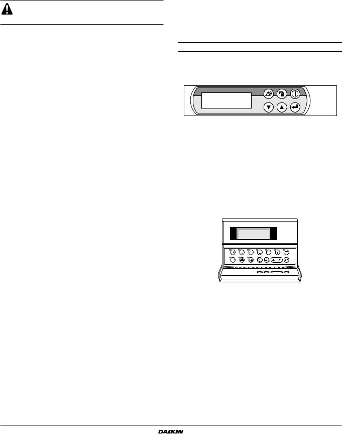
Digital controller
User interface
The digital controller consists of an alphanumeric display, labelled keys which you can press and a number of LEDs.
■Digital built-in controller
Figure - Digital built-in controller
Keys:
fkey, to enter the main menu
okey, to start up or to shut down the unit.
pkey, to enter the safeties menu or to reset an alarm.
g |
keys, to scroll up or down through the screens of a menu |
|
(only in case W, X or C appears) or to raise, respectively |
||
h |
||
lower a setting. |
||
|
qkey, to confirm a selection or a setting.
■Digital remote controller (to be ordered separately)
Figure - Digital controller
okey, to start up or to shut down the unit.
pkey, to enter the safeties menu or to reset an alarm.
kkey, to scroll through the screens of a menu (only in case W, X or C appears) or to raise, respectively lower a setting.
qkey, to confirm a selection or a setting.
ukey, to enter the readout menu.
skey, to enter the setpoints menu.
zkey, to enter the user settings menu.
ekey, to enter the timers menu.
rkey, to enter the history menu.
tkey, to enter the info menu.
ykey, to enter the input/output status menu.
Operation manual |
EWWD120~540MBYNN |
7 |
Packaged water-cooled water chillers |
4PW22685-1 |
Loading...