


Daikin ERHQ011BA, ERHQ014BA, ERHQ016BA, ERLQ011CA, ERLQ014CA Installer reference guide
...INSTALLER
REFERENCE GUIDE
Daikin Altherma - Low Temperature Split
+
ERHQ011BA
ERHQ014BA
ERHQ016BA
ERLQ011CA
ERLQ014CA
ERLQ016CA
EHVH16S18CA
EHVH16S26CA
EHVX16S18CA
EHVX16S26CA

Table of contents |
|
7 |
Installation |
22 |
||||||
|
|
|
|
|
|
7.1 |
Opening the units........................................................................... |
22 |
||
1 |
About the documentation |
2 |
|
|
7.1.1 |
To open the indoor unit and switch box cover .................... |
22 |
|||
|
7.2 Mounting the indoor unit ................................................................ |
23 |
||||||||
|
1.1 |
About this document |
2 |
|
|
7.2.1 |
To install the indoor unit ..................................................... |
23 |
||
|
|
7.3 Connecting the water piping |
23 |
|||||||
2 |
General safety precautions |
2 |
|
|||||||
|
|
7.3.1 |
To connect the water piping ............................................... |
23 |
||||||
|
2.1 |
About the documentation ................................................................. |
2 |
|
|
7.3.2 |
To connect the pressure relief valve to the drain................ |
23 |
||
|
|
2.1.1 Meaning of warnings and symbols ....................................... |
2 |
|
|
7.3.3 |
To fill the water circuit......................................................... |
24 |
||
|
2.2 |
For the installer ................................................................................ |
3 |
|
|
7.3.4 |
To fill the domestic hot water tank ...................................... |
24 |
||
|
|
2.2.1 |
General................................................................................. |
3 |
|
|
7.3.5 |
To insulate the water piping................................................ |
24 |
|
|
|
2.2.2 |
Installation site...................................................................... |
3 |
|
7.4 Connecting the electrical wiring ..................................................... |
24 |
|||
|
|
2.2.3 |
Refrigerant............................................................................ |
3 |
|
|
7.4.1 |
About electrical compliance ............................................... |
24 |
|
|
|
2.2.4 |
Water.................................................................................... |
3 |
|
|
7.4.2 |
To connect the electrical wiring on the indoor unit ............. |
25 |
|
|
|
2.2.5 |
Electrical............................................................................... |
4 |
|
|
7.4.3 |
To connect the main power supply..................................... |
25 |
|
3 |
About the box |
4 |
|
|
7.4.4 |
To connect the backup heater power supply...................... |
26 |
|||
|
|
7.4.5 |
To connect the user interface |
27 |
||||||
|
3.1 |
Indoor unit |
4 |
|
|
|||||
|
|
|
7.4.6 |
To connect the shut-off valve |
28 |
|||||
|
|
3.1.1 To unpack the indoor unit |
4 |
|
|
|||||
|
|
|
|
7.4.7 |
To connect the electrical meters |
29 |
||||
|
|
3.1.2 To remove the accessories from the indoor unit |
4 |
|
|
|||||
|
|
|
|
7.4.8 |
To connect the domestic hot water pump |
29 |
||||
4 About the units and options |
5 |
|
|
|||||||
|
|
7.4.9 |
To connect the alarm output............................................... |
29 |
||||||
|
4.1 |
Identification..................................................................................... |
5 |
|
|
7.4.10 |
To connect the space cooling/heating ON/OFF output ...... |
29 |
||
|
|
4.1.1 Identification label: Indoor unit.............................................. |
5 |
|
|
7.4.11 |
To connect the changeover to external heat source .......... |
29 |
||
|
4.2 Possible combinations of units and options ..................................... |
5 |
|
|
7.4.12 To connect the power consumption digital inputs............... |
29 |
||||
|
|
4.2.1 List of options for indoor unit ................................................ |
5 |
|
7.5 Finishing the indoor unit installation............................................... |
30 |
||||
|
|
4.2.2 Possible combinations of indoor unit and outdoor unit......... |
6 |
|
|
7.5.1 |
To fix the user interface cover to the indoor unit ................ |
30 |
||
5 |
Application guidelines |
6 |
|
|
7.5.2 |
To close the indoor unit ...................................................... |
30 |
|||
8 |
Configuration |
30 |
||||||||
|
5.1 |
Overview: Application guidelines ..................................................... |
6 |
|||||||
|
5.2 Setting up the space heating/cooling system................................... |
6 |
|
8.1 |
Overview: Configuration ................................................................ |
30 |
||||
|
|
5.2.1 |
Single room .......................................................................... |
7 |
|
|
8.1.1 |
To connect the PC cable to the switch box ........................ |
30 |
|
|
|
5.2.2 Multiple rooms – One LWT zone .......................................... |
8 |
|
|
8.1.2 |
To access the most used commands ................................. |
30 |
||
|
|
5.2.3 Multiple rooms – Two LWT zones ...................................... |
10 |
|
|
8.1.3 |
To copy the system settings from the first to the second user |
|||
|
5.3 Setting up an auxiliary heat source for space heating ................... |
11 |
|
|
|
interface ............................................................................. |
31 |
|||
|
5.4 Setting up the domestic hot water tank .......................................... |
12 |
|
|
8.1.4 |
To copy the language set from the first to the second user |
||||
|
|
5.4.1 System layout – Integrated DHW tank ............................... |
12 |
|
|
|
interface ............................................................................. |
31 |
||
|
|
5.4.2 System layout – Standalone DHW tank ............................. |
13 |
|
|
8.1.5 |
Quick wizard: Set the system layout after first |
|
||
|
|
5.4.3 Selecting the volume and desired temperature for the DHW |
|
|
|
power ON ........................................................................... |
31 |
|||
|
|
|
tank..................................................................................... |
13 |
|
8.2 |
Basic configuration ........................................................................ |
32 |
||
|
|
5.4.4 Setup and configuration – DHW tank ................................. |
13 |
|
|
8.2.1 |
Quick wizard: Language / time and date............................ |
32 |
||
|
|
5.4.5 Combination: Standalone DHW tank + Solar panels.......... |
14 |
|
|
8.2.2 |
Quick wizard: Standard ...................................................... |
32 |
||
|
|
5.4.6 DHW pump for instant hot water ........................................ |
14 |
|
|
8.2.3 |
Quick wizard: Options ........................................................ |
34 |
||
|
|
5.4.7 DHW pump for disinfection................................................. |
14 |
|
|
8.2.4 |
Quick wizard: Capacities (energy metering) ...................... |
35 |
||
|
5.5 Setting up the energy metering...................................................... |
14 |
|
|
8.2.5 |
Space heating/cooling control ............................................ |
36 |
|||
|
|
5.5.1 |
Produced heat .................................................................... |
14 |
|
|
8.2.6 |
Domestic hot water control................................................. |
39 |
|
|
|
5.5.2 |
Consumed energy .............................................................. |
15 |
|
|
8.2.7 |
Contact/helpdesk number .................................................. |
40 |
|
|
|
5.5.3 Normal kWh rate power supply .......................................... |
15 |
|
8.3 |
Advanced configuration/optimization ............................................. |
40 |
|||
|
|
5.5.4 Preferential kWh rate power supply ................................... |
15 |
|
|
8.3.1 |
Space heating/cooling operation: advanced ...................... |
40 |
||
|
5.6 Setting up the power consumption control..................................... |
16 |
|
|
8.3.2 |
Domestic hot water control: advanced ............................... |
43 |
|||
|
|
5.6.1 |
Permanent power limitation................................................ |
16 |
|
|
8.3.3 |
Heat source settings .......................................................... |
46 |
|
|
|
5.6.2 Power limitation activated by digital inputs ......................... |
16 |
|
|
8.3.4 |
System settings.................................................................. |
48 |
||
|
|
5.6.3 |
Power limitation process .................................................... |
17 |
|
8.4 |
Menu structure: Overview.............................................................. |
51 |
||
|
5.7 Setting up an external temperature sensor.................................... |
17 |
|
8.5 Menu structure: Overview installer settings ................................... |
52 |
|||||
6 |
Preparation |
18 |
9 |
Commissioning |
53 |
|||||
|
6.1 |
Preparing installation site ............................................................... |
18 |
|
9.1 |
Overview: Commissioning ............................................................. |
53 |
|||
|
|
6.1.1 Installation site requirements of the indoor unit.................. |
18 |
|
9.2 Checklist before test run ................................................................ |
53 |
||||
|
6.2 |
Preparing water piping ................................................................... |
18 |
|
9.3 |
Air purge function........................................................................... |
53 |
|||
|
|
6.2.1 |
Water circuit requirements.................................................. |
18 |
|
|
9.3.1 |
To perform a manual air purge ........................................... |
53 |
|
|
|
6.2.2 Formula to calculate the expansion vessel pre-pressure ... |
19 |
|
|
9.3.2 |
To perform an automatic air purge ..................................... |
54 |
||
|
|
6.2.3 To check the water volume................................................. |
19 |
|
|
9.3.3 |
To interrupt air purge .......................................................... |
54 |
||
|
|
6.2.4 Changing the pre-pressure of the expansion vessel .......... |
20 |
|
9.4 To perform a test run...................................................................... |
54 |
||||
|
|
6.2.5 To check the water volume: Examples ............................... |
20 |
|
9.5 To perform an actuator test run...................................................... |
54 |
||||
|
6.3 |
Preparing electrical wiring |
20 |
|
|
9.5.1 |
Possible actuator test runs................................................. |
54 |
||
|
|
9.6 Underfloor heating screed dryout |
54 |
|||||||
|
|
6.3.1 About preparing electrical wiring ........................................ |
20 |
|
||||||
|
|
6.3.2 About preferential kWh rate power supply |
21 |
|
|
9.6.1 |
To program an underfloor heating screed dryout |
|
||
|
|
|
|
|
schedule |
55 |
||||
|
|
6.3.3 Overview of electrical connections except |
|
|
|
|
||||
|
|
|
|
|
9.6.2 |
To start an underfloor heating screed dryout |
55 |
|||
|
|
|
external actuators |
21 |
|
|
||||
|
|
|
|
|
9.6.3 |
To readout the status of an underfloor heating |
|
|||
|
|
6.3.4 Overview of electrical connections for external and internal |
|
|
|
|||||
|
|
|
|
|
screed dryout |
55 |
||||
|
|
|
actuators |
21 |
|
|
|
|||
|
|
|
|
|
9.6.4 |
To interrupt an underfloor heating screed dryout |
55 |
|||
|
|
|
|
|
|
|
||||
|
|
|
|
|
10 Hand-over to the user |
55 |
||||
Installer reference guide |
EHVH/X16 |
1 |
Daikin Altherma - Low Temperature Split |
4P313777-1 – 2012.05 |
1 About the documentation
11 Maintenance and service |
56 |
|
11.1 |
Overview: Maintenance.................................................................. |
56 |
11.2 |
Maintenance safety precautions .................................................... |
56 |
|
11.2.1 Opening the indoor unit ...................................................... |
56 |
11.3 |
Checklist for yearly maintenance for indoor unit ............................ |
56 |
|
11.3.1 To drain the domestic hot water tank.................................. |
57 |
12 Troubleshooting |
57 |
|
12.1 |
Overview: Troubleshooting............................................................. |
57 |
12.2 |
General guidelines ......................................................................... |
57 |
12.3 |
Solving problems based on symptoms .......................................... |
57 |
|
12.3.1 Symptom: The unit is NOT heating or cooling as |
|
|
expected............................................................................. |
57 |
|
12.3.2 Symptom: The compressor does NOT start (space heating |
|
|
or domestic water heating) ................................................. |
58 |
|
12.3.3 Symptom: The pump is making noise (cavitation).............. |
58 |
|
12.3.4 Symptom: The pressure relief valve opens ........................ |
58 |
|
12.3.5 Symptom: The water pressure relief valve leaks................ |
58 |
|
12.3.6 Symptom: The space is NOT sufficiently heated at low |
|
|
outdoor temperatures ......................................................... |
58 |
|
12.3.7 Symptom: The pressure at the tapping point is temporarily |
|
|
unusual high ....................................................................... |
59 |
|
12.3.8 Symptom: Decoration panels are pushed away due to a |
|
|
swollen tank........................................................................ |
59 |
12.4 |
Solving problems based on error codes......................................... |
59 |
|
12.4.1 Error codes: Overview ........................................................ |
59 |
13 Glossary |
60 |
|
14 Technical data |
61 |
|
14.1 |
Dimensions and service space ...................................................... |
61 |
|
14.1.1 Dimensions and service space: Indoor unit........................ |
61 |
14.2 |
Components................................................................................... |
63 |
|
14.2.1 Components: Indoor unit .................................................... |
63 |
|
14.2.2 Components: Switch box (indoor unit)................................ |
64 |
14.3 |
Functional diagrams....................................................................... |
65 |
|
14.3.1 Functional diagram: Indoor unit .......................................... |
65 |
14.4 |
Piping diagram ............................................................................... |
66 |
|
14.4.1 Piping diagram: Indoor unit................................................. |
66 |
14.5 |
Wiring diagram ............................................................................... |
67 |
|
14.5.1 Wiring diagram – components: Indoor unit......................... |
67 |
14.6 |
Technical specifications.................................................................. |
73 |
|
14.6.1 Technical specifications: Indoor unit ................................... |
73 |
14.7 |
Operation range ............................................................................. |
75 |
|
14.7.1 Operation range: Indoor unit............................................... |
75 |
14.8 |
ESP curve ...................................................................................... |
78 |
|
14.8.1 ESP curve: Indoor unit........................................................ |
78 |
14.9 |
Performance................................................................................... |
79 |
14.10Combination table .......................................................................... |
82 |
|
1 About the documentation
1.1About this document
Target audience
Authorized installers
Documentation set
This document is part of a documentation set. The complete set consists of:
Document |
Contains… |
Format |
General |
Safety instructions that |
Paper (in the box of the |
safety |
you must read before |
indoor unit) |
precautions |
installing |
|
Indoor unit |
Installation instructions |
|
installation |
|
|
manual |
|
|
Outdoor unit |
Installation instructions |
Paper (in the box of the |
installation |
|
outdoor unit) |
manual |
|
|
Installer |
Preparation of the |
CD/DVD in the box of the |
reference |
installation, technical |
indoor unit) |
guide |
specifications, good |
|
|
practices, reference |
|
|
data,… |
|
Addendum |
Additional info about how |
Paper (in the box of the |
book for |
to install optional |
indoor unit) |
optional |
equipment |
CD/DVD (in the box of the |
equipment |
|
indoor unit) |
|
|
|
Latest revisions of the supplied documentation may be available on the regional Daikin website or via your dealer.
2 General safety precautions
2.1About the documentation
The original documentation is written in English. All other languages are translations.
The precautions described in this document cover very important topics, follow them carefully.
All activities described in the installation manual must be performed by an authorized installer.
2.1.1 Meaning of warnings and symbols
DANGER
Indicates a situation that results in death or serious injury.
DANGER: RISK OF ELECTROCUTION
Indicates a situation that could result in electrocution.
DANGER: RISK OF BURNING
Indicates a situation that could result in burning because of extreme hot or cold temperatures.
WARNING
Indicates a situation that could result in death or serious injury.
CAUTION
Indicates a situation that could result in minor or moderate injury.
NOTICE
Indicates a situation that could result in equipment or property damage.
INFORMATION
Indicates useful tips or additional information.
EHVH/X16 |
Installer reference guide |
Daikin Altherma - Low Temperature Split |
2 |
4P313777-1 – 2012.05 |
2 General safety precautions
2.2For the installer
2.2.1 General
If you are not sure how to install or operate the unit, contact your dealer.
NOTICE
Improper installation or attachment of equipment or accessories could result in electric shock, short-circuit, leaks, fire or other damage to the equipment. Only use accessories, optional equipment and spare parts made or approved by Daikin.
WARNING
Make sure installation, testing and applied materials comply with applicable legislation (on top of the instructions described in the Daikin documentation).
CAUTION
Wear adequate personal protective equipment (protective gloves, safety glasses,…) when installing, maintaining or servicing the system.
WARNING
Tear apart and throw away plastic packaging bags so that nobody, especially children, can play with them. Possible risk: suffocation.
DANGER: RISK OF BURNING
Do NOT touch the refrigerant piping, water piping or internal parts during and immediately after operation. It could be too hot or too cold. Give it time to return to normal temperature. If you must touch it, wear protective gloves.
Do NOT touch any accidental leaking refrigerant.
NOTICE
Provide adequate measures to prevent that the unit can be used as a shelter by small animals. Small animals that make contact with electrical parts can cause malfunctions, smoke or fire.
CAUTION
Do NOT touch the air inlet or aluminum fins of the unit.
NOTICE
Do NOT place any objects or equipment on top of the unit.
Do NOT sit, climb or stand on the unit.
In accordance with the applicable legislation, it might be necessary to provide a logbook with the product containing at least: information on maintenance, repair work, results of tests, stand-by periods,…
Also, at least, following information must be provided at an accessible place at the product:
Instructions for shutting down the system in case of an emergency
Name and address of fire department, police and hospital Name, address and day and night telephone numbers for obtaining service
In Europe, EN378 provides the necessary guidance for this logbook.
2.2.2 Installation site
Provide sufficient space around the unit for servicing and air circulation.
Make sure the installation site withstands the unit’s weight and vibration.
Make sure the area is well ventilated. Make sure the unit is level.
Do NOT install the unit in the following places: In potentially explosive atmospheres.
In places where there is machinery that emits electromagnetic waves. Electromagnetic waves may disturb the control system, and cause malfunction of the equipment.
In places where there is a risk of fire due to the leakage of flammable gases (example: thinner or gasoline), carbon fibre, ignitable dust.
In places where corrosive gas (example: sulphurous acid gas) is produced. Corrosion of copper pipes or soldered parts may cause the refrigerant to leak.
2.2.3 Refrigerant
NOTICE
Make sure refrigerant piping installation complies with applicable legislation. In Europe, EN378 is the applicable standard.
NOTICE
Make sure the field piping and connections are not subjected to stress.
WARNING
During tests, NEVER pressurize the product with a pressure higher than the maximum allowable pressure (as indicated on the nameplate of the unit).
WARNING
Take sufficient precautions in case of refrigerant leakage. If refrigerant gas leaks, ventilate the area immediately. Possible risks:
Excessive refrigerant concentrations in a closed room can lead to oxygen deficiency.
Toxic gas may be produced if refrigerant gas comes into contact with fire.
WARNING
Always recover the refrigerants. Do NOT release them directly into the environment. Use a vacuum pump to evacuate the installation.
2.2.4 Water
NOTICE
Make sure water quality complies with EU directive 98/83 EC.
Installer reference guide |
EHVH/X16 |
3 |
Daikin Altherma - Low Temperature Split |
4P313777-1 – 2012.05 |
3 About the box
2.2.5 Electrical
DANGER: RISK OF ELECTROCUTION
Turn OFF all power supply before removing the switch box cover, connecting electrical wiring or touching electrical parts.
Disconnect the power supply for more than 1 minute, and measure the voltage at the terminals of main circuit capacitors or electrical components before servicing. The voltage must be less than 50 V DC before you can touch electrical components. For the location of the terminals, see the wiring diagram.
Do NOT touch electrical components with wet hands.
Do NOT leave the unit unattended when the service cover is removed.
WARNING
If not factory installed, a main switch or other means for disconnection, having a contact separation in all poles providing full disconnection under overvoltage category III condition, shall be installed in the fixed wiring.
WARNING
Only use copper wires.
All field wiring must be performed in accordance with the wiring diagram supplied with the product.
NEVER squeeze bundled cables and make sure they do not come in contact with the piping and sharp edges. Make sure no external pressure is applied to the terminal connections.
Make sure to install earth wiring. Do NOT earth the unit to a utility pipe, surge absorber, or telephone earth. Incomplete earth may cause electrical shock.
Make sure to use a dedicated power circuit. NEVER use a power supply shared by another appliance.
Make sure to install the required fuses or circuit breakers.
Make sure to install an earth leakage protector. Failure to do so may cause electric shock or fire.
When installing the earth leakage protector, make sure it is compatible with the inverter (resistant to high frequency electric noise) to avoid unnecessary opening of the earth leakage protector.
Install power cables at least 1 meter away from televisions or radios to prevent interference. Depending on the radio waves, a distance of 1 meter may not be sufficient.
WARNING
After finishing the electrical work, confirm that each electrical component and terminal inside the electrical components box is connected securely.
Make sure all covers are closed before starting up the unit.
3 About the box
At delivery, the unit must be checked for damage. Any damage must be reported immediately to the carrier’s claims agent. Bring the packed unit as close as possible to its final installation position to prevent damage during transport.
3.1Indoor unit
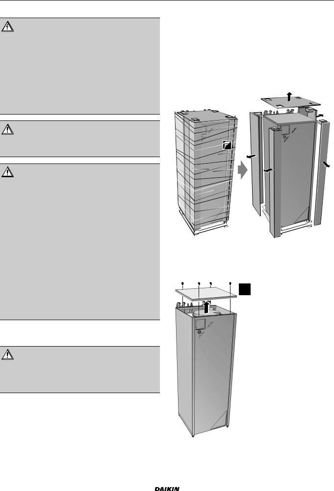
3.1.1 To unpack the indoor unit
3.1.2To remove the accessories from the indoor unit
1Remove the screws at the top of the unit.
2Remove the top panel.
4x 
3 Remove the accessories.
EHVH/X16 |
Installer reference guide |
Daikin Altherma - Low Temperature Split |
4 |
4P313777-1 – 2012.05 |
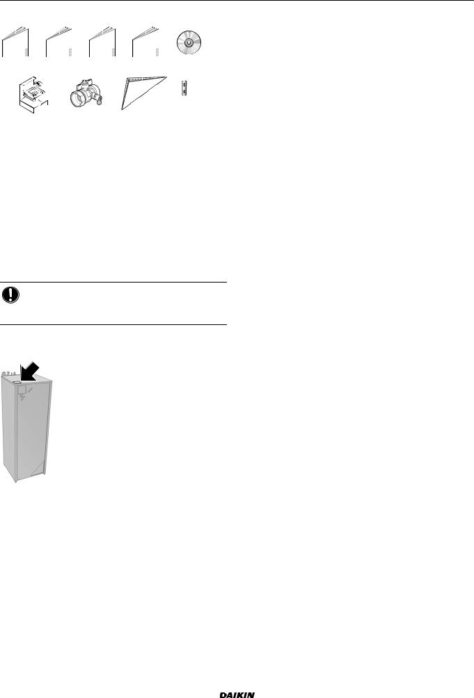
4 About the units and options
a |
b |
c |
d |
e |
|||||
|
1x |
|
1x |
|
1x |
|
1x |
|
1x |
|
|
|
|
|
|
|
|
|
|
|
|
|
|
|
|
|
|
|
|
f |
g |
h |
i |
||||
|
1x |
|
2x |
|
1x |
|
2x |
|
|
|
|
|
|
|
|
|
|
|
|
|
|
|
|
aGeneral safety precautions
bAddendum book for optional equipment
cIndoor unit installation manual
dOperation manual
eCD
fUser interface kit: user interface, 4 fixing screws, 2 plugs
gShut-off valve
hUser interface cover
iHinges for user interface cover
4 Reinstall the top panel.
4 About the units and options
4.1Identification
NOTICE
When installing or servicing several units at the same time, make sure NOT to switch the service panels between different models.
4.1.1 Identification label: Indoor unit
Location
Model identification
Example: E HV H 04 S 18 CA 3V
Code |
Description |
E |
European model |
|
|
HV |
HV=Floor-standing indoor unit with integrated tank |
|
|
H |
H=Heating only |
|
X=Heating/cooling |
|
|
04 |
Capacity class: |
|
04=4.5 kW |
|
08=7.5 kW |
|
16=16 kW |
|
|
S |
Integrated tank material: |
|
S=Stainless steel |
|
|
18 |
Integrated tank volume: |
|
18=180 l |
|
26=260 l |
|
|
CA |
Series |
|
|
3V |
Backup heater model |
|
3V |
|
9W |
|
|
4.2Possible combinations of units and options
4.2.1 List of options for indoor unit
User interface (EKRUCAL1, EKRUCAL2)
The user interface is delivered as an accessory with the unit. An additional user interface is optionally available.
The additional user interface can be connected:
To have both:
control close to the indoor unit
room thermostat functionality in the principal space to be heated
To have an interface containing other languages
The additional user interface EKRUCAL1 contains the 6 common languages: English, German, French, Dutch, Italian, Spanish.
The additional user interface EKRUCAL2 contains other languages: English, Swedish, Norwegian, Czech, Turkish, Portuguese.
Languages on the user interface can be uploaded by PC software or copied from an user interface to the other.
For installation instructions, see "7.4.5 To connect the user interface" on page 27.
Room thermostat (EKRTWA, EKRTR1)
You can connect an optional room thermostat to the indoor unit. This thermostat can either be wired (EKRTWA) or wireless (EKRTR1).
For installation instructions, see the installation manual of the room thermostat and addendum book for optional equipment.
Remote sensor for wireless thermostat (EKRTETS)
You can use a wireless indoor temperature sensor (EKRTETS) only in combination with the wireless thermostat (EKRTR1).
For installation intructions, see the installation manual of the room thermostat and addendum book for optional equipment.
Digital I/O PCB (EKRP1HB)
The digital I/O PCB is required to provide following signals: Alarm output
Space heating/cooling On/OFF output Changeover to external heat source
Only for EHVH/X16 models: Control signal for bottom plate heater kit EKBPHTH16A
For installation instructions, see the installation manual of the digital I/O PCB and addendum book for optional equipment.
Installer reference guide |
EHVH/X16 |
5 |
Daikin Altherma - Low Temperature Split |
4P313777-1 – 2012.05 |
5 Application guidelines
Demand PCB (EKRP1AHTA)
To enable the power saving consumption control by digital inputs you must install the demand PCB.
For installation instructions, see the installation manual of the demand PCB and addendum book for optional equipment.
Remote indoor sensor (KRCS01-1)
By default the internal user interface sensor will be used as room temperature sensor.
As an option the remote indoor sensor can be installed to measure the room temperature on another location.
For installation instructions, see the installation manual of the remote indoor sensor and addendum book for optional equipment.
INFORMATION
The remote indoor sensor can only be used in case the user interface is configured with room thermostat functionality.
You can only connect either the remote indoor sensor or the remote outdoor sensor.
Remote outdoor sensor (EKRSCA1)
By default the sensor inside the outdoor unit will be used to measure the outdoor temperature.
As an option the remote outdoor sensor can be installed to measure the outdoor temperature on another location (e.g. to avoid direct sunlight) to have an improved system behaviour.
For installation instructions, see the installation manual of the remote outdoor sensor.
INFORMATION
You can only connect either the remote indoor sensor or the remote outdoor sensor.
PC configurator (EKPCCAB1)
The PC cable makes a connection between the switch box of the indoor unit and a PC. It gives the possibility to upload different language files to the user interface and indoor parameters to the indoor unit. For the available language files, contact your local dealer. The software and corresponding operating instructions are available on Daikin Extranet.
For installation instructions, see the installation manual of the PC cable.
4.2.2 Possible combinations of indoor unit and outdoor unit
|
|
Indoor unit |
|
|
Outdoor unit |
|
|
|
|
EHVH16S18CA3V |
EHVX16S18CA3V |
EHVH16S26CA9W |
EHVX16S26CA9W |
|
ERHQ011BAV3 |
O |
O |
O |
O |
|
|
|
|
|
ERHQ014BAV3 |
O |
O |
O |
O |
|
|
|
|
|
ERHQ016BAV3 |
O |
O |
O |
O |
|
|
|
|
|
ERLQ011CAV3 |
O |
O |
O |
O |
|
|
|
|
|
ERLQ014CAV3 |
O |
O |
O |
O |
|
|
|
|
|
ERLQ016CAV3 |
O |
O |
O |
O |
|
|
|
|
|
ERHQ011BAW1 |
O |
O |
O |
O |
|
|
|
|
|
ERHQ014BAW1 |
O |
O |
O |
O |
|
|
|
|
|
ERHQ016BAW1 |
O |
O |
O |
O |
|
|
|
|
|
ERLQ011CAW1 |
O |
O |
O |
O |
|
|
|
|
|
ERLQ014CAW1 |
O |
O |
O |
O |
|
|
|
|
|
ERLQ016CAW1 |
O |
O |
O |
O |
|
|
|
|
|
5 Application guidelines
5.1Overview: Application guidelines
The purpose of the application guidelines is to give a glance of the possibilities of the Daikin heat pump system.
NOTICE
The illustrations in the application guidelines are meant for reference only, and are NOT to be used as detailed hydraulic diagrams. The detailed hydraulic dimensioning and balancing are NOT shown, and are the responsibility of the installer.
For more information about the configuration settings to optimize heat pump operation, see the configuration chapter.
This chapter contains applications guidelines for: Setting up the space heating/cooling system
Setting up an auxiliary heat source for space heating Setting up the domestic hot water tank
Setting up the energy metering Setting up the power consumption
Setting up an external temperature sensor
5.2Setting up the space heating/cooling system
The Daikin heat pump system supplies leaving water to heat emitters in one or more rooms.
Because the system offers a wide flexibility to control the temperature in each room, you need to answer the following questions first:
How many rooms are heated (or cooled) by the Daikin heat pump system?
Which heat emitter types are used in each room and what is their design leaving water temperature?
Once the space heating/cooling requirements are clear, Daikin recommends to follow the setup guidelines below.
EHVH/X16 |
Installer reference guide |
Daikin Altherma - Low Temperature Split |
6 |
4P313777-1 – 2012.05 |
5 Application guidelines
5.2.1 Single room
Under floor heating or radiators – Wired room thermostat
Setup
A
B
 a
a
AMain leaving water temperature zone
BOne single room
a User interface used as room thermostat
The under floor heating or radiators are directly connected to the indoor unit.
The room temperature is controlled by the user interface, which is used as room thermostat. Possible installations:
User interface (standard equipment) installed in the room and used as room thermostat
User interface (standard equipment) installed at the indoor unit and used for control close to the indoor unit + user interface (optional equipment EKRUCAL) installed in the room and used as room thermostat
Configuration |
|
|
|
Setting |
Value |
Unit temperature control: |
2 (RT control): Unit operation is |
#: [A.2.1.7] |
decided based on the ambient |
Code: [C-07] |
temperature of the user interface. |
|
|
|
|
Number of water temperature |
0 (1 LWT zone): Main |
zones: |
|
#: [A.2.1.8] |
|
Code: [7-02] |
|
|
|
Benefits
Cost effective. You do NOT need an additional external room thermostat.
Highest comfort and efficiency. The smart room thermostat functionality can decrease or increase the desired leaving water temperature based on the actual room temperature (modulation). This results in:
Stable room temperature matching the desired temperature (higher comfort)
Less ON/OFF cycles (more quiet, higher comfort and higher efficiency)
Lowest possible leaving water temperature (higher efficiency)
Easy. You can easily set the desired room temperature via the user interface:
For your daily needs, you can use preset values and schedules.
To deviate from your daily needs, you can temporarily overrule the preset values and schedules, use the holiday mode…
Under floor heating or radiators – Wireless room thermostat
Setup
A
B
 a
a 


 b
b
AMain leaving water temperature zone
BOne single room
aReceiver for wireless external room thermostat
bWireless external room thermostat
The under floor heating or radiators are directly connected to the indoor unit.
The room temperature is controlled by the wireless external room thermostat (optional equipment EKRTR1).
Configuration |
|
|
|
|
|
|
|
|
|
Setting |
|
Value |
|
|
Unit temperature control: |
1 (Ext RT control): Unit operation |
|||
#: [A.2.1.7] |
is decided by the external |
|||
Code: [C-07] |
thermostat. |
|
|
|
|
|
|
|
|
|
|
|
||
Number of water temperature |
0 (1 LWT zone): Main |
|
||
zones: |
|
|
|
|
#: [A.2.1.8] |
|
|
|
|
Code: [7-02] |
|
|
|
|
|
|
|||
External room thermostat for the |
Configure according to the setup: |
|||
main zone: |
1 (Thermo ON/OFF): When |
|||
#: [A.2.2.4] |
the |
used |
external room |
|
Code: [C-05] |
thermostat |
or heat pump |
||
|
convector can only send a |
|||
|
thermo ON/OFF |
condition. |
||
|
No |
separation |
between |
|
|
heating or cooling demand. |
|||
|
2 (C/H request): When the |
|||
|
used |
external |
room |
|
|
thermostat |
can |
send a |
|
|
separate |
heating/cooling |
||
|
thermo ON/OFF condition. |
|||
|
|
|
|
|
Benefits
Wireless. The Daikin external room thermostat is available in a wireless version.
Efficiency. Although the external room thermostat only sends ON/OFF signals, it is specifically designed for the heat pump system.
Comfort. In case of under floor heating, the wireless external room thermostat prevents condensation on the floor during cooling operation by measuring the room humidity.
Installer reference guide |
EHVH/X16 |
7 |
Daikin Altherma - Low Temperature Split |
4P313777-1 – 2012.05 |
5 Application guidelines
Heat pump convectors
Setup
A
B
 a
a
AMain leaving water temperature zone
BOne single room
a Remote controller of the heat pump convectors
The heat pump convectors are directly connected to the indoor unit.
The desired room temperature is set via the remote controller of the heat pump convectors.
The space heating/cooling demand signal is sent to one digital input on the indoor unit (X2M/1 and X2M/4).
The space operation mode is sent to the heat pump convectors by one digital output on the indoor unit (X2M/33 and X2M/34).
INFORMATION
When using multiple heat pump convectors, make sure each one receives the infrared signal from the remote controller of the heat pump convectors.
Configuration |
|
|
|
|
|
Setting |
Value |
|
Unit temperature control: |
1 (Ext RT control): Unit operation |
|
#: [A.2.1.7] |
is decided by the external |
|
Code: [C-07] |
thermostat. |
|
|
||
|
|
|
Number of water temperature |
0 (1 LWT zone): Main |
|
zones: |
|
|
#: [A.2.1.8] |
|
|
Code: [7-02] |
|
|
|
|
|
External room thermostat for the |
1 (Thermo ON/OFF): When the |
|
main zone: |
used external room thermostat or |
|
#: [A.2.2.4] |
heat pump convector can only |
|
Code: [C-05] |
send a thermo ON/OFF |
|
condition. No separation |
||
|
||
|
between heating or cooling |
|
|
demand. |
Benefits
Cooling. The heat pump convector offers, besides heating capacity, also excellent cooling capacity.
Efficiency. Optimal energy efficiency because of the interlink function.
Stylish.
Combination: Under floor heating + Heat pump convectors
Space heating is provided by: The under floor heating The heat pump convectors
Space cooling is provided by the heat pump convectors only. The under floor heating is shut off by the shut-off valve.
Setup
A |
B |
M1 |
a |
AMain leaving water temperature zone
BOne single room
a Remote controller of the heat pump convectors
The heat pump convectors are directly connected to the indoor unit.
A shut-off valve (field supply) is installed before the under floor heating to prevent condensation on the floor during cooling operation.
The desired room temperature is set via the remote controller of the heat pump convectors.
The space heating/cooling demand signal is sent to one digital input on the indoor unit (X2M/1 and X2M/4)
The space operation mode is sent by one digital output (X2M/33 and X2M/34) on the indoor unit to:
The heat pump convectors The shut-off valve
Configuration
Setting |
Value |
|
Unit temperature control: |
1 (Ext RT control): Unit operation |
|
#: [A.2.1.7] |
is decided by the external |
|
Code: [C-07] |
thermostat. |
|
|
||
|
|
|
Number of water temperature |
0 (1 LWT zone): Main |
|
zones: |
|
|
#: [A.2.1.8] |
|
|
Code: [7-02] |
|
|
|
|
|
External room thermostat for the |
1 (Thermo ON/OFF): When the |
|
main zone: |
used external room thermostat or |
|
#: [A.2.2.4] |
heat pump convector can only |
|
Code: [C-05] |
send a thermo ON/OFF |
|
condition. No separation |
||
|
||
|
between heating or cooling |
|
|
demand. |
|
|
|
Benefits
Cooling. Heat pump convectors provide, besides heating capacity, also excellent cooling capacity.
Efficiency. Under floor heating has the best performance with Altherma LT.
Comfort. The combination of the two heat emitter types provides:
The excellent heating comfort of the under floor heating The excellent cooling comfort of the heat pump convectors
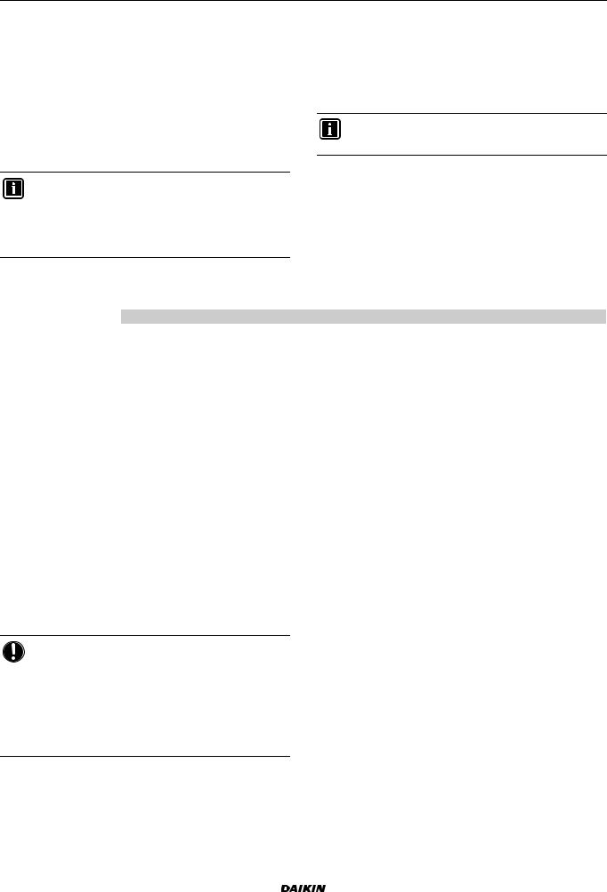
5.2.2 Multiple rooms – One LWT zone
If only one leaving water temperature zone is needed because the design leaving water temperature of all heat emitters is the same, you do NOT need a mixing valve station (cost effective).
Example: If the heat pump system is used to heat up one floor where all the rooms have the same heat emitters.
EHVH/X16 |
Installer reference guide |
Daikin Altherma - Low Temperature Split |
8 |
4P313777-1 – 2012.05 |
5 Application guidelines
Under floor heating or radiators – Thermostatic valves
If you are heating up rooms with under floor heating or radiators, a very common way is to control the temperature of the main room by using a thermostat (this can either be the user interface or an external room thermostat), while the other rooms are controlled by so-called thermostatic valves, which open or close depending on the room temperature.
Setup
A |
|
B |
C |
|
T |
|
a |
AMain leaving water temperature zone
BRoom 1
CRoom 2
a User interface
The under floor heating of the main room is directly connected to the indoor unit.
The room temperature of the main room is controlled by the user interface used as thermostat.
A thermostatic valve is installed before the under floor heating in each of the other rooms.
NOTICE
Mind situations where the main room can be heated by another heating source. Example: Fireplaces.
Configuration |
|
|
|
Setting |
Value |
Unit temperature control: |
2 (RT control): Unit operation is |
#: [A.2.1.7] |
decided based on the ambient |
Code: [C-07] |
temperature of the user interface. |
|
|
|
|
Number of water temperature |
0 (1 LWT zone): Main |
zones: |
|
#: [A.2.1.8] |
|
Code: [7-02] |
|
|
|
Benefits
Cost effective.
Easy. Same installation as for one room, but with thermostatic valves.
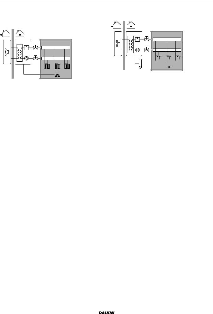
Under floor heating or radiators – Multiple external room thermostats
Setup
A
BC
M1 |
b |
M2 |
 a
a  a
a
AMain leaving water temperature zone
BRoom 1
CRoom 2
aExternal room thermostat
bBypass valve
For each room, a shut-off valve (field supplied) is installed to avoid leaving water supply when there is no heating or cooling demand.
A bypass valve must be installed to make water recirculation possible when all shut-off valves are closed.
The user interface connected to the indoor unit decides the space operation mode. Mind that the operation mode on each room thermostat must be set to match the indoor unit.
The room thermostats are connected to the shut-off valves, but do NOT have to be connected to the indoor unit. The indoor unit will supply leaving water all the time, with the possibility to program a leaving water schedule.
Configuration |
|
|
|
Setting |
Value |
Unit temperature control: |
0 (LWT control): Unit operation is |
#: [A.2.1.7] |
decided based on the leaving |
Code: [C-07] |
water temperature. |
|
|
|
|
Number of water temperature |
0 (1 LWT zone): Main |
zones: |
|
#: [A.2.1.8] |
|
Code: [7-02] |
|
|
|
Benefits
Compared with under floor heating or radiators for one room: Comfort. You can set the desired room temperature, including schedules, for each room via the room thermostats.
Heat pump convectors
Setup
A
BC
 a
a  a
a
AMain leaving water temperature zone
BRoom 1
B Room 2
a Remote controller of the heat pump convectors
The desired room temperature is set via the remote controller of the heat pump convectors.
Installer reference guide |
EHVH/X16 |
9 |
Daikin Altherma - Low Temperature Split |
4P313777-1 – 2012.05 |
5 Application guidelines
The user interface connected to the indoor unit decides the space operation mode.
The heating or cooling demand signals of each heat pump convector are connected in parallel to the digital input on the indoor unit (X2M/1 and X2M/4). The indoor unit will only supply leaving water temperature when there is an actual demand.
NOTICE
To increase comfort and performance, Daikin recommends to install the valve kit option EKVKHPC on each heat pump convector.
Configuration |
|
|
|
Setting |
Value |
Unit temperature control: |
1 (Ext RT control): Unit operation |
#: [A.2.1.7] |
is decided by the external |
Code: [C-07] |
thermostat. |
|
|
|
|
Number of water temperature |
0 (1 LWT zone): Main |
zones: |
|
#: [A.2.1.8] |
|
Code: [7-02] |
|
|
|
Benefits
Compared with heat pump convectors for one room:
Comfort. You can set the desired room temperature, including schedules, for each room via the remote controller of the heat pump convectors.
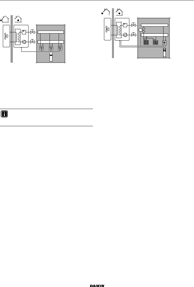
Combination: Under floor heating + Heat pump convectors
Setup
A |
|
B |
C |
M1 |
|
M1 |
|
|
b |
|
a |
AMain leaving water temperature zone
BRoom 1
CRoom 2
aExternal room thermostat
bRemote controller of the heat pump convectors
For each room with heat pump convectors: The heat pump convectors are directly connected to the indoor unit.
For each room with under floor heating: Two shut-off valves (field supply) are installed before the under floor heating:
A shut-off valve to prevent hot water supply when the room has no heating demand
A shut-off valve to prevent condensation on the floor during cooling operation of the rooms with heat pump convectors
For each room with heat pump convectors: The desired room temperature is set via the remote controller of the heat pump convectors.
For each room with under floor heating: The desired room temperature is set via the external room thermostat (wired or wireless).
The user interface connected to the indoor unit decides the space operation mode. Mind that the operation mode on each external room thermostat and remote controller of the heat pump convectors must be set to match the indoor unit.
NOTICE
To increase comfort and performance, Daikin recommends to install the valve kit option EKVKHPC on each heat pump convector.
Configuration |
|
|
|
Setting |
Value |
Unit temperature control: |
0 (LWT control): Unit operation is |
#: [A.2.1.7] |
decided based on the leaving |
Code: [C-07] |
water temperature. |
|
|
|
|
Number of water temperature |
0 (1 LWT zone): Main |
zones: |
|
#: [A.2.1.8] |
|
Code: [7-02] |
|
|
|
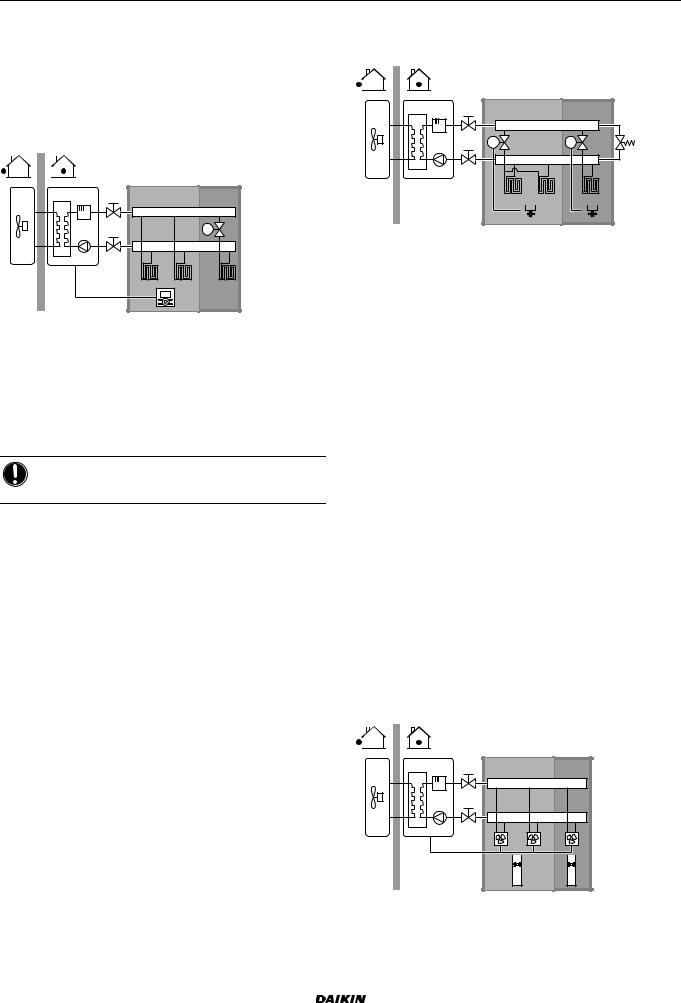
5.2.3 Multiple rooms – Two LWT zones
If the heat emitters selected for each room are designed for different leaving water temperatures, you can use different leaving water temperature zones (maximum 2).
In this document:
Main zone = Zone with the lowest design temperature in heating, and the highest design temperature in cooling Additional zone = The other zone
CAUTION
When there is more than one leaving water zone, you must always install a mixing valve station in the main zone to decrease (in heating)/increase (in cooling) the leaving water temperature when the additional zone has demand.
Typical example:
|
Heat emitters: Design |
Room (zone) |
temperature |
Living room (main zone) |
Under floor heating: |
|
In heating: 35°C |
|
In cooling: 20°C (only |
|
refreshment, no real cooling |
|
allowed) |
|
|
Bed rooms (additional zone) |
Heat pump convectors: |
|
In heating: 45°C |
|
In cooling: 12°C |
|
|
Setup
A
B C
|
a |
a |
c |
D |
|
E |
|
|
|
|
b |
EHVH/X16 |
Installer reference guide |
Daikin Altherma - Low Temperature Split |
10 |
4P313777-1 – 2012.05 |
5 Application guidelines
AAdditional leaving water temperature zone
BRoom 1
CRoom 2
DMain leaving water temperature zone
ERoom 3
aRemote controller of the heat pump convectors
bUser interface
cMixing valve station
For the main zone:
A mixing valve station is installed before the under floor heating.
The pump of the mixing valve station is controlled by the ON/OFF signal on the indoor unit (X2M/5 and X2M/7; normal closed shut-off valve output).
The room temperature is controlled by the user interface, which is used as room thermostat.
For the additional zone:
The heat pump convectors are directly connected to the indoor unit.
The desired room temperature is set via the remote controller of the heat pump convectors for each room.
The heating or cooling demand signals of each heat pump convector are connected in parallel to the digital input on the indoor unit (X2M/1 and X2M/4). The indoor unit will only supply the desired additional leaving water temperature when there is an actual demand.
The user interface connected to the indoor unit decides the space operation mode. Mind that the operation mode on each remote controller of the heat pump convectors must be set to match the indoor unit.
Configuration |
|
|
|
|
|
|
|
|
|
Setting |
|
Value |
|
|
Unit temperature control: |
2 (RT control): Unit operation is |
|||
#: [A.2.1.7] |
decided based on the ambient |
|||
Code: [C-07] |
temperature of the user interface. |
|||
Note: |
|
|
||
|
|
|
||
|
Main room = user interface |
|||
|
used |
as room |
thermostat |
|
|
functionality |
|
||
|
Other |
rooms |
= external |
|
|
room |
|
thermostat |
|
|
functionality |
|
||
|
|
|||
Number of water temperature |
1 (2 LWT zones): Main + |
|||
zones: |
additional |
|
|
|
#: [A.2.1.8] |
|
|
|
|
Code: [7-02] |
|
|
|
|
|
|
|||
In case of heat pump convectors: |
1 (Thermo ON/OFF): When the |
|||
External room thermostat for the |
used external room thermostat or |
|||
additional zone: |
heat pump convector can only |
|||
#: [A.2.2.5] |
send a thermo ON/OFF |
|||
Code: [C-06] |
condition. No separation |
|||
between heating or cooling |
||||
|
||||
|
demand. |
|
|
|
|
|
|||
Shut-off valve output |
Set to follow the thermo demand |
|||
|
of the main zone. |
|
||
|
|
|||
Shut-off valve |
If the main zone must be shut off |
|||
|
during cooling mode to prevent |
|||
|
condensation on the floor, set it |
|||
|
accordingly. |
|
||
|
|
|||
At the mixing valve station |
Set the desired main leaving |
|||
|
water temperature for heating |
|||
|
and/or cooling. |
|
||
|
|
|
|
|
Benefits Comfort.
The smart room thermostat functionality can decrease or increase the desired leaving water temperature based on the actual room temperature (modulation).
The combination of the two heat emitter systems provides the excellent heating comfort of the under floor heating, and the excellent cooling comfort of the heat pump convectors.
Efficiency.
Depending on the demand, the indoor unit supplies different leaving water temperature matching the design temperature of the different heat emitters.
Under floor heating has the best performance with Altherma LT.
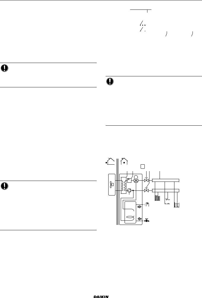
5.3Setting up an auxiliary heat source for space heating
Space heating can be done by: The indoor unit
An auxiliary boiler (field supply) connected to the system
When the room thermostat requests heating, the indoor unit or the auxiliary boiler starts operating depending on the outdoor temperature (status of the changeover to external heat source). When the permission is given to the auxiliary boiler, the space heating by the indoor unit is turned OFF.
Bivalent operation is only possible for space heating, NOT for domestic hot water production. Domestic hot water is always produced by the DHW tank connected to the indoor unit.
INFORMATION |
|
|
During heating operation |
of the |
heat pump, the |
heat pump operates to |
achieve |
the desired |
temperature set via the user interface. When weatherdependent operation is active, the water temperature is determined automatically depending on the outdoor temperature.
During heating operation of the auxiliary boiler, the auxiliary boiler operates to achieve the desired water temperature set via the auxiliary boiler controller.
Setup
Integrate the auxiliary boiler as follows:
a |
b c d e f g |
h |
j |
M
h 
 i
i 
f |
k |
li 
n
|
FHL1 |
|
|
|
|
|
|
|
|
|
|
|
|
|
|
||
|
FHL2 |
|
|
|
||||
|
|
|
|
|
|
|
|
|
m |
|
|
|
FHL3 |
||||
|
|
|
|
|
|
|
|
|
Installer reference guide |
EHVH/X16 |
11 |
Daikin Altherma - Low Temperature Split |
4P313777-1 – 2012.05 |
5 Application guidelines
aOutdoor unit
bIndoor unit
cHeat exchanger
dBackup heater
ePump
fShut-off valve
gMotorised 3-way valve (delivered with DHW tank)(field supply)
hNon-return valve
iShut-off valve
jCollector (field supply)
kAuxiliary boiler (field supply)
lAquastat valve (field supply)
mDHW tank (option)
nHeat exchanger coil
FHL1...3 Under floor heating
NOTICE
Make sure the auxiliary boiler and its integration in the system complies with applicable legislation.
Daikin is NOT responsible for incorrect or unsafe situations in the auxiliary boiler system.
Make sure the return water to the heat pump does NOT exceed 55°C. To do so:
Set the desired water temperature via the auxiliary boiler controller to maximum 55°C.
Install an aquastat valve in the return water flow of the heat pump.
Set the aquastat valve to close above 55°C and to open below 55°C.
Install non-return valves.
Make sure to only have one expansion vessel in the water circuit. An expansion vessel is already is already premounted in the indoor unit.
Install the digital I/O PCB (option EKRP1HB).
Connect X1 and X2 (changeover to external heat source) on the PCB to the auxiliary boiler thermostat.
To setup the heat emitters, see setting up the space heating/cooling application guidelines).
Configuration
Via the user interface (quick wizard):
Set the use of a bivalent system as external heat source. Set the bivalent temperature and hysteresis.
NOTICE
Make sure the bivalent hysteresis has enough differential to prevent frequent changeover between indoor unit and auxiliary boiler.
Because the outdoor temperature is measured by the outdoor unit air thermistor, install the outdoor unit in the shadow so that it is NOT influenced or turned ON/OFF by direct sunlight.
Frequent changeover may cause corrosion of the auxiliary boiler. Contact the manufacturer of the auxiliary boiler for more information.
Changeover to external heat source decided by an auxiliary contact
Only possible in external room thermostat control AND one leaving water temperature zone (see setting up space heating/cooling application guideline).
The auxiliary contact can be:
An outdoor temperature thermostat An electricity tariff contact
A manually operated contact
…
Setup: Connect the following field wiring:
L
|
|
|
|
|
|
|
|
|
|
|
|
|
|
|
|
|
|
|
|
|
|
|
|
|
|
|
|
|
|
|
|
H |
|
Com |
|
|
|
|
|
|
|||||||||||
|
|
|
|
|
|
|
|
|
|
|
|
|
|
|
Indoor |
|
|
|
|
|
|||||
Indoor/Auto/Boiler |
|
|
|
|
|
|
|
|
|
|
|
|
BTI |
||||||||||||
|
|
|
|
|
|
|
|
|
|
|
|
||||||||||||||
|
|
|
|
|
|
|
|
|
|
|
|
X2M |
|
||||||||||||
|
|
|
|
|
|
|
|
|
|
|
|
|
|
1 |
2 |
3 |
4 |
|
|
X |
Y |
||||
|
|
|
|
|
|
A |
|
|
|
|
|
|
|
|
|
|
|
|
|
|
|
|
|
||
|
|
|
|
|
|
|
|
|
|
|
|
|
K1A |
|
|
K2A |
|
|
|||||||
|
|
|
|
|
|
|
|
|
|
|
|
|
|
|
|
||||||||||
N |
|
K1A |
|
|
K2A |
|
|
|
|
|
|
|
|
|
|||||||||||
|
|
|
|
|
|
|
|
|
|
||||||||||||||||
|
|
|
|
|
|
|
|
|
|
|
|
|
|
|
|
|
|
|
|
|
|
|
|
|
|
|
|
|
|
|
|
|
|
|
|
|
|
|
|
|
|
|
|
|
|
|
|
|
|
|
|
BTI |
Boiler thermostat input |
|
|
|
|
|
|||||||||||||||||||
A |
Auxiliary contact (normal closed) |
|
|
|
|
|
|||||||||||||||||||
H |
Heating demand room thermostat (optional) |
|
|
|
|
|
|||||||||||||||||||
K1A |
Auxiliary relay for activation of indoor unit (field supply) |
||||||||||||||||||||||||
K2A |
Auxiliary relay for activation of boiler (field supply) |
||||||||||||||||||||||||
Indoor |
Indoor unit |
|
|
|
|
|
|
|
|
|
|
|
|
|
|
|
|
|
|||||||
Auto |
Automatic |
|
|
|
|
|
|
|
|
|
|
|
|
|
|
|
|
|
|||||||
Boiler |
Boiler |
|
|
|
|
|
|
|
|
|
|
|
|
|
|
|
|
|
|||||||
NOTICE
Make sure the auxiliary contact has enough differential or time delay to prevent frequent changeover between indoor unit and auxiliary boiler.
If the auxiliary contact is an outdoor temperature thermostat, install the thermostat in the shadow so that it is NOT influenced or turned ON/OFF by direct sunlight.
Frequent changeover may cause corrosion of the auxiliary boiler. Contact the manufacturer of the auxiliary boiler for more information.
5.4Setting up the domestic hot water tank
The DHW tank can be:
Integrated in the indoor unit
Installed standalone as option
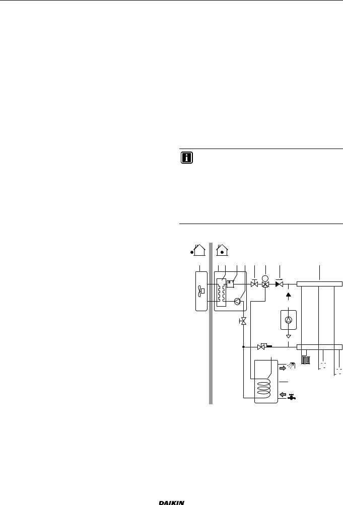
5.4.1 System layout – Integrated DHW tank
a |
b c d f |
|
UI |
i |
|||
|
h h |
||||||
|
|
|
|
|
|
|
|
|
|
|
|
|
|
|
|
M
e
FHL1 


 FHL2
FHL2 


 FHL3
FHL3

 g
g
aOutdoor unit
bIndoor unit
cHeat exchanger
dBackup heater
ePump
fMotorised 3-way valve
gDHW tank
hShut-off valve
iCollector (field supply) FHL1...3 Under floor heating
UI User interface
EHVH/X16 |
Installer reference guide |
Daikin Altherma - Low Temperature Split |
12 |
4P313777-1 – 2012.05 |
5 Application guidelines
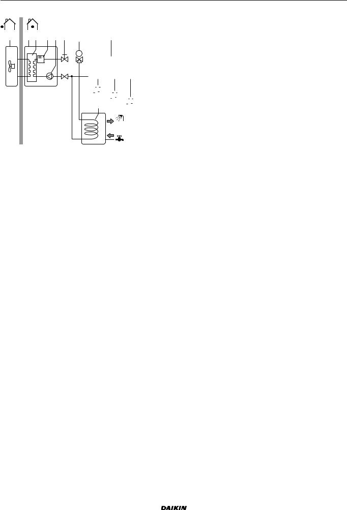
5.4.2 System layout – Standalone DHW tank
a |
b c d e f |
g |
h |
M
|
|
|
|
|
|
|
|
|
|
|
|
|
|
|
|
|
|
|
|
|
|
|
|
|
|
|
|
|
|
|
|
|
|
|
|
|
|
|
|
|
|
|
|
|
|
|
|
|
|
|
|
|
|
|
|
|
|
|
|
|
|
|
|
|
|
|
|
|
|
|
|
|
|
|
|
|
|
|
|
|
|
|
|
|
|
|
|
|
|
f |
|
|
|
|
|
|
|
|
|
|
|
|
|
|
|
|
|
|
|
|
|
|
|
|
|
|
|
|
|
|
|
|
|
||
|
|
|
|
|
FHL1 |
|
|
|
|
|
|
|
|||||
|
|
|
|
|
|
|
i j |
|
FHL2 |
|
|
|
|||||
|
|
|
|
|
|
|
|
|
|
|
|
|
|
||||
|
|
|
|
|
FHL3 |
||||||||||||
|
|
|
|
|
|
|
|
|
|
|
|
|
|
||||
|
|
|
|
|
|
|
|
|
|
|
|
|
|
|
|
|
|
aOutdoor unit
bIndoor unit
cHeat exchanger
dBackup heater
ePump
fShut-off valve
gMotorised 3-way valve
hCollector (field supply)
iDHW tank
jHeat exchanger coil FHL1...3 Under floor heating
5.4.3Selecting the volume and desired temperature for the DHW tank
People experience water as hot when its temperature is 40°C. Therefore, the DHW consumption is always expressed as equivalent hot water volume at 40°C. However, you can set the DHW tank temperature at a higher temperature (example: 53°C), which is then mixed with cold water (example: 15°C).
Selecting the volume and desired temperature for the DHW tank consists of:
1Determining the DHW consumption (equivalent hot water volume at 40°C).
2Determining the volume and desired temperature for the DHW tank.
Possible DHW tank volumes |
|
|
|
Type |
Possible volumes |
Integrated DHW tank |
180 l |
|
260 l |
|
|
Standalone DHW tank |
150 l |
|
200 l |
|
300 l |
|
|
Energy saving tips
If the DHW consumption differs from day to day, you can program a weekly schedule with different desired DHW tank temperatures for each day.
The lower the desired DHW tank temperature, the more cost effective. By selecting a larger DHW tank, you can lower the desired DHW tank temperature.
The heat pump itself can produce domestic hot water of maximum 55°C (50°C if outdoor temperature is low). The electrical resistance integrated in the heat pump can higher this temperature. However, this consumes more energy. Daikin recommends to set the desired DHW tank temperature below 55°C to avoid using the electrical resistance.
The higher the outdoor temperature, the better the performance of the heat pump.
If energy prices are the same during the day and the night, Daikin recommends to heat up the DHW tank during the day.
If energy prices are lower during the night, Daikin recommends to heat up the DHW tank during the night.
When the heat pump produces domestic hot water, it cannot heat up a space. When you need domestic hot water and space heating at the same, Daikin recommends to produce the domestic hot water during the night when there is lower space heating demand.
Determining the DHW consumption
Answer the following questions and calculate the DHW consumption (equivalent hot water volume at 40°C) using the typical water volumes:
Question |
Typical water volume |
How many showers are needed |
1 shower = 10 min x 10 l/min = |
per day? |
100 l |
|
|
How many baths are needed per |
1 bath = 150 l |
day? |
|
|
|
How much water is needed at the |
1 sink = 2 min x 5 l/min = 10 l |
kitchen sink per day? |
|
|
|
Are there any other domestic hot |
— |
water needs? |
|
|
|
Example: If the DHW consumption of a family (4 persons) per day is as follows:
3 showers
1 bath
3 sink volumes
Then the DHW consumption = (3x100 l) + (1x150 l) + (3x10 l) = 480 l
Determining the volume and desired temperature for the DHW tank
Formula |
Example |
V1 = V2 + V2 x (T2 - 40) / (40 - T1) |
If: |
|
V2 = 180 l |
|
T2 = 54°C |
|
T1 = 15°C |
|
Then V1 = 280 l |
V2 = V1 x (40 - T1) / (T2 - T1) |
If: |
|
V1 = 480 l |
|
T2 = 54°C |
|
T1 = 15°C |
|
Then V2 = 307 l |
V1: DHW consumption (equivalent hot water volume at 40°C)
V2: Required DHW tank volume if only heated once
T2: DHW tank temperature
T1: Cold water temperature
5.4.4 Setup and configuration – DHW tank
For large DHW consumptions, you can heat up the DHW tank several times during the day.
To heat up the DHW tank to the desired DHW tank temperature, you can use the following energy sources:
Thermodynamic cycle of the heat pump
Electrical backup heater (for integrated DHW tank) Electrical booster heater (for standalone DHW tank) Solar panels
For more information about:
Optimizing the energy consumption for producing domestic hot water, see the configuration chapter.
Connecting the electrical wiring of the standalone DHW tank to the indoor unit, see the installation chapter. Connecting the water piping of the standalone DHW tank to the indoor unit, see the installation manual of the DHW tank.
Installer reference guide |
EHVH/X16 |
13 |
Daikin Altherma - Low Temperature Split |
4P313777-1 – 2012.05 |
5 Application guidelines
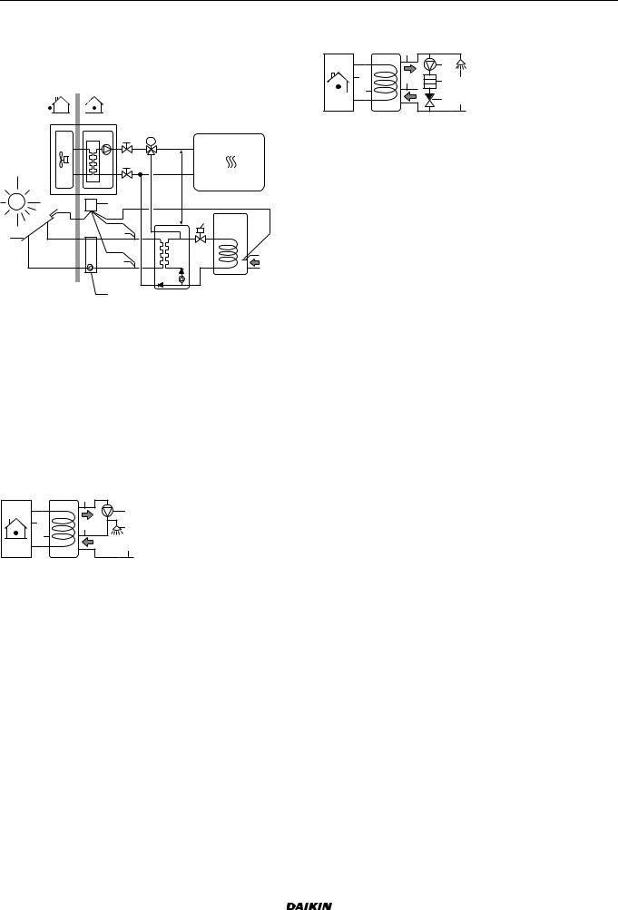
5.4.5Combination: Standalone DHW tank + Solar panels
By connecting the DHW tank to solar panels, the DHW tank can be heated by solar energy.
For installation instructions, see the installation manual of the solar kit and addendum book for optional equipment.
c.4 |
c |
a |
c.3 |
|
|
|
c.2 |
|
b |
M
<![if ! IE]><![endif]>m≥0.5
f 

 e
e
c.1
d 
aSolar panels
bSolar pump station
cSolar pump station controller with temperature sensors c1 Tank temperature sensor
c2 Return temperature sensor to solar panels
c3 Supply temperature with flow meter from solar panels
c4 Solar panel temperature sensor
dSolar kit
eDHW temperature sensor of the unit
fSolenoid 2-way valve (only for UK). Obligatory for compliance to UK building regulation G3. Heating system
Example of unit
5.4.6DHW pump for instant hot water
Setup
|
h |
|
|
|
|
c |
|
a |
i |
f |
|
b |
|||
|
g |
||
|
|
aIndoor unit
bDHW tank
cDHW pump
fShower
gCold water
hDomestic hot water OUT
iRecirculation connection
By connecting a DHW pump, instant hot water can be available at the tap.
The DHW pump and the installation are field supply and the responsibility of the installer.
For more information about connecting the recirculation connection (for integrated DHW tank), see the installation chapter.
Configuration
For more information, see the configuration chapter.
You can program a schedule to control the DHW pump via the user interface. For more information, see the user reference guide.
5.4.7 DHW pump for disinfection
Setup
|
h |
|
|
|
|
|
c |
|
|
a |
i |
d |
f |
|
b |
||||
|
e |
g |
||
|
|
aIndoor unit
bDHW tank
cDHW pump
dHeater element
eNon-return valve
fShower
gCold water
hDomestic hot water OUT
iRecirculation connection
The DHW pump and the installation are field supply and the responsibility of the installer.
For the integrated DHW tank, the temperature of the DHW tank can be set to maximum 60°C. If applicable legislation requires higher temperature for disinfection, you can connect a DHW pump and heater element as shown above.
If applicable legislation requires disinfection of the water piping until the tapping point, you can connect a DHW pump and heater element (if needed) as shown above.
Configuration
The indoor unit can control DHW pump operation. For more information, see the configuration chapter.
5.5Setting up the energy metering
Via the user interface, you can read out the following energy data:
Produced heat Consumed energy
You can read out the energy data: For space heating
For space cooling
For domestic hot water production
You can read out the energy data: Per month
Per year
5.5.1 Produced heat
Applicable for all models.
The produced heat is calculated internally based on: The leaving and entering water temperature The flow rate
The power consumption of the booster heater (if applicable) in the domestic hot water tank
Setup and configuration:
No additional equipment needed.
Only in case a booster heater is present in the system, measure its capacity (resistance measurement) and set the capacity via the user interface. Example: If you measure a booster heater resistance of 17.1 Ω, the capacity of the heater at 230 V is 3100 W.
EHVH/X16 |
Installer reference guide |
Daikin Altherma - Low Temperature Split |
14 |
4P313777-1 – 2012.05 |

5 Application guidelines
5.5.2 Consumed energy
You can use the following methods to determine the consumed energy:
Calculating
Measuring
NOTICE
You cannot combine calculating the consumed energy (example: for backup heater) and measuring the consumed energy (example: for outdoor unit). If you do so, the energy data will be invalid.
Calculating the consumed energy
Only applicable for EHBH/X04+08 and EHVH/X04+08. The consumed energy is calculated internally based on:
The actual power input of the outdoor unit
The set capacity of the backup heater and booster heater The voltage
Setup and configuration: To get accurate energy data, measure the capacity (resistance measurement) and set the capacity via the user interface for:
The backup heater (step 1 and step 2) The booster heater
Measuring the consumed energy
Applicable for all models.
Preferred method because of higher accuracy. Requires external power meters.
Setup and configuration:
For the specifications of each type of meter, see technical data.
When using electrical power meters, set the number of pulses/kWh for each power meter via the user interface. Consumed energy data for EHVH/X16 and EHBH/X16 models will only be available if this setting is configured.
NOTICE
When measuring the electrical power consumption, make sure ALL power input of the system is covered by the electrical power meters.
5.5.3 Normal kWh rate power supply
General rule
One power meter that covers the entire system is sufficient.
Setup
Connect the power meter to X5M/7 and X5M/8.
Power meter type |
|
|
|
In case of… |
Use a… power meter |
Single-phase outdoor unit |
Single-phase |
Backup heater supplied |
|
from a single-phase grid (i.e. |
|
the backup heater model is |
|
*3V or *9W connected to a |
|
single-phase grid) |
|
|
|
In other cases (i.e. a three-phase |
Three-phase |
outdoor unit and/or a 9W* |
|
backup heater model connected |
|
to a three-phase grid) |
|
|
|
Example
Single-phase power meter |
Three-phase power meter |
|
|
|
a |
|
|
|
a |
|
|
b |
|
|
|
|
b |
|
|
|
|
|
|
||
c |
|
c |
|
c |
|
c |
d |
d |
e |
f |
g |
e |
f |
g |
h |
A |
|
B |
C |
A |
|
B |
C |
A Outdoor unit |
A Outdoor unit |
B Indoor unit |
B Indoor unit |
C DHW tank |
C DHW tank |
a Electrical cabinet (L1/N) |
a Electrical cabinet (L1/L2/L3/N) |
b Power meter (L1/N) |
b Power meter (L1/L2/L3/N) |
c Fuse (L1/N) |
c Fuse (L1/L2/L3/N) |
d Outdoor unit (L1/N) |
d Fuse (L1/N) |
e Indoor unit (L1/N) |
e Outdoor unit (L1/L2/L3/N) |
f Backup heater (L1/N) |
f Indoor unit (L1/L2/L3/N) |
g Booster heater (L1/N) |
g Backup heater (L1/L2/L3/N) |
|
h Booster heater (L1/N) |
Exception
You can use a second power meter if:
The power range of one meter is insufficient.
The electrical meter cannot easily be installed in the electrical cabinet.
230V and 400V three-phase grids are combined (very uncommon), because of technical limitations of power meters.
Connection and setup:
Connect the second power meter to X5M/9 and X5M/10. In the software the power consumption data of both meters is added so you do NOT have to set which meter covers which power consumption. You only need to set the number of pulses of each power meter.
See preferential kWh rate power supply for an example with two power meters.
5.5.4 Preferential kWh rate power supply
General rule
Power meter 1: Measures the outdoor unit.
Power meter 2: Measures the rest (i.e. indoor unit, backup heater and optional booster heater).
Setup
Connect power meter 1 to X5M/7 and X5M/8.
Connect power meter 2 to X5M/9 and X5M/10.
Power meter types
Power meter 1: Singleor three-phase power meter according to the power supply of the outdoor unit.
Power meter 2:
In case of a single-phase backup heater configuration, use a single-phase power meter.
In other cases, use a three-phase power meter.
Installer reference guide |
EHVH/X16 |
15 |
Daikin Altherma - Low Temperature Split |
4P313777-1 – 2012.05 |
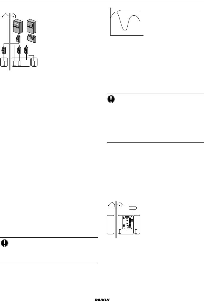
Example
Single-phase outdoor unit with a three-phase backup heater:
|
|
|
a |
|
b |
|
|
c |
|
|
d |
|
|
|
|
||
e |
|
f |
|
e |
|
g |
h |
i |
|
j |
|
A |
|
B |
|
C |
|
|
|
A |
|
Outdoor unit |
|
|
|
B |
|
Indoor unit |
|
|
|
C |
|
DHW tank |
|
|
|
a |
|
Electrical cabinet (L1/N): Preferential kWh rate power |
|
|
|
|
|
supply |
|
bElectrical cabinet (L1/L2/L3/N): Normal kWh rate power supply
cPower meter (L1/N)
dPower meter (L1/L2/L3/N)
eFuse (L1/N)
fFuse (L1/L2/L3/N)
gOutdoor unit (L1/N)
hIndoor unit (L1/L2/L3/N)
iBackup heater (L1/L2/L3/N)
jBooster heater (L1/N)
5.6Setting up the power consumption control
The power consumption control:
Is only applicable for EHBH/X04+08 and EHVH/X04+08. Allows you to limit the power consumption of the entire system (sum of outdoor unit, indoor unit, backup heater and optional booster heater).
Configuration: Set the power limitation level and how it has to be achieved via the user interface.
The power limitation level can be expressed as: Maximum running current (in A)
Maximum power input (in kW)
The power limitation level can be activated: Permanently
By digital inputs
5.6.1 Permanent power limitation
Permanent power limitation is useful to assure a maximum power or current input of the system. In some countries, legislation limits the maximum power consumption for space heating and DHW production. Example: The maximum power input depends on the area of the house and an annual fee has to be paid to the electrical company according to the size of the installed field fuse. By permanently limiting the maximum power or current of the system, you can install smaller field fuses.
NOTICE
When the current control is intended to reduce the installed field fuse sizes, the field fuse will trip to protect the field wires in case of overcurrents caused by the unit. Make sure the selection of the field fuse complies with applicable legislation.
5 Application guidelines
Pi
a
DI
|
b |
|
t |
Pi |
Power input |
t |
Time |
DI |
Digital input (power limitation level) |
aPower limitation active
bActual power input
Setup and configuration
No additional equipment needed.
Set the power consumption control settings in [A.7.2] via the user interface (for the description of all settings, see configuration chapter):
Select full time limitation mode
Select the type of limitation (power in kW or current in A) Set the desired power limitation level
NOTICE
Mind the following guidelines when selecting the desired power limitation level:
Set a minimum power consumption of ±3.6 kW to guarantee defrost operation. Otherwise, if defrosting is interrupted several times, the heat exchanger will freeze up.
Set a minimum power consumption of ±3 kW to guarantee space heating and DHW production by allowing at least one electrical heater (backup heater step 1 or booster heater).
5.6.2 Power limitation activated by digital inputs
Power limitation is also useful in combination with an energy management system.
The power or current of the entire Daikin system is limited dynamically by digital inputs (maximum four steps). Each power limitation level is set via the user interface by limiting one of the following:
Current (in A) Power input (in kW)
The energy management system (field supply) decides the activation of a certain power limitation level. Example: To limit the maximum power of the entire house (lighting, domestic appliances, space heating…).
|
|
D |
|
|
a |
|
5 |
|
|
4 |
|
|
3 |
|
|
A8P 12 |
|
|
b |
c |
A |
B |
C |
AOutdoor unit
BIndoor unit
CDHW tank
DEnergy management system
aPower limitation activation (4 digital inputs)
bBackup heater
cBooster heater
EHVH/X16 |
Installer reference guide |
Daikin Altherma - Low Temperature Split |
16 |
4P313777-1 – 2012.05 |
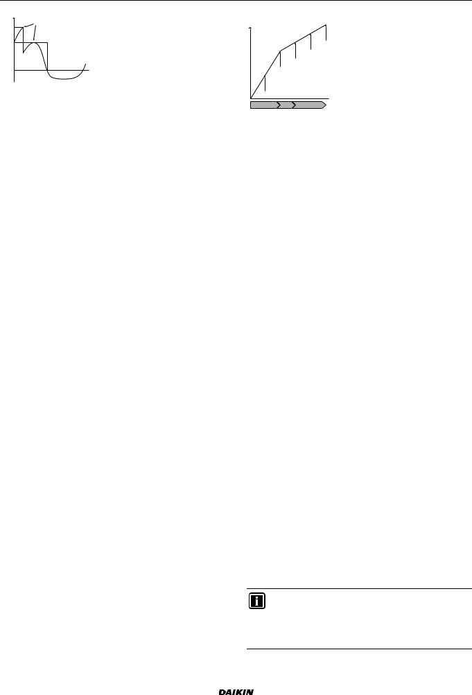
5 Application guidelines
Pi
a
DI4
DI3
b
DI1
 t
t
Pi |
Power input |
t |
Time |
DI |
Digital inputs (power limitation levels) |
aPower limitation active
bActual power input
Setup
Demand PCB (option EKRP1AHTA) needed.
Maximum four digital inputs are used to activate the corresponding power limitation level:
DI1 = strongest limitation (lowest energy consumption) DI4 = weakest limitation (highest energy consumption)
For the specification and the connection of the digital inputs, see technical data > wiring diagram.
Configuration
Set the power consumption control settings in [A.7.2] via the user interface (for the description of all settings, see configuration chapter):
Select activation by digital inputs.
Select the type of limitation (power in kW or current in A).
Set the desired power limitation level corresponding to each digital input.
5.6.3 Power limitation process
The outdoor unit has better efficiency than the electrical heaters. Therefore, the electrical heaters are limited and turned OFF first. The system limits power consumption in the following order:
1 Limits certain electrical heaters.
|
Then set the heater priority |
If… has priority |
via the user interface to… |
Domestic hot water production |
Booster heater. |
|
Result: The backup heater will |
|
be turned OFF first. |
|
|
Space heating |
Backup heater. |
|
Result: The booster heater will |
|
be turned OFF first. |
|
|
2Turns OFF all electrical heaters.
3Limits the outdoor unit
4Turns OFF the outdoor unit.
Example
If the configuration is as follows:
Power limitation level does NOT allow operation of both booster heater and backup heater (step 1 and step 2).
Heater priority = Booster heater.
Then power consumption is limited as follows:
Ph
e d
c
b
a
A B C
 Ce
Ce
Ph Produced heat
Ce Consumed energy
AOutdoor unit
BBooster heater
CBackup heater
aLimited outdoor unit operation
bFull outdoor unit operation
cBooster heater turned ON
dBackup heater step 1 turned ON
eBackup heater step 2 turned ON
5.7Setting up an external temperature sensor
You can connect one external temperature sensor. It can measure the indoor or outdoor ambient temperature. Daikin recommends to use an external temperature sensor in the following cases:
Indoor ambient temperature
In room thermostat control, the user interface is used as room thermostat and it measures the indoor ambient temperature. Therefore, the user interface must be installed on a location:
Where the average temperature in the room can be detected
That is NOT exposed to direct sunlight That is NOT near a heat source
That is NOT affected by outside air or air draught because of, for example, door opening/closing
If this is NOT possible, Daikin recommends to connect a remote indoor sensor (option KRCS01-1).
Setup: For installation instructions, see the installation manual of the remote outdoor sensor.
Configuration: Select room sensor [A.2.2.B].
Outdoor ambient temperature
In the outdoor unit, the outdoor ambient temperature is measured. Therefore, the outdoor unit must be installed on a location:
At the north side of the house or at the side of the house where the most heat emitters are located
That is NOT exposed to direct sunlight
If this is NOT possible, Daikin recommends to connect a remote outdoor sensor (option EKRSCA1).
Setup: For installation instructions, see the installation manual of the remote outdoor sensor.
Configuration: Select outdoor sensor [A.2.2.B].
During suspend (see configuration), the outdoor unit is turned down to reduce the standby energy losses. As a result, the outdoor ambient temperature is NOT read out.
If the desired leaving water temperature is weather dependent, the full time outdoor temperature measurement is important. This is another reason to install the optional outdoor ambient temperature sensor.
INFORMATION
The external outdoor ambient sensor data (either averaged or instantaneous) is used in the weather-dependent control curves and in the automatic heating/cooling changeover logic. To protect the outdoor unit, the internal sensor of the outdoor unit is always used.
Installer reference guide |
EHVH/X16 |
17 |
Daikin Altherma - Low Temperature Split |
4P313777-1 – 2012.05 |
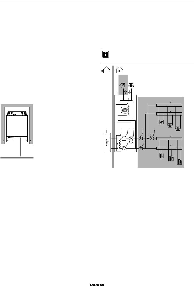
6 Preparation
6 Preparation
6.1Preparing installation site
Do NOT install the unit in places often used as work place. In case of construction works (e.g. grinding works) where a lot of dust is created, the unit must be covered.
Choose the installation location with sufficient place for carrying the unit in and out of the site.
6.1.1Installation site requirements of the indoor unit
Mind the measurement guidelines:
Maximum refrigerant piping length between indoor |
75 m(a) |
unit and outdoor unit |
|
Minimum refrigerant piping length between indoor |
3 m(b) |
unit and outdoor unit |
|
Maximum height difference between indoor unit and |
30 m |
outdoor unit |
|
|
|
(a)Check the outdoor unit installation manual.
(b)When <5 m, you need to recharge the outdoor unit (check the outdoor unit installation manual).
Mind the following spacing installation guidelines:
>10 >10
<![if ! IE]><![endif]>>500
(mm)
Do NOT install the unit in places such as:
Where there is mist of mineral oil, oil spray or vapour.
Plastic parts may deteriorate, and cause them to fall out or water to leak.
Do NOT install the unit in sound sensitive areas (e.g. near a bedroom and the like), so that the operation noise will cause no trouble.
Note: If the sound is measured under actual installation conditions, the measured value will be higher than the sound pressure level mentioned in Sound spectrum due to environmental noise and sound reflections.
The foundation must be strong enough to bear the weight of the unit. Take the weight of the unit with a domestic hot water tank full of water into account.
Make sure, in the event of a water leak, water cannot cause any damage to the installation space and surroundings.
In places with high humidity (max. RH=85%), for example a bathroom.
In places where frost is possible. Ambient temperature around the indoor unit should be >5°C.
The indoor unit is designed for indoor installation only and for ambient temperatures ranging 5~35°C in cooling mode and 5~30°C in heating mode.
6.2Preparing water piping
6.2.1 Water circuit requirements
Use the indoor unit only in a closed water system.
Using the system in an open water system will lead to excessive corrosion.
The maximum water pressure is 4 bar.
Provide adequate safeguards in the water circuit to ensure that the maximum pressure is NOT exceeded.
All installed piping and piping accessories (valve, connections,…) must withstand the following temperatures:
INFORMATION
The following illustration is an example and may NOT match your system layout.
65°C
b
jk
65°C |
i |
a |
c d |
g |
f |
|
e |
M |
f |
|
i |
|
h |
FCU1 |
|
FCU2 |
FCU3 |
|
M |
i |
|
|
|
i
FHL1
FHL2
FHL3
aOutdoor unit
bIndoor unit
cHeat exchanger
dBackup heater
ePump
fStop valve
gMotorised 3-way valve
hMotorised 2-way valve (field supply)
iCollector
jDomestic hot water tank
kHeat exchanger coil
FCU1...3 Fan coil unit (optional) FHL1...3 Floor heating loop
Make all water piping connections in accordance with the applicable legislation and the outlook diagram that is delivered with the unit, respecting the water inlet and outlet.
Do NOT use excessive force when connecting the piping. Deformation of the piping can cause malfunctioning of the unit. Provide drain taps at all low points of the system in order to allow complete drainage of the water circuit.
Provide a proper drain for the pressure relief valve to avoid water dripping out of the unit. See "7.3.2 To connect the pressure relief valve to the drain" on page 23.
Provide air vents at all high points of the system, which must also be easily accessible for servicing. An automatic air purge is provided in the indoor unit. Check that the air purge is NOT tightened too much, so that automatic release of air in the water circuit is possible.
EHVH/X16 |
Installer reference guide |
Daikin Altherma - Low Temperature Split |
18 |
4P313777-1 – 2012.05 |
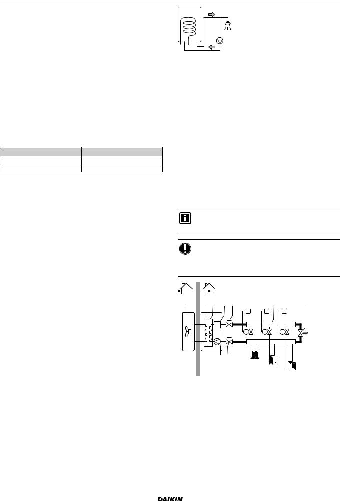
6 Preparation
Only use materials that are compatible with water used in the system and with the materials used in the indoor unit.
Check that all components in the field piping can withstand the water pressure and water temperature.
When using non-brass metallic piping, insulate the brass and non-brass properly so that they do NOT make contact with each other. This to prevent galvanic corrosion.
Never use Zn-coated parts in the water circuit. Because the unit's internal water circuit uses copper piping, excessive corrosion may occur.
Only use appropriate tooling to handle brass, which is a soft material. If NOT, pipes will get damaged.
Select the water piping diameter in relation to the required water flow and the available external static pressure of the pump. See "14 Technical data" on page 61 for the external static pressure curves of the indoor unit.
You can find the minimum required water flow for the indoor unit operation in the following table. When the water flow is lower, flow error 7H will be displayed and the indoor unit will be stopped.
Model |
Minimum water flow (l/min) |
04 |
5 |
08+16 |
11 |
When using a 2-way valve in the water circuit, the maximum change-over time of the valve must be 60 seconds.
It is strongly recommended to install an additional filter on the heating water circuit. Especially to remove metallic particles from the filed heating piping, it is advised to use a magnetic or cyclone filter, which can remove small particles. Small particles may damage the unit and will NOT be removed by the standard filter of the heat pump system.
If air, moisture or dust gets into the water circuit, problems may occur. To prevent this:
Only use clean pipes
Hold the pipe end downwards when removing burrs. Cover the pipe end when inserting it through a wall, to prevent dust and/or particles entering the pipe.
Use a decent thread sealant to seal connections.
For safety reasons, it is NOT allowed to add any kind of glycol to the water circuit.
To avoid stagnation of water, it is important that the storage capacity of the domestic hot water tank meets the daily consumption of domestic hot water.
In cases where during longer periods of time there is no consumption of hot water, the equipment must be flushed with fresh water before usage.
The disinfection function provided on the equipment is specified in the operation manual of the indoor unit.
It is recommended to avoid long runs of piping between the domestic hot water tank and the hot water end point (shower, bath,…) and to avoid dead ends.
The installation must be in compliance with the applicable legislation and may require additional hygienic installation measures.
In accordance with the applicable legislation, it may be necessary to install thermostatic mixing valves.
Immediately after installation, the domestic hot water tank must be flushed with fresh water. This procedure must be repeated at least once a day the first 5 consecutive days after installation.
In accordance with the applicable legislation, it may be required to connect a recirculation pump in between the hot water end point and the recirculation connection of the domestic hot water tank.
a |
b |
c |
|
d |
|||
|
|
aRecirculation connection
bHot water connection
cShower
dRecirculation pump
6.2.2Formula to calculate the expansion vessel pre-pressure
The pre-pressure (Pg) of the vessel depends on the installation height difference (H):
Pg=0.3+(H/10) (bar)
6.2.3 To check the water volume
The indoor unit has an expansion vessel of 10 litre with a factory set pre-pressure of 1 bar.
To make sure that the unit operates properly:
You must check the minimum and maximum water volume.
You might need to adjust the pre-pressure of the expansion vessel.
Minimum water volume
Check that the total water volume in the installation is minimum 20 liter, the internal water volume of the indoor unit NOT included.
INFORMATION
In critical processes, or in rooms with a high heat load, extra water might be required.
NOTICE
When circulation in each space heating loop is controlled by remotely controlled valves, it is important that the minimum water volume is guaranteed, even if all of the valves are closed.
a |
b c |
d f |
|
g |
h |
|
|
|
T1 |
T2 |
T3 |
|
|
|
M1 |
M2 |
M3 |
|
e |
f |
FHL1 |
|
|
|
|
|
|
|
|
|
|
|
|
FHL2 |
|
|
|
|
|
|
FHL3 |
aOutdoor unit
bIndoor unit
cHeat exchanger
dBackup heater
ePump
fShut-off valve
gCollector (field supply)
hBy-pass valve (field supply) FHL1...3 Floor heating loop (field supply)
T1...3 Individual room thermostat (optional)
M1...3 Individual motorised valve to control loop FHL1...3 (field supply)
Installer reference guide |
EHVH/X16 |
19 |
Daikin Altherma - Low Temperature Split |
4P313777-1 – 2012.05 |
6 Preparation
Maximum water volume
Use the following graph to determine the maximum water volume for the calculated pre-pressure.
a |
|
|
|
|
|
|
|
|
|
|
|
2.5 |
|
|
|
|
|
|
|
|
|
|
|
2 |
|
|
|
|
|
|
|
|
|
|
|
1.5 |
|
|
|
|
|
|
|
|
|
|
|
1 |
|
|
|
|
|
|
|
|
|
|
|
0.5 |
|
|
|
|
|
|
|
|
|
|
|
0.3 |
20 |
50 |
100 |
150 |
200 |
250 |
300 |
350 |
400 |
450 |
b |
0 |
aPre-pressure (bar)
bMaximum water volume (l)
Example: Maximum water volume and expansion vessel prepressure
Installation |
|
|
|
Water volume |
|
|
|
|
height |
|
|
|
|
|
|
|
|
difference(a) |
≤280 l |
|
>280 l |
|
||||
≤7 m |
No pre-pressure |
|
Do the following: |
|
||||
|
adjustment is required. |
Decrease |
the |
pre- |
||||
|
|
|
|
|
pressure. |
|
|
|
|
|
|
|
|
Check |
if |
the |
water |
|
|
|
|
|
volume |
does |
NOT |
|
|
|
|
|
|
exceed |
|
|
the |
|
|
|
|
|
maximum |
allowed |
||
|
|
|
|
|
water volume. |
|
||
|
|
|
|
|||||
>7 m |
Do the following: |
|
The expansion vessel of |
|||||
|
Increase |
the |
pre- |
the indoor unit is too |
||||
|
pressure. |
|
|
small for the installation. |
||||
|
Check |
if |
the |
water |
|
|
|
|
|
volume |
does |
NOT |
|
|
|
|
|
|
exceed |
|
|
the |
|
|
|
|
|
maximum |
allowed |
|
|
|
|
||
|
water volume. |
|
|
|
|
|
||
|
|
|
|
|
|
|
|
|
(a)This is the height difference (m) between the highest point of the water circuit and the indoor unit. If the indoor unit is at the highest point of the installation, the installation height is 0 m.
6.2.4Changing the pre-pressure of the expansion vessel
NOTICE
Only a licensed installer may adjust the pre-pressure of the expansion vessel.
When changing the default pre-pressure of the expansion vessel (1 bar) is required, take following guidelines into account:
Only use dry nitrogen to set the expansion vessel pre-pressure. Inappropriate setting of the expansion vessel pre-pressure will lead to malfunction of the system.
Changing the pre-pressure of the expansion vessel should be done by releasing or increasing nitrogen pressure through the schräder valve of the expansion vessel.
a
aSchräder valve
6.2.5To check the water volume: Examples
Example 1
The indoor unit is installed 5 m below the highest point in the water circuit. The total water volume in the water circuit is 100 l.
No actions or adjustments are required.
Example 2
The indoor unit is installed at the highest point in the water circuit. The total water volume in the water circuit is 350 l.
Actions:
Because the total water volume (350 l) is more than the default water volume (280 l), the pre-pressure must be decreased.
The required pre-pressure is:
Pg = (0.3+(H/10)) bar = (0.3+(0/10)) bar=0.3 bar.
The corresponding maximum water volume at 0.3 bar is 410 l. (See the graph in the chapter above).
Because 350 l is lower than 410 l, the expansion vessel is appropriate for the installation.
6.3Preparing electrical wiring
6.3.1 About preparing electrical wiring
WARNING
If the power supply has a missing or wrong N-phase, equipment will break down.
Establish proper earthing. Do NOT earth the unit to a utility pipe, surge absorber, or telephone earth. Incomplete earthing may cause electrical shock.
Install the required fuses or circuit breakers.
Secure the electrical wiring with cable ties so that the cables do NOT come in contact with the piping or sharp edges, particularly on the high-pressure side
Do NOT use taped wires, stranded conductor wires, extension cords, or connections from a star system. They can cause overheating, electrical shock or fire.
Do NOT install a phase advancing capacitor, because this unit is equipped with an inverter. A phase advancing capacitor will reduce performance and may cause accidents.
WARNING
All wiring must be performed by an authorized electrician and must comply with the applicable legislation.
Make electrical connections to the fixed wiring.
All components procured on the site and all electrical construction must comply with the applicable legislation.
EHVH/X16 |
Installer reference guide |
Daikin Altherma - Low Temperature Split |
20 |
4P313777-1 – 2012.05 |
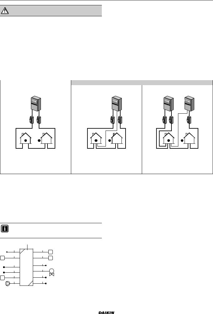
6 Preparation
WARNING
The backup heater should have a dedicated power supply.
6.3.2 About preferential kWh rate power supply
Electricity companies throughout the world work hard to provide reliable electric service at competitive prices and are often authorized to bill clients at benefit rates. E.g. time-of-use rates, seasonal rates, Wärmepumpentarif in Germany and Austria, ...
This equipment allows for connection to such preferential kWh rate power supply delivery systems.
Consult with the electricity company acting as provider at the site where this equipment is to be installed to know whether it is appropriate to connect the equipment in one of the preferential kWh rate power supply delivery systems available, if any.
When the equipment is connected to such preferential kWh rate power supply, the electricity company is allowed to:
interrupt power supply to the equipment for certain periods of time;
demand that the equipment only consumes a limited amount of electricity during certain periods of time.
The indoor unit is designed to receive an input signal by which the unit switches into forced off mode. At that moment, the outdoor unit compressor will not operate.
Whether the power supply is interrupted or not, the wiring to the unit is different.
6.3.3 Overview of electrical connections except external actuators
|
Preferential kWh rate power supply |
|
|
Normal power supply |
Power supply is NOT interrupted |
Power supply is interrupted |
|
a |
b |
a |
b |
3 |
1 |
3 |
4 |
1 |
4 |
1 |
|
2 |
2 |
|
|
|
2 |
|
|
During preferential kWh rate power supply |
During preferential kWh rate power supply |
|||
|
|
activation, power supply is NOT interrupted. |
activation, power supply is interrupted |
|||
|
|
The outdoor unit is turned off by the control. |
immediately or after some time by the |
|||
|
|
Remark: The electricity company must always |
electricity company. In this case, the indoor |
|||
|
|
allow the power consumption of the indoor unit. unit must be powered by a separate normal |
||||
|
|
|
|
|
power supply. |
|
aNormal power supply
bPreferential kWh rate power supply 1 Power supply for outdoor unit
2 Power supply and interconnection cable to indoor unit
3 Power supply for backup heater
4 Preferential kWh rate power supply (voltage free contact)
5 Normal kWh rate power supply (to power the indoor unit PCB in the event of power supply interruption of the preferential kWh rate power supply)
6.3.4Overview of electrical connections for external and internal actuators
The following illustration shows the required field wiring.
INFORMATION
The following illustration is an example and may NOT match your system layout.
|
a |
|
20 |
6 |
|
15 |
12 |
|
13 |
21 |
|
16 |
||
14 |
||
M |
||
17 |
||
14 |
||
18 |
19 |
|
a |
Indoor unit |
Installer reference guide |
EHVH/X16 |
21 |
Daikin Altherma - Low Temperature Split |
4P313777-1 – 2012.05 |
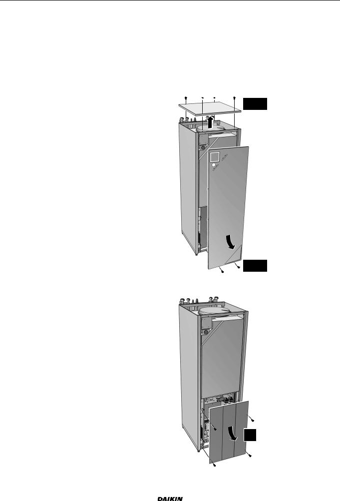
|
|
|
|
Maximum |
|
|
|
|
running |
Item |
Description |
|
Wires |
current |
Outdoor |
unit and indoor unit power supply |
|
||
1 |
Power supply for |
2+GND or |
(a) |
|
|
outdoor unit |
3+GND |
|
|
|
|
|
|
|
2 |
Power supply and |
3 |
|
(c) |
|
interconnection cable |
|
|
|
|
to indoor unit |
|
|
|
|
|
|
|
|
3 |
Power supply for |
See table below. |
— |
|
|
backup heater |
|
|
|
|
|
|
|
|
4 |
Preferential kWh rate |
2 |
|
(d) |
|
power supply (voltage |
|
|
|
|
free contact) |
|
|
|
|
|
|
|
|
5 |
Normal kWh rate power |
2 |
|
6.3 A |
|
supply |
|
|
|
|
|
|
|
|
User interface |
|
|
|
|
6 |
User interface |
2 |
|
(e) |
|
|
|
|
|
Optional |
equipment |
|
|
|
11 |
Power supply for |
2 |
|
(b) |
|
bottom plate heater |
|
|
|
|
|
|
|
|
12 |
Room thermostat |
3 or 4 |
100 mA(b) |
|
13 |
Outdoor ambient |
2 |
|
(b) |
|
temperature sensor |
|
|
|
|
|
|
|
|
14 |
Indoor ambient |
2 |
|
(b) |
|
temperature sensor |
|
|
|
|
|
|
|
|
15 |
Heat pump convector |
4 |
|
100 mA(b) |
Field supplied components |
|
|
|
|
16 |
Shut-off valve |
2 |
|
(b) |
|
|
|
|
|
17 |
Electricity meter |
2 |
(per meter) |
(b) |
|
|
|
|
|
18 |
Domestic hot water |
2 |
|
(b) |
|
pump |
|
|
|
|
|
|
|
|
19 |
Alarm output |
2 |
|
(b) |
|
|
|
|
|
20 |
Changeover to external |
2 |
|
(b) |
|
heat source control |
|
|
|
|
|
|
|
|
21 |
Space cool/heat |
2 |
|
(b) |
|
operation control |
|
|
|
|
|
|
|
|
22 |
Power consumption |
2 |
(per input |
(b) |
|
digital inputs |
signal) |
|
|
|
|
|
|
|
(a)Refer to name plate on outdoor unit.
(b)Minimum cable section 0.75 mm².
(c)Cable section 2.5 mm².
(d)Cable section 0.75 mm² till 1.25 mm²; maximum length: 50 m. Voltage-free contact shall ensure the minimum applicable load of 15 V DC, 10 mA.
(e)Cable section 0.75 mm² till 1.25 mm²; maximum length: 500 m. Applicable for both single user interface and dual use interface connection.
Backup heater |
|
Required number of |
type |
Power supply |
conductors |
*3V |
1x 230 V |
2+GND |
|
|
|
*9W |
1x 230 V |
2+GND + 2 bridges |
|
|
|
|
3x 230 V |
3+GND + 1 bridge |
|
|
|
|
3x 400 V |
4+GND |
|
|
|
7 Installation
7 Installation
7.1Opening the units
7.1.1To open the indoor unit and switch box cover
1Loosen and remove the screws at the bottom of the unit.
2Slide the front panel of the unit downwards and remove it.
3Loosen and remove the 4 screws that fix the top panel.
4Remove the top panel from the unit.
 3
3 
4x 
4
2
1 |
2x |
|
5Loosen and remove the 4 screws that fix the switch box cover.
6Remove the switch box cover.
4x
EHVH/X16 |
Installer reference guide |
Daikin Altherma - Low Temperature Split |
22 |
4P313777-1 – 2012.05 |

7 Installation
7.2Mounting the indoor unit
7.2.1 To install the indoor unit
1 Lift the indoor unit from the pallet and place it on the floor.
3x |
1 |
|
|
2 |
120kg |
2Slide the indoor unit into position.
3Adjust the height of the leveling feet to compensate for floor irregularities. The maximum allowed deviation is 1°.
 ≤1°
≤1°
7.3Connecting the water piping
7.3.1 To connect the water piping
NOTICE
Do NOT use excessive force when connecting the piping. Deformation of the piping can cause malfunctioning of the unit.
To facilitate service and maintenance, 2 shut-off valves are provided. Mount the valves on the water inlet and on the water outlet. Mind their the position. Orientation of the integrated drain and fill valves is important for servicing.
1 Install the shut-off valves on the water pipes.
a c |
d b |
aSpace heating/cooling water out
bSpace heating/cooling water in
cDomestic hot water out
dDomestic cold water in (cold water supply)
NOTICE
It is recommended to install shut-off valves to domestic cold water in and domestic hot water out connections. Shut-off valves are field supplied.
NOTICE
To avoid damage to the surroundings in case of water leakage, it is recommended to close the cold water inlet stop valves during periods of absence.
2Screw the indoor unit nuts on the shut-off valves.
3Connect the domestic hot water in and out pipes to the indoor unit.
NOTICE
A drain device and pressure relief device should be installed on the cold water inlet connection of the domestic hot water cylinder.
To avoid back siphonage, it is recommended to install a non-return valve on the water inlet of the domestic hot water tank in accordance with the applicable legislation.
It is recommended to install a pressure reducing valve on the cold water inlet in accordance with the applicable legislation.
An expansion vessel should be installed on the cold water inlet in accordance with the applicable legislation.
It is recommended to install the pressure relief valve on higher position as top of the domestic hot water tank.
Heating of the domestic hot water tank causes water to expand and without pressure relief valve the water pressure inside the tank can rise above the tank design pressure. Also the field installation (piping, tapping points, etc.) connected to the tank is subjected to this high pressure. To prevent this, a pressure relieve valve needs to be installed.
The overpressure prevention depends on the correct operation of the field installed pressure relief valve. If this is NOT working correctly, overpressure will deform the tank and water leakage may occur. To confirm good operation, regular maintenance is required.
7.3.2To connect the pressure relief valve to the drain
The blow out of the pressure relief valve is coming out of the backside of the unit.
a
a Pressure relief blow-out
The blow out should be connected to an appropriate drain according to the applicable legislation. It is recommended to use a tundish.
Installer reference guide |
EHVH/X16 |
23 |
Daikin Altherma - Low Temperature Split |
4P313777-1 – 2012.05 |
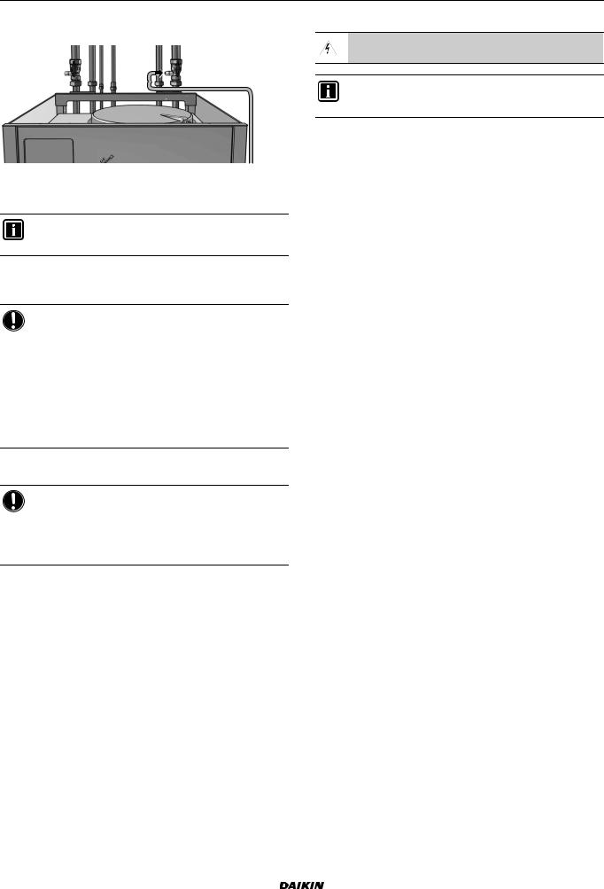
7 Installation
7.3.3 To fill the water circuit
1 Connect the water supply hose to the fill valve.
2Open the fill valve.
3Make sure that the automatic air purge valve is open (at least 2 turns).
INFORMATION
For location of the air purge valve, see Components: Indoor unit.
4Fill the circuit with water until the manometer indicates a pressure of ±2.0 bar.
5Purge as much air as possible from the water circuit.
NOTICE
Air in the water circuit can cause malfunctioning of the backup heater. During filling, it may not be possible to remove all the air from the circuit. Remaining air will be removed through the automatic air purge valves during the initial operating hours of the system. Additional filling with water afterwards may be required.
To purge the system, use the special function as described in To perform an air purge. This function should be used to purge the heat exchanger coil of the domestic hot water tank.
6Close the fill valve.
7Disconnect the water supply hose from the fill valve.
NOTICE
The water pressure indicated on the manometer will vary depending on the water temperature (higher pressure at higher water temperature).
However, at all times water pressure shall remain above 1 bar to avoid air entering the circuit.
7.3.4 To fill the domestic hot water tank
1Open every hot water tap in turn to purge air from the system pipe work.
2Open the cold water supply valve.
3Close all water taps after all air is purged.
4Check for water leaks.
5Manually operate the field installed pressure relief valve to ensure that free water flow through the discharge pipe.
7.3.5 To insulate the water piping
The piping in the complete water circuit must be insulated to prevent condensation during cooling operation and reduction of the heating and cooling capacity.
If the temperature is higher than 30°C and the humidity is higher than RH 80%, the thickness of the sealing materials should be at least 20 mm to prevent condensation on the surface of the sealing.
7.4Connecting the electrical wiring
 DANGER: RISK OF ELECTROCUTION
INFORMATION
More information about the legend and the location of the wiring diagram of the unit can be found in Wiring diagram.
7.4.1 About electrical compliance
Only for ERLQ006CAV3+ERLQ008CAV3 |
|
||
Equipment |
complying |
with |
EN/IEC 61000-3-12 |
(European/International Technical Standard setting the limits for harmonic currents produced by equipment connected to public lowvoltage systems with input current >16 A and ≤75 A per phase.).
Only for indoor units
See To connect the backup heater power supply.
EHVH/X16 |
Installer reference guide |
Daikin Altherma - Low Temperature Split |
24 |
4P313777-1 – 2012.05 |
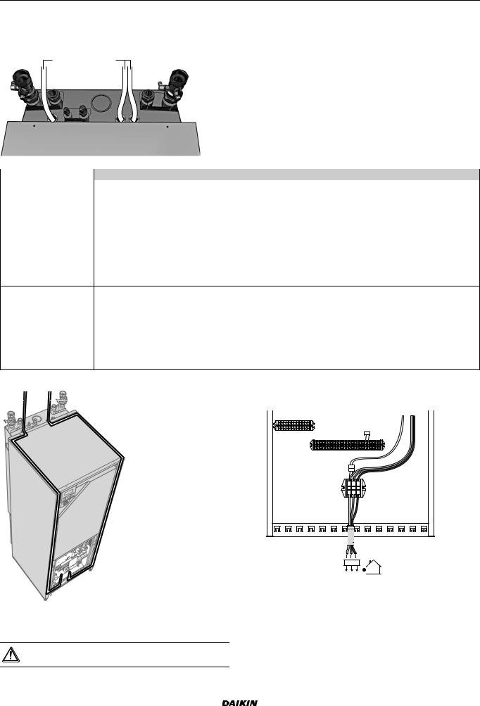
7 Installation
7.4.2To connect the electrical wiring on the indoor unit
1To open the indoor unit, see To open the indoor unit.
2Wiring should enter the unit from the top:
ab+c
Routing |
Possible cables (depending on unit type and installed options) |
a |
User interface |
Low voltage |
Power consumption digital inputs (field supply) |
|
Outdoor ambient temperature sensor (option) |
|
Indoor ambient temperature sensor (option) |
|
Electrical meters (field supply) |
|
|
b |
Interconnection cable |
High voltage power supply |
Normal kWh rate power supply |
Preferential kWh rate power supply
Power supply for backup heater
Power supply for bottom plate heater (option)
c |
|
Preferential power supply contact |
|
High voltage control signal |
Heat pump convector (option) |
|
|
|
|
Room thermostat (option) |
|
|
|
Shut-off valve (field supply) |
|
|
|
Domestic hot water pump (field supply) |
|
|
|
Alarm output |
|
|
|
Changeover to external heat source control |
|
|
|
Space cool/heat operation control |
|
3 |
Routing of the wiring inside the unit should be as follows: |
7.4.3 To connect the main power supply |
|
a |
b+c |
|
1 Connect the main power supply. |
|
In case of normal kWh rate power supply |
||
|
|
|
|
|
|
|
X1A X19A |
|
|
|
X5M |
|
|
|
X2M |
|
|
|
3031 |
X6Y |
X6YA |
X1M |

 a
a
1 2
2 3
3
1 2 3
4Fix the cable with cable ties to the cable tie mountings to ensure strain relief and to make sure that it does NOT come in contact with the piping and sharp edges.
CAUTION
Do NOT push or place redundant cable length in the unit.
Installer reference guide |
EHVH/X16 |
25 |
Daikin Altherma - Low Temperature Split |
4P313777-1 – 2012.05 |
 Loading...