


Daikin EWAQ-E-XL, EWAQ-E-XR, EWAQ-E-XS, EWAQ-F-SL, EWAQ-F-SR User manual
...Installation, Operation and Maintenance Manual
D–EIMAC00804-14EU
Air cooled scroll chiller
EWAQ~E- / EWAQ~F-
SS (Standard Efficiency - Standard Noise)
SL (Standard Efficiency - Low Noise)
SR (Standard Efficiency - Extra Low Noise)
XS (High Efficiency - Standard Noise)
XL (High Efficiency - Low Noise)
XR (High Efficiency - Extra Low Noise)
Cooling capacity from 171 to 675 kW Refrigerant: R410A
English .............. |
9 |
Deutsch............ |
19 |
Français ........... |
29 |
Nederlands....... |
39 |
Español............ |
49 |
Italiano ............ |
59 |
Ελληνικά ......... |
69 |
Português ........ |
79 |
Русский .......... |
89 |
Svenska .......... |
99 |
Norsk ............. |
109 |
Finnish (Suomi) 119 |
|
Polski .............. |
129 |
Čech .............. |
139 |
Hrvat .............. |
149 |
Magyar ........... |
159 |
Român ă ......... |
169 |
Slovensky........ |
179 |
Български ...... |
189 |
Slovenščina..... |
199 |
English language: Original Instructions
All other language: Translation of the Original Instructions
D-EIMAC00804-14EU - 1/209
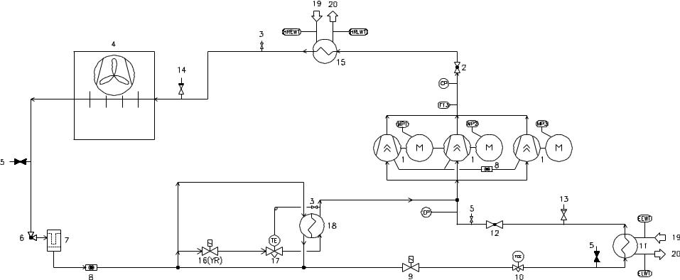
A – Typical refrigerant circuit – The number of compressors and water inlet and outlet are indicative. Please refer to the machine dimensional diagrams for exact water connections.
A – Typischer Kältemittelkreislaufs – Die Anzahl derVerdampfer und Wasserzuund ablauf haben Beispielcharakter. Für die genauen Wasseranschlüsse bitte i n den Zeichnungen zur Maschinebemessung nachsehen.
A – Circuit du réfrigérant typique – Le numéro des compresseurs et des entrées et sorties de l'eau est indicatif. Consulter les schémas de dimensions de la machine pour avoir des indications plus précises sur les connexions de l'eau.
A – Typisch koelcircuit - Het aantal compressors en waterinen uitlaten is indicatief. Raadpleeg de schema's van de machine voor de exacte wateraansluitingen.
A – Circuito de refrigeración típico – El número de los compresores y de las entradas y salidas de agua es indicativo. Por favor, consulte los diagramas de la máquina para conocer las conexiones hidráulica exactas.
A – Circuito del refrigerante tipico – Il numero dei compressori e degli ingressi e uscite dell'acqua è indicativo. Consultare i disegni dimensionali della macchina per indicazioni più precise sulle connessioni dell'acqua.
A – Τυπικό ψυκτικό κύκλωµα – Ο αριθµός των συµπιεστών και το νερό εισόδου και εξόδου είναι ενδεικτικά. Παρακαλώ ανατρέξτε στα διαγράµµατα διαστάσεων του µηχανήµατος για τις ακριβείς συνδέσεις νερού.
A – Circuito do refrigerante típico – O número de co mpressores e de ingressos e saídas da água é indica tivo. Consultar os desenhos dimensionais da máquina para obter indicações mais exatas sobre as conexões da água.
A – Обычный контур хладагента - Количество компрессоров, входов и выходов воды - ориентировочное. Более подробные указания по подключению воды найдёте в чертежах, содержащих размеры машины.
A – Typisk köldmediekretsen - Antalet kompressorer o ch vatten inlopp och utlopp är vägledande. Se maskinens dimensionsritningarna för exakta vattenanslutn ing. A – Typisk kjølekrets – Antall kompressorer, vanninn løp og vannutløp er veiledende. Vennligst referer t il maskinens måldiagrammer for nøyaktige vannkoblin ger.
A – Tyypillinen jäähdytysjärjestelmä – Kompressorienja veden tulojen ja poistojen lukumäärä on osoittava. Viittaa koneen mitoituspiirroksiin vesiliitäntöihin liittyvää yksityiskohtaisempaa tietoa varten.
A – Typowy obwód chłodzenia – Liczba sprężarek oraz wlotu i wylotu wody są wskazujące. Co do dokładnych połączeń wody prosimy odnieść się do schematów wymiarowych urządzenia.
A – Typický chladící okruh - Po čet kompresorů a vodních vstupů a výstup ů je orientační. Konzultujte rozměrové výkresy stroje pro přesnější informace o vodovodních přípojkách. A – Tipičan rashladni krug – Broj kompresora i ulaza i izlaza za vodu su samo indikativni. Molimo vas pogledajte dijagrame o dimenzijama stroja radi što točnijeg položaja priključaka za vodu.
A – Tipikus hűtőkör – A kompresszorok és a víz bemeneti és kimeneti csatlakozási pontjainak száma meghatározó. A ponto s vízcsatlakozási jellemz őkért kérjük, tekintse meg a gép jellemzőit tartalmazó diagramokat.
A – Circuit de răcire caracteristic – Numărul compresoarelor şi al punctelor de intrare şi ieşire a apei sunt indicative. Vă rugăm consultaţi diagramele dimensionale ale maşinii pentru determinarea conexiunilor exacte pentru apă.
A – Typický chladiaci okruh – Po čet kompresorov a vodných vstupov a výstupov je orie ntačný. Konzultujte rozmerové výkresy stroja pre presne jšie informácie o vodných prípojkách.
A – Типична схема за охлаждане – Броят на компресорите и водните входове и изходи са примерни. Моля направете справка, с диаграмата с размерите на машината, за точния брой на водните връзки.
A – Značilni krogotok hladilnega sredstva. Število kompresorjev in dovodov ter odvodov za vodo je okvirno. Priključki za vodo so natančneje prikazani na merskih risbah naprave.
D-EIMAC00804-14EU - 2/209

A
D-EIMAC00804-14EU - 3/209
B – Typical refrigerant circuit with heat recovery – The number of compressors and water inlet and outlet are indicative. Please refer to the machine dimensional diagrams for exact water connections.
B – Typischer Kältemittelkreislaufs Wärmerückgewinnung – Die Anzahl der Verdampfer und Wasserzuund ablauf haben Beispielcharakter. Für die genauen Wasse ranschlüsse bitte in den Zeichnungen zur Maschinebemessung nachsehen.
B – Circuit du réfrigérant typique avec dispositif de récupération de la chaleur – Le numéro des compresseurs et des entrées et sorties de l'eau est indicatif. Consulter les schémas de dimensions de la machine pour avoir des indications plus précises sur les connexions de l'eau.
B – Typisch koelcircuit met warmteterugwinning - Het aantal compressors en waterinen uitlaten is indicatief. Raadpleeg de schema's van de machine voor de exacte wateraansluitingen.
B – Circuito de refrigeración típico con recuperación de calor – El número de los compresores y de las entradas y salidas de agua es indicativo. Por favor, consulte los diagramas de la máquina para conocer las conexiones hidráulic a exactas.
B – Circuito del refrigerante tipico con dispositivo di recupero del calore – Il numero dei compressori e degli ingressi e uscite dell'acqua è indicativo. Consultare i disegni dimensionali della macchina per indicazioni più pre cise sulle connessioni dell'acqua.
Β – Τυπικό ψυκτικό κύκλωµα µε ανάκτηση θερµότητας – Ο αριθµός των συµπιεστών και το νερό εισόδου και εξόδου είναι ενδεικτικά. Παρακαλώ ανατρέξτε στα διαγράµµατα διαστάσεων του µηχανήµατος για τις ακριβείς συνδέσεις νερού.
B – Circuito do refrigerante típico com dispositivo de recuperação do calor - O número dos compressores e dos ingressos e saídas da água é indicativo. Con sultar os desenhos dimensionais da máquina para indicações mais exatas sobre as conexões da água.
B – Обычный контур хладагента с устройством для утилизации теплоты - Количество компрессоров, входов и выходов воды - ориентировочное. Более подробные указания по подключению воды найдёте в чертежах, содержащих размеры машины.
B – Typisk köldmediekretsen med värmeåtervinning - Antalet kompressorer och vatten inlopp och utlopp ärvägledande. Se maskinens dimensionella diagram för exakta vattenanslutningar.
B – Typisk kjølekrets med varmegjenvinning – Antall kompressorer, vanninnløp og vannutløp er veiledende . Vennligst referer til maskinens måldiagrammer for nøyaktige vannkoblinger.
B – Tyypillinen jäähdytysjärjestelmä lämmön talteenotolla – Kompressorien ja veden tulojen ja poistojen lukumäärä on osoittava. Viittaa koneen mitoituspiirroksiin vesiliitäntöihin liittyvää yksityiskohtaisempaa tietoa varten.
B – Typowy obwód chłodzenia z odzyskiwaniem ciepła –Liczba sprężarek oraz wlotu i wylotu wody są wskazujące. Co do dokładnych połączeń wody prosimy odnieść się do schematów wymiarowych urządzenia.
B – Typický chladící okruhse za řízením na rekuperaci tepla - Počet kompresorů a vodních vstupů a výstup ů je orientační. Konzultujte rozměrové výkresy stroje pro přesnější informace o vodovodních přípojkách.
B – Tipičan rashladni krug s povratom topline – Broj kompresora i ulaza i izlaza za vodu su samo indikativni. Molimo vas pogledajte dijagrame o dimenzijama stroja radi što točnijeg položaja priklju čaka za vodu.
B – Tipikus hűtőkör h ővisszanyerővel– A kompresszorok és a víz bemeneti és kimeneticsatlakozási pontjainak száma meghatározó. A pontos vízcsatlakozási jellemz őkért kérjük, tekintse meg a gép jellemzőit tartalmazó diagramokat.
B – Circuit de răcire cu recuperare de căldură caracteristic – Numărul compresoarelor şi al punctelor de intrare şi ieşire a apei sunt indicative. Consultaţi diagramele dimensionale ale maşinii pentru identificarea exactă a conexiunilor de apă.
B – Typický chladiaci okruh so zariadením na rekuper áciu tepla – Po čet kompresorov a vodných vstupov a výstupov je orie ntačný. Konzultujte rozmerové výkresy stroja pre presnejšie informácie o vodných prípojkách.
B – Типична схема за охлаждане с използване на топлина – Броят на компресорите и водните входове и изходи са примерни. Моля направете справка, с диаграмата с размерите на машината, за точния брой на водните връзки.
B – Značilni krogotok hladilnega sredstva z rekuperacijo toplote. Število kompresorjev in dovodov ter odvodov za vodo je okvirno. Priključki za vodo so natančneje prikazani na merskih risbah naprave.
B
D-EIMAC00804-14EU - 4/209
D-EIMAC00804-14EU - 5/209
|
ENGLISH |
DEUTSCH |
FRANÇAIS |
NEDERLANDS |
ESPAÑOL |
|
ITALIANO |
ΕΛΛΗΝΙΚΑ |
|
1 |
Compressor |
Verdichter |
Compresseur |
Compressor |
Compresor |
|
Compressore |
Συµπιεστής |
|
2 |
Discharge shut off valve |
Absperrventil Druckleitung |
Robinet d'évacuation |
Afvoerklep |
Válvula de cierre de descarga |
|
Rubinetto di scarico |
Εκφόρτωση βαλβίδας κλεισίµατος |
|
3 |
¼ SAE Flare Valve |
¼ SAE Flare Ventil |
Vanne ¼ SAE Fl are |
¼ SAE Opruimklep |
Válvula ¼ SAE Flare |
|
Valvola ¼ |
SAE Flare |
¼ SAE Φωτοβολίδα βαλβίδας |
4 |
Condenser coil and Axial |
Verflüssigerregister und |
Batterie à condensation et |
Condensatorwikkeling en Axiale |
Serpentín del condensador y |
|
Batteria condensante e |
Πηνίο συµπυκνωτή και Αξονικός |
|
ventilator |
Axialventilator |
ventilateur axial |
ventilator |
Ventilador axial |
|
ventilatore assiale |
ανεµιστήρας |
||
|
|
||||||||
5 |
Service port |
Betriebsanschluss |
Port de maintenance |
Dienstpoort |
Abertura de servicio |
|
Portello per assistenza |
Υπηρεσία θύρας |
|
6 |
Liquid line isolating valve |
Selbstschlussventil |
Vanne d'isolement de la ligne du |
Afsluitklep vloeistoflijn |
Válvula de aislamiento de la línea |
|
Valvola isolante linea del liquido |
Γραµµή υγρού βαλβίδας |
|
Flüssigkeitsleitung |
liquide |
del líquido |
|
αποµόνωσης |
|||||
|
|
|
|
|
|
||||
7 |
Dehydration filter |
Entwässerungsfilter |
Filtre déshydrateur |
Dehydratatiefilter |
Filtro deshidratador |
|
Filtro deidratatore |
Φίλτρο αφυδάτωσης |
|
8 |
Liquid and humidity indicator |
Flüssigkeitsund |
Indicateur de liquide et humidité |
Indictaor vloeistof en vochtigheid |
Indicador de líquido y humedad |
|
Indicatore di liquido e umidità |
Υγρό και δείκτης υγρασίας |
|
Feuchtigkeitsanzeiger |
|
||||||||
|
|
|
|
|
|
|
|
|
|
9 |
Solenoid valve |
Solenoidventil |
Vanne solénoïde |
Elektromagnetische klep |
Válvula solenoide |
|
Valvola s olenoide |
Ηλεκτροµαγνητική βαλβίδα |
|
10 |
Electronic expansion valve |
Elektronisches Expansionsventil |
Détendeur électronique |
Elektronische expansieklep |
Válvula de expansión electrónica |
|
Valvola di espansione elettronica |
Ηλεκτρονική βαλβίδα εκτόνωσης |
|
11 |
Evaporator |
Verdampfer |
Evaporateur |
Verdamper |
Evaporador |
|
Evaporatore |
Εξατµιστής |
|
12 |
Suction shut off valve |
Absperrventil Ansaugleitung |
Robinet d'aspiration |
Afsluitklep aanzuiging |
Válvula de cierre aspiración |
|
Rubinetto di aspirazione |
Αναρρόφηση βαλβίδας κλεισίµατος |
|
13 |
Low-pressure safety valve |
Niederdruck-Sicherheitsventil |
Soupape de sécurité à basse |
Veiligheidsklep lage druk |
Válvula de seguridad de baja |
|
Valvola di sicurezza a bassa |
Χαµηλή-πίεση βαλβίδας ασφαλείας |
|
pression |
presión |
|
pressione |
|
|||||
|
|
|
|
|
|
|
|||
14 |
High-pressure safety valve |
Hochdruck-Sicherheitsventil |
Soupape de sécurité haute |
Veiligheidsklep hoge druk |
Válvula de seguridad de alta |
|
Valvola di sicurezza alta |
Υψηλή-πίεση βαλβίδας ασφαλείας |
|
pression |
presión |
|
pressione |
|
|||||
|
|
|
|
|
|
|
|||
15 |
Heat recovery (optional) |
Wärmerückgewinnung (optional) |
Dispositif de récupération de la |
Inrichting voor warmteterugwinning |
Recuperador de calor (opcional) |
|
Dispositivo di recupero del |
Ανάκτηση θερµότητας (προαιρετικό) |
|
chaleur (en option) |
(optie) |
|
calore (opzionale) |
||||||
|
|
|
|
|
|
||||
|
Heat recovery solenoid valve |
Solenoidventil |
Vanne solénoïde de récupération |
Elektomagnetische klep |
Válvula solenoide del recuperador |
|
Valvola solenoide recupero del |
Ανάκτηση θερµότητας |
|
16 (YR) |
Wärmerückgewinnung (nur für |
de la chaleur (seulement dans la |
warmteterugwinning |
|
ηλεκτροµαγνητικής βαλβίδας (µόνο |
||||
(only for total heat recovery |
de calor (sólo para versión con |
|
calore (solo nella versione a |
||||||
Version mit totaler |
version à récupération totale de la |
(alleen voor versie met totale |
|
για την έκδοση συνολικής |
|||||
|
version) |
recuperador de calor total) |
|
recupero totale del calore) |
|||||
|
Wärmerückgewinnung) |
chaleur) |
warmteterugwinning) |
|
ανάκτησης θερµότητας) |
||||
|
|
|
|
|
|
||||
|
Heat recovery thermostatic |
Wärmerückgewinnung |
Détendeur thermostatique du |
Thermostatische expansieklep |
Válvula de expansión termostática |
|
Valvola di espansione |
Θερµοστατική ανάκτηση θερµότητας |
|
|
|
termostatica dispositivo di |
|||||||
17 |
expansion valve |
thermostatische Expansionsventil |
dispositif de récupération de la |
warmteterugwinning |
del recuperador de calor (sólo para |
|
βαλβίδας εκτόνωσης (µόνο για την |
||
|
recupero del calore (solo nella |
||||||||
(only for total heat recovery |
(nur für Version mit totaler |
chaleur (seulement dans la version |
(alleen voor versie met totale |
versión con recuperador de calor |
|
έκδοση συνολικής ανάκτησης |
|||
|
|
versione a recupero totale del |
|||||||
|
version) |
Wärmerückgewinnung) |
à récupération totale de la chaleur) |
warmteterugwinning) |
total) |
|
θερµότητας) |
||
|
|
calore) |
|
||||||
|
|
|
|
|
|
|
|
|
|
18 |
Subcooler (only for total heat |
Unterkühler (nur für Version mit |
Sous-refroidisseur seulement dans |
Nakoeler (alleen voor versie met |
Subenfriador (sólo para versión |
|
Sottoraffreddatore (solo nella |
Υποψύκτης (µόνο για την έκδοση |
|
la version à récupération totale de |
|
versione a recupero totale del |
|||||||
recovery version) |
totaler Wärmerückgewinnung) |
totale warmteterugwinning) |
con recuperador de calor total) |
|
συνολικής ανάκτησης θερµότητας) |
||||
|
la chaleur) |
|
calore) |
|
|||||
|
|
|
|
|
|
|
|
||
19 |
Water inlet connection |
Wasserzulaufanschluss |
Connexion entrée eau |
Aansluiting waterinlaat |
Conexión deentrada de agua |
|
Connessione ingresso acqua |
Σύνδεση νερού εισόδου |
|
20 |
Water outlet connection |
Wasserablaufanschluss |
Connexion sortie eau |
Aansluiting wateruitlaat |
Conexión de salida de agua |
|
Connessione uscita acqua |
Σύνδεση νερού εξόδου |
|
EP |
Low-pressure transducer |
Niederdruckwandler |
Transducteur basse pression |
Transductor lage druk |
Transductor de baja presión |
|
Trasduttore bassa pressione |
Χαµηλής-πίεσης µετατροπέας |
|
CP |
High-pressure transducer |
Hochdruckwandler |
Transducteur haute pression |
Transductor hoge druk |
Transductor de alta presión |
|
Trasduttore alta pressione |
Υψηλής-πίεσης µετατροπέας |
|
F13 |
High-pressure switch |
Maximum-Druckwächter |
Pressosta de haute pression |
Hogedrukschakelaar |
Interruptor de alta presión |
|
Pressostato di alta |
∆ιακόπτης υψηλής πίεσης |
|
MP1 |
Motor thermistor compressor 1 |
Motorthermistor Verdichter 1 |
Compresseur thermistance moteur |
Motor thermistor compressor 1 |
Termistor del motor del compresor |
|
Compressore termistore motore |
Κινητήρας θερµοστάτη συµπιεστή 1 |
|
1 |
1 |
|
1 |
|
|||||
|
|
|
|
|
|
|
|||
MP2 |
Motor thermistor compressor 2 |
Motorthermistor Verdichter 2 |
Compresseur thermistance moteur |
Motor thermistor compressor 2 |
Termistor del motor del compresor |
|
Compressore termistore motore |
Κινητήρας θερµοστάτη συµπιεστή 2 |
|
2 |
2 |
|
2 |
|
|||||
|
|
|
|
|
|
|
|||
MP3 |
Motor thermistor compressor 3 |
Motorthermistor Verdichter 3 |
Compresseur thermistance moteur |
Motor thermistor compressor 3 |
Termistor del motor del compresor |
|
Compressore termistore motore |
Κινητήρας θερµοστάτη συµπιεστή 3 |
|
3 |
3 |
|
3 |
|
|||||
|
|
|
|
|
|
|
|||
EEWT |
Evaporator Entering Water |
Temperaturfühler Wasserzulauf |
Sonde de température de l'eau de |
Temperatuursonde |
Sonda temperatura del agua en |
|
Sonda temperatura acqua |
Εξατµιστής Εισερχόµενου Νερού |
|
Temperature probe |
Verdampfer |
l'évaporateur en entrée |
binnenstromend water verdamper |
entrada en el evaporador |
|
evaporatore in ingresso |
Θερµοκρασίας αισθητήρα |
||
|
|
||||||||
ELWT |
Evaporator Leaving Water |
Temperaturfühler Wasserablauf |
Sonde de température de l'eau de |
Temperatuursonde uitstromend |
Sonda temperatura del agua en |
|
Sonda temperatura acqua |
Εξατµιστής Εξερχόµενου Νερού |
|
Temperature probe |
Verdampfer |
l'évaporateur en sortie |
water verdamper |
salida del evaporador |
|
evaporatore in uscita |
Θερµοκρασίας αισθητήρα |
||
|
|
||||||||
|
|
Temperaturfühler Wasserzulauf |
Sonde de température de l'entrée |
Temperatuursonde |
Sonda temperatura del agua en |
|
Sonda temperatura ingresso |
Ανάκτηση Θερµότητας Εισόδου |
|
|
Heat Recovery Entering Water |
binnenstromend water |
|
||||||
HREWT |
Wärmerückgewinnung (nur für |
d'eau de récupération de chaleur |
entrada en el recuperador de calor |
|
acqua recupero di calore (solo |
Νερού θερµοκρασίας αισθητήρα |
|||
Temperature probe (only for total |
warmteterugwinning |
|
|||||||
Version mit totaler |
(seulement dans la version à |
(sólo para versión con recuperador |
|
nella versione a recupero totale |
(µόνο για την έκδοση συνολικής |
||||
|
heat recovery version) |
(alleen voor versie met totale |
|
||||||
|
Wärmerückgewinnung) |
récupération totale de la chaleur) |
de calor total) |
|
del calore) |
|
ανάκτησης θερµότητας) |
||
|
|
warmteterugwinning) |
|
|
|||||
|
|
|
|
|
|
|
|
|
|
|
Heat Recovery Leaving Water |
Temperaturfühler Wasserablauf |
Sonde de température de la sortie |
Temperatuursonde uitstromend |
Sonda temperatura del agua en |
|
Sonda temperatura uscita acqua |
Ανάκτηση Θερµότητας Εξερχόµενου |
|
HRLWT |
Temperature probe |
Wärmerückgewinnung (nur für |
d'eau de récupération de chaleur |
water warmteterugwinning |
salida del recuperador de calor |
|
recupero di calore (solo nella |
Νερού θερµοκρασίας αισθητήρα |
|
(only for total heat recovery |
Version mit totaler |
(seulement dans la version à |
(alleen voor versie met totale |
(sólo para versión con recuperador |
|
versione a recupero totale del |
(µόνο για την έκδοση συνολικής |
||
|
|
||||||||
|
version) |
Wärmerückgewinnung) |
récupération totale de la chaleur) |
warmteterugwinning) |
de calor total) |
|
calore) |
|
ανάκτησης θερµότητας) |
|
|
|
|
|
|
|
|
|
|
|
PORTUGUÊS |
РУССКИЙ |
SVENSKA |
NORSK |
SUOMI |
|
POLSKI |
ČESKY |
|
D-EIMAC00804-14EU - 6/209

1 |
Compressor |
Компрессор |
Kompressorn |
Kompressor |
Kompressori |
Sprężarka |
Kompresor |
|
2 |
Torneira de descarga |
Сливнойкран |
Urladda avstängningsventil |
avstengningsventil utløp |
Poiston sulkuventtiili |
Wypływowy zawór odcinający |
Vypouštěcí kohout |
|
3 |
Válvula ¼ SAE Flare |
Клапан¼SAEFlare |
¼ SAE Utflytning ventil |
¼ SAE Fakkelve ntil |
¼ SAE Flare-venttiili |
Zawór sto żkowy ¼ SAE |
Ventil ¼ SAE Flare |
|
4 |
Bateria condensadora e ventilador |
Змеевикконденсатораиосевой |
Kondensor spole och Axiell fläkt |
Kondensatorbatteri og |
Lauhduttimen kierukka ja |
Wężownica skraplacza i |
Kondenzační baterie a axiální |
|
axial |
вентилятор |
Aksialventilator |
aksiaalinen puhallin |
Wentylator osiowy |
ventilátor |
|||
|
|
|||||||
5 |
Portinhola para assistência |
Сервиснаядверца |
Serviceporten |
Serviceluke |
Huoltoaukko |
Port serwisowy |
Služební dví řka |
|
6 |
Válvula isolante linha do líquido |
Изолирующийклапанконтура |
Vätskeledningen isolering ventil |
Avstengningsventilpå flytende linje |
Nestelinjan sulkuventtiili |
Zawóroddzielający linii płynu |
Ventil na izolaci kapalní linky |
|
жидкости |
||||||||
|
|
|
|
|
|
|
||
7 |
Filtro desidratador |
Фильтрводоотделитель |
Dehydratisering filtret |
Avfuktningsfilter |
Kuivatussuodatin |
Filtr odwadniacz |
Sušící filtr |
|
8 |
Indicador de líquido e humidade |
Указательжидкостиивлажности |
Flytande och fuktighets indikator |
Væskeog fuktig hetsindikator |
Nesteja kosteusmittari |
Wskaźnik płynu i wilgotności |
Ukazatel kapaliny a vlhkosti |
|
9 |
Válvula solenóide |
Соленоидныйклапан |
Solenoiden ventil |
Magnetventil |
Solenoidiventtiili |
Zawór elektromagnetyczny |
Solenoidní ventil |
|
10 |
Válvula de expansão eletrónica |
Электронныйрасширительный |
Electronisk expansionsventil |
Elektronisk ekspansjonsventil |
Elektroninen paisuntaventtiili |
Elektroniczny zawór rozprężny |
Elektronický expanzní ventil |
|
клапан |
||||||||
|
|
|
|
|
|
|
||
11 |
Evaporador |
Испаритель |
Förångaren |
Evaporator |
Haihdutin |
Parownik |
Výparník |
|
12 |
Torneira de aspiração |
Всасывающийкран |
Sugning avstängningsventil |
Avstengningsventil innløp |
Imun sulkuventtiili |
Ssawny zawór odcinaj ący |
Sací kohout |
|
13 |
Válvula de segurança de baixa |
Предохранительныйклапан |
Lågt trick säkerhets ventil |
Sikkerhetsventil for lavtrykk |
Alhaisen paineen varoventtiili |
Zawór bezpieczeństwa niskiego |
Pojistný ventil nízkého tlaku |
|
pressão |
низкогодавления |
ciśnienia |
||||||
|
|
|
|
|
||||
14 |
Válvula de segurança de alta |
Предохранительныйклапан |
Högt tryck säkerhets ventil |
Sikkerhetsventil for høytrykk |
Korkean paineen varoventtiili |
Zawór bezpieczeństwa |
Pojistný ventil vysokého tlaku |
|
pressão |
высокогодавления |
wysokiego ciśnienia |
||||||
|
|
|
|
|
||||
15 |
Dispositivo de recuperação do calor |
Устройстводляутилизации |
Värmeåtervinning (tillval) |
Varmegjenvinning (tillegsutstyr) |
Lämmön talteenotto (lisävaruste) |
Odzyskiwanie ciepła (opcja) |
Zařízení na rekuperaci tepla |
|
(opcional) |
теплоты(позапросу) |
(volitelný prvek) |
||||||
|
|
|
|
|
||||
|
Válvula solenóide recuperação do |
Соленоидныйклапанутилизации |
Värmeåtervinning |
Magnetventil varmegjenvinning |
Lämmön talteenoton |
Zawór elektromagnetyczny |
Solenoidní ventil na rekuperaci tepla |
|
16 (YR) |
calor |
solenoidiventtiili (vain versiossa, |
odzyskiwania ciepła (tylko w |
|||||
тепла(толькодляверсииполной |
magnetventil(endast för total |
(kun for utgave total |
(pouze u verzi s kompletní |
|||||
(somente na versão de recuperação |
jossa lämpö otetaan kokonaan |
wersji całkowitego odzyskania |
||||||
|
утилизациитепла) |
värmeåtervinning version) |
varmegjenvinning) |
rekuperací tepla) |
||||
|
total do calor) |
talteen) |
ciepła) |
|||||
|
|
|
|
|
||||
|
Válvula de expansão termostática |
Термостатический |
|
|
Lämmön talteenoton |
Termostatyczny zawór rozprężny |
|
|
|
расширительныйклапан |
Värmeåtervinning termostatisk |
Termostatisk ekspansjonsventil |
Expanzní termostatický ventil |
||||
17 |
dispositivo de recuperação do calor |
termostaattinen paisuntaventtiili |
odzyskiwania ciepła (tylko w |
|||||
устройствадляутилизациитеплоты |
espansionsventil(endast för total |
varmegjenvinning (kun for utgave |
zařízení na rekuperaci tepla (pouze |
|||||
(somente na versão de recuperação |
(vain versiossa, jossa lämpö |
wersji całkowitego odzyskania |
||||||
|
(толькодляверсииполной |
värmeåtervinning version) |
total varmegjenvinning) |
u verzi s kompletní rekuperací tepla) |
||||
|
total do calor) |
otetaan kokonaan talteen) |
ciepła) |
|||||
|
утилизациитепла) |
|
|
|
||||
|
|
|
|
|
|
|
||
18 |
Sub arrefecedor (somente na versão |
Переохладитель |
Underkylare (endast för total |
Underkjøler (kun for utgave total |
Alijäähdytin (vain versiossa, jossa |
Dochładzacz (tylko w wersji |
Podchlazovač (pouze u verzi s |
|
(толькодляверсииполной |
||||||||
de recuperação total do calor) |
värmeåtervinning version) |
varmegjenvinning) |
lämpö otetaan kokonaan talteen) |
całkowitego odzyskania ciepła) |
kompletní rekuperací tepla) |
|||
|
утилизациитепла) |
|||||||
|
|
|
|
|
|
|
||
19 |
Conexão entrada água |
Подсоединениевходаводы |
Vatteninloppsanslutning |
Forbindelse for vanninnløp |
Veden tuloliitäntä |
Połączenie wlotowe wody |
Připojení vstupu vody |
|
20 |
Conexão saída água |
Подсоединениевыходаводы |
Vatten utlopp |
Forbindelse for vannutløp |
Veden pois toliitäntä |
Połączenie wylotowe wody |
Připojení výstupu vody |
|
EP |
Transdutor baixa pressão |
Преобразовательнизкогодавления |
Låg-tryck-omvandlaren |
Lavtrykksomformer |
Alhaisen paineen anturi |
Przetwornik niskiego ciśnienia |
Transduktor nízkého tlaku |
|
CP |
Transdutor alta pressão |
Преобразовательвысокого |
Hög-tryck-givare |
Høytrykksomformer |
Korkeapaineantur i |
Przetwornik wysokiego ciśnienia |
Transduktor vysokého tlaku |
|
давления |
||||||||
|
|
|
|
|
|
|
||
F13 |
Pressóstato de alta |
Релевысокогодавления |
Högtryckvakt |
Høytrykksbryter |
Korkeapaine kytkin |
Pr esostat wysokiego ciśnienia |
Presostat vysokého tlaku |
|
MP1 |
Compressor termistor motor 1 |
Компрессортермистордвигатель1 |
Motortermistor kompressor 1 |
Motor termistor kompressor 1 |
Moottorin termistori kompressori 1 |
Termistor silnika sprężarki 1 |
Kompresor motoru termistoru 1 |
|
MP2 |
Compressor termistor motor 2 |
Компрессортермистордвигатель2 |
Motortermistor kompressor 2 |
Motor termistor kompressor 2 |
Moottorin termistori kompressori 2 |
Termistor silnika sprężarki 2 |
Kompresor motoru termistoru 2 |
|
MP3 |
Compressor termistor motor 3 |
Компрессортермистордвигатель3 |
Motortermistor kompressor 3 |
Motor termistor kompressor 3 |
Moottorin termistori kompressori 3 |
Termistor silnika sprężarki 3 |
Kompresor motoru termistoru 3 |
|
EEWT |
Sonda de temperatura da água do |
Датчиктемпературыводы |
Förångare ingående |
Temperaturføler Innløpsvann |
Haihduttimen sisäänmenevän |
Sonda Wejściowej Temperatury |
Čidlo teploty vody na vstupu |
|
evaporador em entrada |
испарителянавходе |
vattentemperatur sond |
Evaporator |
veden lämpötila-anturi |
Wody Parownika |
výparníku |
||
|
||||||||
ELWT |
Sonda de temperatura da água do |
Датчиктемпературыводы |
Utgående köldbärartemperatur |
Temperaturføler Utløpsvann |
Haihduttimen poistuvan veden |
Sonda Wyjściowej Temperatury |
Čidlo teploty vody na výstupu |
|
evaporador em saída |
испарителянавыходе |
sond |
Evaporator |
lämpötila-anturi |
Wody Parownika |
výparníku |
||
|
||||||||
|
Sonda de temperatura de ingresso |
Датчиктемпературыводынавходе |
Värme Återvinning Ange |
Temperaturføler for |
Lämmön talteenotto |
Sonda Wejściowej Temperatury |
Čidlo teploty vody na vstupu zařízení |
|
HREWT |
da água de recuperação do calor |
устройствадляутилизациитеплоты |
Varmegjenvinning Vanninnløp |
sisäänmenevän veden lämpötila- |
Wody Odzyskiwania Ciepła |
|||
Vattentemperatur sond (endast för |
na rekuperaci tepla (pouze u verzi s |
|||||||
(somente na versão de recuperação |
(толькодляверсииполной |
(kun for utgave total |
anturi (vain versiossa, jossa lämpö |
(tylko w wersji całkowitego |
||||
|
total värmeåtervinning version) |
kompletní rekuperací tepla) |
||||||
|
total do calor) |
утилизациитепла) |
varmegjenvinning) |
otetaan kokonaan talteen) |
odzyskania ciepła) |
|||
|
|
|
||||||
|
Sonda de temperatura de ingresso |
Датчиктемпературыводына |
Värme Återvinning Lämna |
Temperaturføler for |
Lämmön talteenotto poistuvan |
Sonda Wyjściowej Temperatury |
Čidlo teploty vody na vstupu zařízení |
|
HRLWT |
da água de recuperação do calor |
выходеустройствадляутилизации |
Varmegjenvinning Vannutløp |
veden lämpötila-anturi (vain |
Wody Odzyskiwania Ciepła |
na rekuperaci tepla |
||
Vattentemperatur sond (endast för |
||||||||
(somente na versão de recuperação |
теплоты(толькодляверсииполной |
(kun for utgave total |
versiossa, jossa lämpö otetaan |
(tylko w wersji całkowitego |
(pouze u verzi s kompletní |
|||
|
total värmeåtervinning version) |
|||||||
|
total do calor) |
утилизациитепла) |
varmegjenvinning) |
kokonaan talteen) |
odzyskania ciepła) |
rekuperací tepla) |
||
|
|
D-EIMAC00804-14EU - 7/209
|
HRVATSKI |
MAGYAR |
|
ROMÂNĂ |
SLOVENSKY |
БЪЛГАРСКИ |
SLOVENŠČINA |
|
1 |
Kompresor |
Kompresszor |
|
Compresor |
|
Compressore |
Компресор |
Kompresor |
2 |
Ventil za pražnjenje |
Leereszt ő elzáró szelep |
|
Robinet de evacuare |
Vypúš ťací kohútik |
Кран за подаване |
Zaporni ventil izpusta |
|
3 |
¼ SAE Flare Ventil |
¼ SAE Kúpos szelep |
¼ |
SAE Valv |
ă conică |
Ventil ¼ SAE Flare |
Клапан ¼ SAE Flare |
Ventil s priklju čkom SAE Flare ¼ |
4 |
Zavojnica kondenzatora i Aksijalni |
Hőcserélő lemezelt csőkígyó és |
|
Baterie de condensare şi Ventilator |
Kondenzačná batéria a axiálny |
Кондензираща батерия и |
Navitje kondenzatorja in osni |
|
ventilator |
Axiál ventilátor |
|
axial |
|
ventilátor |
вентилатор за извеждане |
ventilator |
|
|
|
|
||||||
5 |
Vrata za servisiranje |
Szerviz port |
|
Uşă pentru asistenţă |
Služobné dvierka |
Обслужващ люк |
Servisna odprtina |
|
6 |
Izolacijski ventil linije za tekućinu |
Folyadék vezeték elzáró szelep |
|
Valvă izolare linie de lichid |
Ventil na izoláciu kvapaln ej linky |
Изолиращ клапан линия на |
Ločilni ventil cevi za tekočine |
|
|
течността |
|||||||
|
|
|
|
|
|
|
|
|
7 |
Dehidratacijski filter |
Vízleválasztó szűrő |
|
Filtru deshidrator |
Sušiaci filter |
Дехидрaтиращ филтър |
Filter za osušitev |
|
8 |
Indikator vlažnosti i teku ćine |
Folyadék és páratartalom jelző |
|
Indicator de lichid şi umiditate |
Ukazovateľ kvapaliny a vlhkosti |
Индикатор за течност и влажност |
Kazalnik tekočin in vlage |
|
9 |
Električni ventil |
Szolenoid szelep |
|
Valvă solenoidă |
Solenoidný ventil |
Клапан зареждане |
Elektromagnetni ventil |
|
10 |
Ventil za elektronsku ekspanziju |
Elektromos tágulás i szelep |
|
Valvă electronică de expansiune |
Expanzný elektronický ventil |
Електронен разширителен клапан |
Elektronski ekspanzijski ventil |
|
11 |
Isparivač |
Párologtató |
|
Evaporator |
|
Výparník |
Изпарител |
Evaporator |
12 |
Usisni ventil |
Szívó oldali elzáró szelep |
|
Robinet de aspiraţie |
Sací kohútik |
Кран за засмукване |
Zaporni ventil za sesanje |
|
13 |
Sigurnosni ventil niskog tlaka |
Biztonsági szelep elégtelen nyomás |
|
Valvă de siguranţă joasă presiune |
Poistný ventil nízkeho tlaku |
Предпазен клапан за ниско налягане |
Nizkotlačni varnostni ventil |
|
elkerülésére |
|
|||||||
|
|
|
|
|
|
|
|
|
14 |
Sigurnosni ventil visokog tlaka |
Biztonsági lefúvató szelep |
|
Valvă de siguranţă înaltă presiune |
Poistný ventil vysokého tlaku |
Предпазен клапан за високо |
Visokotlačni varnostni ventil |
|
|
налягане |
|||||||
|
|
|
|
|
|
|
|
|
15 |
Povrat topline (opcionalno) |
Hővisszanyerő (opciós) |
|
Recuperare de căldură (opţional) |
Zariadenie na rekuperáciu tepla |
Топлообменник (опция) |
Rekuperacija toplote (dodatna |
|
|
(voliteľný prvok) |
možnost) |
||||||
|
|
|
|
|
|
|
||
|
Elektromagnetski ventil za povrat |
Hővisszanyerő szolenoid szelep |
|
Valvă solenoidă recuperare de |
Solenoidný ventil na rekuperáciu |
Топлообменник клапан зареждане |
Elektromagnetni ventil za |
|
16 (YR) |
|
rekuperacijo toplote (samo pri |
||||||
topline (isključivo za verziju totalnog |
(csak teljes hővisszanyerő egység |
|
căldură (numai pentru versiunea cu |
tepla (iba vo verzii s kompletnou |
(само при моделите с пълна |
|||
|
različici s popolno rekuperacijo |
|||||||
|
povrata topline) |
esetén) |
|
recuperare totală de căldură) |
rekuperáciou tepla) |
топлинна регенерация) |
||
|
|
toplote) |
||||||
|
|
|
|
|
|
|
|
|
|
Termostatički ekspanzioni ventil za |
Hővisszanyerő termosztatikus |
|
Valvă termostatică de expansiune |
Termostatický expanzný ventil |
|
Termostatski ekspanzijski ventil za |
|
17 |
|
recuperare de căldură (numai pentru |
zariadenia na rekuperáciu tepla |
Термостатичен разширителен |
rekuperacijo toplote (samo pri |
|||
povrat topline (isključivo za verziju |
működésű tágulási szelep (csak |
|
||||||
|
versiunea cu recuperare totală de |
(iba vo verzii s kompletnou |
клапан икономик |
različici s popolno rekuperacijo |
||||
|
totalnog povrata topline) |
teljes hővisszanyerő egység esetén) |
|
|||||
|
|
căldură) |
|
rekuperáciou tepla) |
|
toplote) |
||
|
|
|
|
|
|
|||
18 |
Pothlađivač (isključivo za verziju |
Subcooler (csak teljes |
|
Subrăcitor (numai pentru versiunea |
Podchladzovač (iba vo verzii s |
|
Dodatni hladilnik |
|
|
Модул за свръхохлаждане |
(samo pri različici s popolno |
||||||
totalnog povrata topline) |
hővisszanyerő egység esetén) |
|
cu recuperare totală de căldură) |
kompletnou rekuperáciou tepla) |
||||
|
|
|
rekuperacijo toplote) |
|||||
|
|
|
|
|
|
|
|
|
19 |
Priključak za ulaznu vodu |
Bemenő vízcsonk |
|
Conexiune intrare apă |
Pripojenie vstupu vody |
Връзка вход вода |
Dovodni priključek za vodo |
|
20 |
Priključak za izlaznu vodu |
Kimenő oldali vízcsonk |
|
Conexiune ieşire apă |
Pripojenie výstupu vody |
Връзка изход вода |
Odvodni priključek za vodo |
|
EP |
Pretvornik niskog tlaka |
Alacsony nyomás távadó |
|
Trad uctor joasă presiune |
Transduktor nízkeho tlaku |
Конвертор ниско налягане |
Pretvornik nizkega tlaka |
|
CP |
Pretvornik visokog tlaka |
Nagy nyomás távadó |
|
Traduct or înaltă presiune |
Transduktor vysokého tlaku |
Конвертор високо налягане |
Pretvornik visokega tlaka |
|
F13 |
Visokotlačna sklopka |
Nagy nyomás nyomáskapcsoló |
|
Întrerupător înaltă presiune |
Presostat vysokého tlaku |
Контактор ограничител високо |
Visokotlačno stikalo |
|
|
налягане |
|||||||
|
|
|
|
|
|
|
|
|
MP1 |
Motor termistora kompresor 1 |
1. kompresszor motor termisztora |
|
Motor compresor cu protecţie termică |
Kompresor motora termistoru 1 |
Предпазни термистори компресор 1 |
Termistor motorja – kompresor 1 |
|
|
1 |
|
||||||
|
|
|
|
|
|
|
|
|
MP2 |
Motor termistora kompresor 2 |
2. kompresszor motor termisztora |
|
Motor compresor cu protecţie termică |
Kompresor motora termistoru 2 |
Предпазни термистори компресор 2 |
Termistor motorja – kompresor 2 |
|
|
2 |
|
||||||
|
|
|
|
|
|
|
|
|
MP3 |
Motor termistora kompresor 3 |
3. kompresszor motor termisztora |
|
Motor compresor cu protecţie termică |
Kompresor motora termistoru 3 |
Предпазни термистори компресор 3 |
Termistor motorja – kompresor 3 |
|
|
3 |
|
||||||
|
|
|
|
|
|
|
|
|
EEWT |
Isparivač sonda za Temperaturu |
A Párologtatóba Belépő Víz |
|
Sondă de temperatură intrare apă |
Sonda teploty vody na vstupe |
Температурна сонда вход вода |
Sonda za temperaturo vode, ki |
|
Ulazne Vode |
Hőmérsékletérzékelője |
|
evaporator |
|
výparníka |
vstopa v uparjalnik |
||
|
|
|
|
|||||
ELWT |
Isparivač sonda za Temperaturu |
A Párologtatóból Kilépő Víz |
|
Sondă temperatură ieşire apă |
Sonda teploty vody na výstupe |
Температурна сонда изход вода |
Sonda za temperaturo vode, ki |
|
Izlazne Vode |
Hőmérsékletérzékelője |
|
evaporator |
|
výparníka |
izstopa iz uparjalnika |
||
|
|
|
|
|||||
|
Povrat Topline Sonda za temperaturu |
A Hővisszanyerőbe Belépő Víz |
|
Sondă temperatură intrare apă |
Sonda teploty vody na vstupe |
Топлообменник Вход Вода |
Sonda za temperaturo vode, ki |
|
HREWT |
|
recuperare de căldură (numai pentru |
zariadenia na rekuperáciu tepla |
Температурна сонда (само при |
vstopa v rekuperator toplote (samo |
|||
Ulazne vode (isključivo za verziju |
Hőmérsékletérzékelője (csak teljes |
|
||||||
|
versiunea cu recuperare totală de |
(iba vo verzii s kompletnou |
моделите с пълна топлинна |
pri različici s popolno rekuperacijo |
||||
|
totalnog povrata topline) |
hővisszanyerő egység esetén) |
|
|||||
|
|
căldură) |
|
rekuperáciou tepla) |
регенерация) |
toplote) |
||
|
|
|
|
|
||||
|
Povrat Topline Sonda za temperaturu |
A Hővisszanyerőből Kilépő Víz |
|
Sondă temperatură ieşire apă |
Sonda teploty vody na výstupe |
Топлообменник Изход Вода |
Sonda za temperaturo vode, ki |
|
HRLWT |
|
recuperare de căldură (numai pentru |
zariadenia na rekuperáciu tepla |
Температурна сонда (само при |
izstopa iz rekuperatorja toplote |
|||
Ulazne vode (isključivo za verziju |
Hőmérsékletérzékelője (csak teljes |
|
||||||
|
versiunea cu recuperare totală de |
(iba vo verzii s kompletnou |
моделите с пълна топлинна |
(samo pri različici s popolno |
||||
|
totalnog povrata topline) |
hővisszanyerő egység esetén) |
|
|||||
|
|
căldură) |
|
rekuperáciou tepla) |
регенерация) |
rekuperacijo toplote) |
||
|
|
|
|
|
||||
D-EIMAC00804-14EU - 8/209
ENGLISH - ORIGINAL INSTRUCTIONS
This manual is an important supporting document for qualified personnel but it is not intended to replace such personnel.
CONSIDERED ESSENTIAL DOCUMENTS OF THIS
MANUAL
Description
The unit you bought is an “air cooled chiller”, a machine aimed to cool water (or water-glycol mixture) within the limits described in the following. The unit operation is based on vapour compression, condensation and evaporation according to reverse Carnot cycle.The main components are:
-Scroll compressor to rise the refrigerant vapour pressure from evaporation pressure to condensation pressure.
-Evaporator, where the low pressure liquid reqrigerant evaporates so cooling the water.
-Condenser, where high pressure vapour condensate rejecting heat removed from the chilled water in the atmosphere thanks to an air cooled heat exchanger.
-Expansion valve allowing to reduced the pressure of condensed liquid from condensation pressure to evaporation pressure.
General Information
All units are delivered with wiring diagrams, certified drawings, nameplate; and DOC (Declaration Of Conformity); these documents show all technical data for the unit you have bought and they MUST BE
In case of any discrepancy between this manual and the equipment’s documents please refer to on board documents. In case of any doubt contact the manufacturer representative.
The purpose of this manual is to allow the installer and the qualified operator to ensure proper installation, commissioning and maintenance of the unit, without any risk to people, animals and/or objects.
Receiving the unit
The unit must be inspected for any possible damage immediately upon reaching final place of installation. All components described in the delivery note must be inspected and checked.
Should the unit be damaged, do not remove the damaged material and immediately report the damage to the transportation company and request they inspect the unit. Immediately report the damage to the manufacturer representative, a set of photographs are helpful in recognizing responsibility
Damage must not be repaired before the inspection of the transportation company representative.
Before installing the unit, check that the model and power supply voltage shown on the nameplate are correct. Responsibility for any damage after acceptance of the unit cannot be attributed to the manufacturer.
Operating limits
Storing
Environmental conditions must be within the following limits:
Minimum ambient temperature |
: |
-20°C |
Maximum ambient temperature |
: |
+42°C |
Maximum R.H. |
: |
95% not condensing |
Storing below the minimum temperature may cause damage to components. Storing above the maximum temperature causes opening of safety valves. Storing in condensing atmosphere may damage electronic components.
Operation
Operation out of the mentioned limits may damage the unit. In case of doubts contact manufacturer representative.
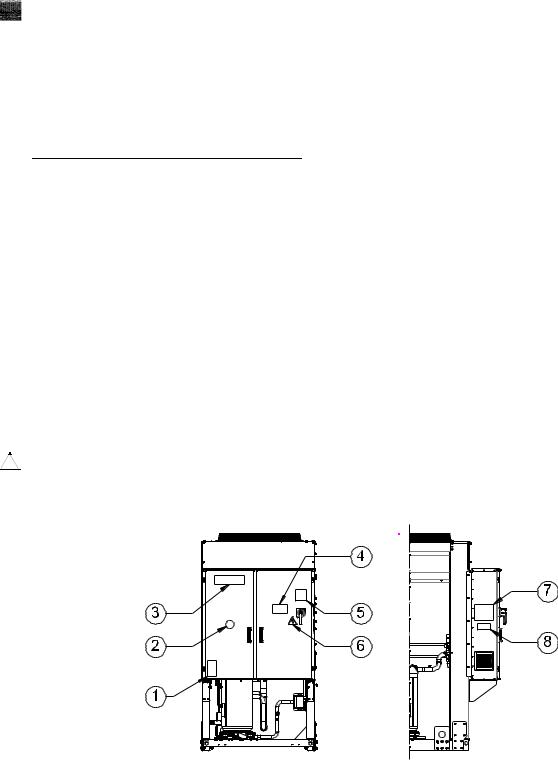
Figure 1 - Description of the labels applied to the electrical panel
Label Identification
1 |
– Non flammable gas symbol |
5 |
– Cable tightening warning |
2 |
– Gas type |
6 |
– Electrical hazard symbol |
3 |
– Manufacturer’s logo |
7 |
– Lifting instructions |
4 |
– Hazardous Voltage warning |
8 |
– Unit nameplate data |
D-EIMAC00804-14EU - 9/209
Label Identification
1 |
– Non flammable gas symbol |
5 |
– Cable tightening warning |
2 |
– Gas type |
6 |
– Hazardous Voltage warning |
3 |
– Unit nameplate data |
7 |
– Electrical hazard symbol |
4 |
– Manufacturer’s logo |
8 |
– Lifting instructions |
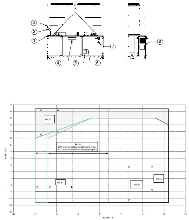
Figure 2 - Operating limits
Note
The above graphic represents a guidelines about the operating limits of the range. Please refer to Chiller Selection Software (CSS) for real operating limits working conditions for each size.
Legend
CIAT = Condenser Inlet Air Temperature (°C)
ELWT = Evaporator Leaving Water Temperature (°C)
A = Operation with Glycol (below 4°C Evap LWT)
B = Fan speed modulation or Speedtroll required (below 10°C Condens. Air Temp.)
C = Fan speed modulation or Speedtroll required (below 10°C and up to -10°C Condens. Air Temp.)* *Only referred to units with 4-5-6 fans
D = In this area units can work at partial load
E = In this area the unit minimum capacity might be higher than value shown in Technical Specification table F = Standard Efficiency (standard sound)
G = High Efficiency (standard sound)
D-EIMAC00804-14EU - 10/209
Safety
The unit must be firmly secured to the soil.
It is essential to observe the following instructions:
−The unit can only be lifted using the lifting points marked in yellow fixed to its base.
−It is forbidden to access the electrical components without having opened the unit main switch and switched off the power supply.
−It is forbidden to access the electrical components without using an insulating platform. Do not access the electrical components if water and/or moisture are present.
−Sharp edges and the surface of the condenser section could cause injury. Avoid direct contact and use adeguate protection device
−Switch off power supply, by opening the main switch, before servicing the cooling fans and/or compressors. Failure to observe this rule could result in serious personal injury.
−Do not introduce solid objects into the water pipes while the unit is connected to the system.
−A mechanical filter must be installed on the water pipe connected to the heat exchanger inlet.
−The unit is supplied with safety valves, that are installed both on the high-pressure and on the low-pressure sides
of the refrigerant circuit.
It is absolutely forbidden to remove all protections of moving parts.
In case of sudden stop of the unit, follow the instructions on the
Control Panel Operating Manual which is part of the onboard documentation delivered to the end user.
It is strongly recommended to perform installation and maintenance with other people. In case of accidental injury or unease, it is necessary to:
-keep calm
-press the alarm button if present in the installation site
-move the injured person in a warm place far from the unit and in rest position
-contact immediately emergency rescue personnel of the building or the Health Emergency Service
-wait without leaving the injured person alone until the rescue operators come
-give all necessary information to the the rescue operators
Avoid installing the chiller in areas that could be dangerous during maintenance operations, such as platforms without parapets or railings or areas not complying with the clearance requirements around the chiller.
Noise
The unit is a source of noise mainly due to rotation of compressors and fans.
The noise level for each model size is listed in sales documentation.
If the unit is correctly installed, operated and manteined the noise emission level do not require any special protection device to operate continuosly close to the unit without any risk. In case of installation with special noise requirements it could be necessary to install additional sound attenuation devices.
Moving and lifting
Avoid bumping and/or jolting during loading/unloading unit from the truck and moving it. Do not push or pull the unit from any part other than the base frame. Secure the unit inside the truck to prevent it from moving and causing damages. Do not allow any part of the unit to fall during transportation or loading/unloading.
All units are supplied with the lifting points marked in yellow. Only these points may be used for lifting the unit, as shown in the following Figure 3.
Both the lifting ropes and the spacing bars must be strong enough to support the unit safely. Please check the unit’s weight on the unit nameplate.
The unit must be lifted with the utmost attention and care following lifting label instructions; lift unit very slowly, keeping it perfectly level.
Positioning and assembly
All units are designed for installation outdoors, either on balconies or on the ground, provided that the installation area is free of obstacles that could reduce air flow to the condensers coil.
The unit must be installed on a robust and perfectly level foundation; should the unit be installed on balconies or roofs, it might be necessary to use weight distribution beams.
D-EIMAC00804-14EU - 11/209
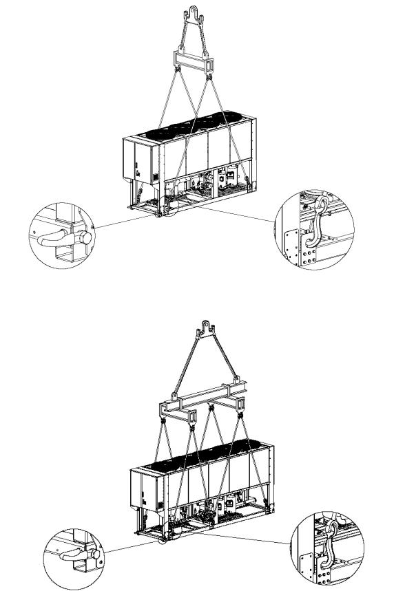
Figure 3 - Lifting the unit 4 fans version
5 fans version
D-EIMAC00804-14EU - 12/209

6 fans version
6 fans version
10-12 fans version
D-EIMAC00804-14EU - 13/209

(The drawing shows only the 8 fans version. For the 10-12 fans version the lifting mode is the same)
For installation on the ground, a strong concrete base, at least 250 mm thickness and wider than the unit must be provided. This base must be able to support the weight of the unit.
If the unit is installed in places that are easily accessible to people and animals, it is advisable to install protection grids for the condenser and compressor sections.
To ensure best performance on the installation site, the following precautions and instructions must be followed:
−Avoid air flow recirculation.
−Make sure that there are no obstacles to hamper air flow.
−Make sure to provide a strong and solid foundation to reduce noise and vibrations.
−Avoid installation in particularly dusty environments, in order to reduce soiling of condensers coils.
−The water in the system must be particularly clean and all traces of oil and rust must be removed. A mechanical water filter must be installed on the unit’s inlet piping.
Minimum space requirements
It is fundamental to respect minimum distances on all units in order to ensure optimum ventilation to the condenser coils. When deciding where to position the unit and to ensure a proper air flow, the following factors must be taken into consideration:
−avoid any warm air recirculation
−avoid insufficient air supply to the air-cooled condenser. Both these conditions can cause an increase of condensing pressure, which leads to a reduction in energy efficiency and refrigerating capacity.
Any side of the unit must be accessible for post-installation maintenance operations. Figure 4 shows the minimum space required.
Vertical air discharge must not be obstructed.
If the unit is surrounded by walls or obstacles of the same height as the unit, this must be installed at a distance no lower than (see Figure 4C or 4D). If these obstacles are higher, the unit must be installed at a distance no lower (see Figure 4E or 4F).
Should the unit be installed without observing the recommended minimum distances from walls and/or vertical obstacles, there could be a combination of warm air
recirculation and/or insufficient supply to the air-cooled condenser which could cause a reduction of capacity and efficiency.
In any case, the microprocessor will allow the unit to adapt itself to new operating conditions and deliver the maximum available capacity under any given circumstances, even if the lateral distance is lower than recommended, unless the operating conditions should affect personel safety or unit reliability.
When two or more units are positioned side by side, a distance of at least (see Figure 4G or 4H) between condenser banks is recommended.
For further solutions, please consult manufacturer representative.
Sound protection
When sound levels require special control, great care must be exercised to isolate the unit from its base by appropriately applying anti-vibration elements (supplied as an option). Flexible joints must be installed on the water connections, as well.
Water piping
Piping must be designed with the lowest number of elbows and the lowest number of vertical changes of direction. In this way, installation costs are reduced considerably and system performance is improved.
The water system must have:
1.Anti-vibration mountings in order to reduce transmission of vibrations to the structures.
2.Isolating valves to isolate the unit from the water system during service.
3.Manual or automatic air venting device at the system’s highest point.; drain device at the system’s lowest point.
4.Neither the evaporator nor the heat recovery device must be positioned at the system’s highest point.
5.A suitable device that can maintain the water system under pressure (expansion tank, etc.).
6.Water temperature and pressure indicators to assist the operator during service and maintenance.
Figure 4 - Minimum clearance requirements
D-EIMAC00804-14EU - 14/209
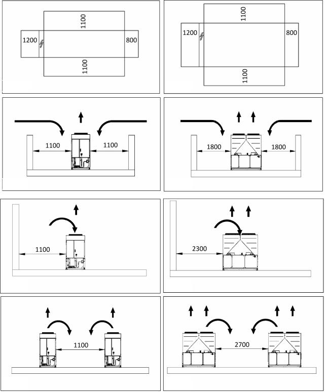
Fig. 4A
Fig. 4C
Fig. 4E
Fig. 4G
7.A filter or device that can remove particles from the fluid. The use of a filter extends the life of the evaporator and pump and helps to keep the water system in a better condition.
8.Evaporator has an electrical resistance with a thermostat that ensures protection against water freezing at ambient temperatures as low as –25°C. All the other water piping/devices outside the unit must therefore be protected against freezing.
9.The heat recovery device must be emptied of water during the winter season, unless an ethylene glycol mixture in appropriate percentage is added to the water circuit.
Fig. 4B
Fig. 4D
Fig. 4F
Fig. 4H
10.If case of unit substitution, the entire water system must be emptied and cleaned before the new unit is installed. Regular tests and proper chemical treatment of water are recommended before starting up the new unit.
11.In the event that glycol is added to the water system as anti-freeze protection, pay attention to the fact that suction pressure will be lower, the unit’s performance will be lower and water pressure drops will be greater. All unit-protection systems, such as anti-freeze, and low-pressure protection will need to be readjusted.
12.Before insulating water piping, check that there are no leaks.
D-EIMAC00804-14EU - 15/209

Figure 5 - Water piping connection for evaporator
1. |
Pressure Gauge |
5. |
Isolation Valve |
2. |
Flexible connector |
6. |
Pump |
3. |
Flow switch |
7. |
Filter |
4.Temperature probe
Figure 6 - Water piping connection for heat recovery exchangers
1.Pressure Gauge
2.Flexible connector
3.Temperature probe
Water treatment
Before putting the unit into operation, clean the water circuit. Dirt, scales, corrosion debrits and other material can accumulate inside the heat exchanger and reduce its heat exchanging capacity. Pressure drop can increase as well, thus reducing water flow. Proper water treatment therefore reduces
4.Isolation Valve
5.Pump
6.Filter
the risk of corrosion, erosion, scaling, etc. The most appropriate water treatment must be determined locally, according to the type of system and water characteristics. The manufacturer is not responsible for damage to or malfunctioning of equipment caused by failure to treat water or by improperly treated water.
Table 1 - Acceptable water quality limits
pH (25°C) |
6,8÷8,0 |
|
Total Hardness (mg CaCO3 / l) |
< 200 |
Electrical conductivity μS/cm (25°C) |
<800 |
|
Iron (mg Fe / l) |
< 1.0 |
Chloride ion (mg Cl - / l) |
<200 |
|
Sulphide ion (mg S2 - / l) |
None |
Sulphate ion (mg SO24 - / l) |
<200 |
|
Ammonium ion (mg NH4+ / l) |
< 1.0 |
Alkalinity (mg CaCO3 / l) |
<100 |
|
Silica (mg SiO2 / l) |
< 50 |
D-EIMAC00804-14EU - 16/209

Evaporator and recovery exchangers anti-freeze protection
All evaporators are supplied with a thermostatically controlled anti-freeze electrical resistance, which provides adequate antifreeze protection at temperatures as low as –25°C. However, unless the heat exchangers are completely empty and cleaned with anti-freeze solution, additional methods should also be used against freezing.
Two or more of below protection methods should be considered when designing the system as a whole:
−Continuous water flow circulation inside piping and exchangers
−Addition of an appropriate amount of glycol inside the water circuit
−Additional heat insulation and heating of exposed piping
−Emptying and cleaning of the heat exchanger during the winter season
It is the responsibility of the installer and/or of local maintenance personnel to ensure that described anti-freeze methods are used. Make sure that appropriate anti-freeze protection is maintained at all times. Failing to follow the instructions above could result in unit damage. Damage caused by freezing is not covered by the warranty.
Installing the flow switch
To ensure sufficient water flow through the evaporator, it is essential that a flow switch be installed on the water circuit. The flow switch can be installed either on the inlet or outlet water piping. The purpose of the flow switch is to stop the unit in the event of interrupted water flow, thus protecting the evaporator from freezing.
The manufacturer offers, as optional, a flow switch that has been selected for this purpose.
This paddle-type flow switch is suitable for heavy-duty outdoor applications (IP67) and pipe diameters in the range of 1” to 6”. The flow switch is provided with a clean contact which must be electrically connected to terminals shown in the wiring diagram.
Flow switch has to be tune to intervene when the evaporator water flow is lower than 50% of nominal flow rate.
Heat recovery
Units may be optionally equipped with heat recovery system. This system in made by a water cooled heat exchanger located on the compressors discharge pipe and a dedicated managment of condensing pressure.
To gurantee compressor operation within its envelope, units with heat recovery cannot operate with water temperature of the heat recovery water lower than 28°C.
It is a responsability of plant designer and chiller installer to gurantee the respect of this value (e.g. using recirculating bypass valve)
Electrical Installation
General specifications
All electrical connections to the unit must be carried out in compliance with laws and regulations in force.
All installation, management and maintenance activities must be carried out by qualified personnel.
Refer to the specific wiring diagram for the unit you have bougth. Should the wiring diagram not be on the unit or should it have been lost, please contact your manufacturer representative, who will send you a copy. In case of discrepance between wiring diagram and electrical panel/cables, please contact the manufacturer representative.
Only use copper conductors. Failure to use copper conductors could result in overheating or corrosion at connection points and could damage the unit.
To avoid interference, all control wires must be connected separately from the power cables. Use different electrical passage ducts for this purpose.
Before servicing the unit in any way, open the general disconnecting switch on the unit’s main power supply.
When the unit is off but the disconnecting switch is in the closed position, unused circuits are live, as well.
Never open the terminal board box of the compressors before having opened the unit’s general disconnecting switch.
Contemporaneity of single-phase and three-phase loads and unbalance between phases could cause leakages towards ground up to 150mA, during the normal operation of the units of the series.
If the unit includes devices that cause superior harmonics (like VFD and phase cut), the leakage towards ground could increases to very higher values (about 2 Ampere).
The protections for the power supply system have to be designed according to the above mentioned values.
Operation
Operator’s responsibilities
It is essential that the operator is appropriately trained and becomes familiar with the system before operating the unit. In addition to reading this manual, the operator must study the microprocessor operating manual and the wiring diagram in order to understand start-up sequence, operation, shutdown sequence and operation of all the safety devices.
During the unit’s initial start-up phase, a technician authorized by the manufacturer is available to answer any questions and to give instructions as to the correct operating procedures.
The operator must keep a record of operating data for every installed unit. Another record should also be kept of all the periodical maintenance and servicing activities.
If the operator notes abnormal or unusual operating conditions, he is advised to consult the technical service authorized by the manufacturer.
 If all power to the unit is turned off, the compressor heaters will become inoperable. Once power is resumed to the unit, the compressor and oil separator heaters must be energized a minimum of 12 hours before attempting to start the unit.
Failure to do so can damage the compressors due to excessive accumulation of liquid in the compressor.
Routine maintenance
Minimum maintenance activities are listed in Table 2
Service and limited warramty
All units are factory-tested and guaranteed for 12 months as of the first start-up or 18 months as of delivery.
These units have been developed and constructed according to high quality standards ensuring years of failure-free operation. It is important, however, to ensure proper and periodical maintenance in accordance with all the procedures listed in this manual and with good practice of machines maintenance.
We strongly advise stipulating a maintenance contract with a service authorized by the manufacturer in order to ensure efficient and problem-free service, thanks to the expertise and experience of our personnel.
It must also be taken into consideration that the unit requires maintenance also during the warranty period.
It must be borne in mind that operating the unit in an inappropriate manner, beyond its operating limits or not performing proper maintenance according to this manual can void the warranty.
Observe the following points in particular, in order to conform to warranty limits:
1.The unit cannot function beyond the specified limits
2.The electrical power supply must be within the voltage limits and without voltage harmonics or sudden changes.
3.The three-phase power supply must not have un unbalance between phases exceeding 3%. The unit must stay turned off until the electrical problem has been solved.
4.No safety device, either mechanical, electrical or electronic must be disabled or overridden.
5.The water used for filling the water circuit must be clean and suitably treated. A mechanical filter must be installed at the point closest to the evaporator inlet.
D-EIMAC00804-14EU - 17/209

6.Unless there is a specific agreement at the time of ordering, the evaporator water flow rate must never be above 120% and below 80% of the nominal flow rate.
Periodic obligatory checks and starting up of appliances under pressure
The units are included in category III of the classification established by the European Directive PED 97/23/EC.
For chillers belonging to this category, some local regulations require a periodic inspection by an authorized agency. Please check with your local requirements.
Table 2 - Routine maintenance programme
List of Activities |
Weekly |
Monthly |
Yearly/Seas |
|
|
(Note 1) |
onal |
|
|
|
(Note 2) |
General: |
|
|
|
Reading of operating data (Note 3) |
X |
|
|
Visual inspection of unit for any damage and/or loosening |
|
X |
|
Verification of thermal insulation integrity |
|
|
X |
Clean and paint where necessary |
|
|
X |
Analysis of water (5) |
|
|
X |
Check of flow switch operation |
|
X |
|
|
|
|
|
Electrical: |
|
|
|
Verification of control sequence |
|
|
X |
Verify contactor wear – Replace if necessary |
|
|
X |
Verify that all electrical terminals are tight – Tighten if necessary |
|
|
X |
Clean inside the electrical control board |
|
|
X |
Visual inspection of components for any signs of overheating |
|
X |
|
Verify operation of compressor and electrical resistance |
|
X |
|
Measure compressor motor insulation using the Megger |
|
|
X |
|
|
|
|
Refrigeration circuit: |
|
|
|
Check for any refrigerant leakage |
|
X |
|
Verify refrigerant flow using the liquid sight glass – Sight glass full |
X |
|
|
Verify filter dryer pressure drop |
|
X |
|
Analyse compressor vibrations |
|
|
X |
Analyse compressor oil acidity (Note 6) |
|
|
X |
|
|
|
|
Condenser section: |
|
|
|
Clean condenser banks (Note 4) |
|
|
X |
Verify that fans are well tightened |
|
|
X |
Verify condenser bank fins – Comb if necessary |
|
|
X |
Notes:
1.Monthly activities include all the weekly ones.
2.The annual (or early season) activities include all weekly and monthly activities.
3.Unit operating values should be read on a daily basis thus keeping high observation standards.
4.In environments with a high concentration of air-borne particles, it might be necessary to clean the condenser bank more often.
5.Check for any dissolved metals.
6.TAN (Total Acid Number) : ≤ 0,10 : No action
Between 0.10 and 0.19 : Replace anti-acid filters and re-check after 1000 running hours. Continue to replace filters until the TAN is lower than 0.10.
> 0,19 : Replace oil, oil filter and filter dryer. Verify at regular intervals.
Important information regarding the refrigerant used
This product contains fluorinated greenhouse gases covered by the Kyoto Protocol. Do not vent gases into the atmosphere.
Refrigerant type: |
R410A |
GWP(1) value: |
1975 |
(1)GWP = |
Global Warming Potential |
The refrigerant quantity necessary for standard operation is indicated on the unit name plate.
Real refrigerant quantity charged in the unit is listed on a silver sticker inside the electrical panel.
Periodical inspections for refrigerant leaks may be required depending on European or local legislation.
Please contact your local dealer for more information.
Disposal
The unit is made of metal, plastic and electronic parts. All these parts must be disposed of in accordance with the local regulations in terms of disposal.
Lead batteries must be collected and sent to specific refuse collection centres.
Oil must be collected and sent to specific refuse collection centres.
This manual is a technical aid and does not represent a binding offer. The content cannot be held as explicitly or implicitly guaranteed as complete, precise or reliable. All data and specifications contained herein may be modified without notice. The data communicated at the moment of the order shall hold firm. The manufacturer shall assume no liability whatsoever for any direct or indirect damage, in the widest sense of the term, ensuing from or connected with the use and/or interpretation of this manual.
We reserve the right to make changes in design and construction at any time without notice, thus the cover picture is not binding.
D-EIMAC00804-14EU - 18/209

1 |
ORIGINALANLEITUNG IN ENGLISCH |
2 |
Diese Anleitung ist ein wichtiges Dokument zur Unterstützung von Fachpersonal, es kann und soll dieses Personal jedoch nicht ersetzen. |
3 |
|
4 |
|
|
Danke für den Kauf dieses Kaltwassersatzes |
|
Ihnen gekauften Einheit und sie SIND ALS FESTER |
||||||
|
|
|
|
|
|
|
BESTANDTEIL DIESES HANDBUCHS ANZUSEHEN. |
||
|
LESEN SIE DIESE ANLEITUNG SORGFÄLTIG DURCH, |
Falls es Unstimmigkeiten zwischen diesem Handbuch und dem |
|||||||
|
BEVOR SIE DIE EINHEIT INSTALLIEREN. |
|
|
|
Gerätedokumenten gibt, ist in den Bord-Dokumenten achzusehen. Bei |
||||
|
NICHT FACHGERECHTES INSTALLIEREN KANN ZU |
Zweifeln ist sich an den Herstellervertreter zu wenden. |
|||||||
|
STROMSCHLAG, KURZSCHLUSS, LECKAGEN, BRÄNDEN |
Der Zweck dieses Handbuchs ist, es dem Installateur und dem |
|||||||
|
ODER BESCHÄDIGUNGEN DER GERÄTE ODER ZU |
ausgebildeten Bediener zu ermöglichen, eine einwand frei Installation, |
|||||||
|
VERLETZUNGEN VON PERSONEN FÜHREN . |
|
|
Inbetriebnahme und Wartung der Einheit ohne Risiko für Personen, |
|||||
|
DIE EINHEIT MUSS VON EINEM AUSGEBILDETEN |
Tiere oder Sachen sicherzustellen. |
|
|
|||||
|
BEDIENER/TECHNIKER INSTALLIERT WERDEN. |
|
Entgegennahme der Einheit |
|
|
||||
|
DIE INBETRIEBNAHME DER EINHEIT MUSS DURCH EINEN |
|
|
||||||
|
Die Einheit muss sofort auf eventuelle Schäden hinuntersucht werden, |
||||||||
|
AUTORISIERTEN UND AUSGEBILDETEN |
FACHMANN |
|||||||
|
DURCHGEFÜHRT WERDEN. |
|
|
|
|
bevor sie den Endaufstellort erreicht. Alle im Lieferschein aufgeführten |
|||
|
ALLE ARBEITEN MÜSSEN UNTER EINHALTUNG LOKALER |
Bauteile müssen untersucht und überprüft werden. |
|||||||
|
GESETZE UND VORSCHRIFTEN ERFOLGEN. |
|
|
Sollte die Einheit beschädigt sein, Sollte die Einheit beschädigt sein, nicht |
|||||
|
DIE INSTALLIERUNG UND INBETRIEBNAHME DER |
das beschädigte Material entfernen und sofort den Schaden dem |
|||||||
|
EINHEIT IST STRENGSTENS VERBOTEN, WENN DIE |
Frachtunternehmen melden, damit auch dieses den Schaden |
|||||||
|
ANLEITUNGEN DIESES HANDBUCHS NICHT KLAR SIND. |
untersucht. |
|
|
|||||
|
BEI ZWEIFELN SICH FÜR BERATUNG UND INFORMATION |
Den Schaden sofort dem Herstellervertreter melden, Fotos sind bei der |
|||||||
|
AN DEN VERTRETER DES HERSTELLERS WENDEN. |
Feststellung der Verantwortung hilfreich. |
|
||||||
Beschreibung |
|
|
|
|
|
Der Schaden darf nicht repariert |
werden, |
bevor der Vertreter des |
|
|
|
|
|
|
Transportunternehmens seine Untersuchung abgeschlossen hat. |
||||
|
|
|
|
|
|
|
|||
Bei der von Ihnen gekauften Einheit handelt es sich um eine "luftgekühlte |
Bevor die Einheit installiert wird, prüfen, dass da s Model und die |
||||||||
Kühlanlage", eine Maschine, die dazu dient, Wasser |
(oder Wasser- |
Spannungsversorgung auf dem Typenschild korrekt sind. Der Hersteller |
|||||||
Glykol-Mischung) innerhalb der im Folgenden beschriebenen Grenzen |
kann nicht für Schäden verantwortlich gemacht werden, die nach |
||||||||
zu kühlen. Die Betrieb der Einheit basiert auf eine r Dampfkompression, |
Annahme festgestellt werden. |
|
|
||||||
Kondensierung und Verdampfung |
nach dem |
Carnotkreislauf. Die |
Einsatzgrenzen |
|
|
||||
Hauptbestandteile sind: |
|
|
|
|
|
|
|
||
|
|
|
|
|
Lagerung |
|
|
||
- |
Scrollkompressor zur Erhöhung des Drucks des |
|
|
||||||
|
Kältemitteldampfes |
vom |
Verdampferdruck |
zum |
Umgebungsbedingungen müssen innerhalb der folgenden Grenzen |
||||
|
Kondensierungsdruck. |
|
|
|
|
|
liegen: |
|
|
- |
Verdampfer, in dem die unter schwachem Druck stehende |
Mindesttemperatur der Umgebung |
: |
-20°C |
|||||
|
Kältemittelflüssigkeit verdampft und somit das Wasser kühlt. |
|
Höchsttemperatur der Umgebung |
: |
+42 |
||||
- |
Verflüssiger, in dem |
unter |
Hochdruck |
stehender |
Da mpf |
Maximale Luftfeuchtigkeit |
: |
95% nicht kondensierend |
|
|
kondensiert und Wärme abgibt, die vom Kühlwasser über einen |
Eine Lager bein Temperaturen unter den Mindestemperaturen kann die |
|||||||
|
luftgekühlten Wärmetauscher in die Atmosphäre abgeitetl wird. |
Bauteile beschädigen. Lagerung über der Höchsttemperatur verursach |
|||||||
- |
Expansionsventil, das es ermöglicht, den Druck de r |
|
|
eine Öffnung der Sicherheitsventile. Lagerung in ko ndensierender |
|||||
|
Kondensflüssigkeit vom Kondensierungsdruck auf den |
|
Atmosphäre kann elektronische Bauteile beschädigen. |
||||||
|
Verdampferdruck zu senken. |
|
|
|
|
Betrieb |
|
|
|
|
|
|
|
|
|
|
|
|
|
Allgemeine Informationen
Alle Einheiten werden mit Maßzeichnungen , geprüften Zeichnungen, Typenschild; und Konformitätserklärung geliefert; diese Dokumente zeigen alle technischen Daten der von
betrieben werden.
Ein Betrieb außerhalb der angegebenen Grenzen kann die Einheit beschädigen.
Bei Zweifeln ist sich an den Herstellervertreter zu wenden.
Abbildung 1 - Aufkleber an der Schalttafel
Schilder-Anordnung
1 |
– Symbol für nicht entflammbare Gase |
5 |
– Warnhinweis zur Kabelbefestigung |
2 |
– Gasart |
6 |
– Warnzeichen vor elektrischen Gefahren |
3 |
– Herstellerlogo |
7 |
– Hebeanweisungen |
4 |
– Warnhinweis vor gefährlicher Spannung |
8 |
– Typenschild der Einheit |
D-EIMAC00804-14EU - 19/209

Schilder-Anordnung
1 |
– Symbol für nicht entflammbare Gase |
5 |
– Warnhinweis zur Kabelbefestigung |
2 |
– Gasart |
6 |
– Warnhinweis vor gefährlicher Spannung |
3 |
– Typenschild der Einheit |
7 |
– Warnzeichen vor elektrischen Gefahren |
4 |
– Herstellerlogo |
8 |
– Hebeanweisungen |
Ab bildung 2 - Einsatzgrenzen
Anmerkung
The obere Graphik zeigt die Grenzlinien des Einsatzbereichs. Bitte in der Kaltwassersatz Auswahlsoftware (CSS) für die reellen Betriebsgrenzen der Arbeitsbedingungen für jede Grö ße nach.
Zeichenerklärung
CIAT = Condenser Inlet Air Temperature (°C) (Verflüssig er Luftzuströmtemperatur (°C))
ELWT = Evaporator Leaving Water Temperature (°C) (Verdampfer-Auslass-Wassertemperatur (°C))
A = Betrieb mit Glykol (unter 4°C Verdampfer-AWT)
B = Einstellung der Gebläsegeschwindigkeit oder Geschwindigkeitskontrolle erforderlich (unter 10°C Kondens. Lufttemp.)
C= Einstellung der Gebläsegeschwindigkeit oder Geschwindigkeitskontrolle erforderlich (unter 10°C und bis tu -10 °C Kondens. Lufttemp.)* *Nur für Einheiten mit 4-5-6 Gebläsen
D= In diesem Bereich können Einheiten mit Teillast arbeiten
E= In diesem Bereich sollte die Mindestleistung der Einheit höher als der in der Tabelle mit den Techn ischen Spezifikationen
F= Standardeffizienz (Standardgeräusch)
G= Hocheffizienz (Standardgeräusch)
D-EIMAC00804-14EU – 20/209
Sicherheit
Die Einheit muss fest am Boden verankert sein.
Die folgenden Anweisungen müssen unbedingt beachtet werden:
−Die Einheit kann nur an den gelb markierten Hebepunkten angehoben werden, die fest mit der Grundplatte verbunden sind.
−Es ist verboten, auf die elektrischen Bauteile zuzugreifen, wenn nicht vorher der Haupttrennschalter der Einheit und die Stromversorgung ausgeschaltet wurden.
−Es ist verboten, auf die elektrischen Bauteile zuzugreifen, ohne eine isolierende Unterlage zu verwenden. Greifen Sie in Gegenwart von Wasser bzw. Feuchtigkeit nicht auf die elektrischen Bauteile zu.
−Scharfe Kanten und die Oberfläche des Verflüssigerabschnitts könnten Verletzungen verursachen. Direkten Kontakt vermeiden und geeignete Schutzvorrichtung benutzen.
−Stromversorgung ausgeschalten, indem der Hauptschalter geöffnet wird, bevor die Kühlgebläse und/oder Verdichter gewartet werden. Eine Nichtbeachtung dieser Vorschrift könnte zu schweren Verletzungen von Personen führen.
−Keine festen Gegenstände in die Wasserrohre einführen, wenn die Einheit an das System angeschlossen ist.
−Am Wasserrohr, das an den Wärmetauschereingang angeschlossen ist, muss ein mechanischer Filter installiert werden.
−Die Einheit wird mit Sicherheitsventilen ausgeliefert. Diese sind sowohl an der Hochals auch an der
Niederdruckseite des Kältemittelkreislaufs installiert.
Es ist strengstens verboten, irgendeine der Schutzvorrichtungen der bewegten Teile zu entfernen.
Bei einem plötzlichen Stopp der Einheit sind die An weisungen in der Betriebsund Bedienungsanleitung zu beachten, die Teil der mit dieser Anleitung dem Endnutzer gelieferten BordDokumentation ist.
Installation und Wartung sollten unbedingt zusammen mit anderen Personen ausgeführt werden. Bei Unfällen oder Unwohlsein sind folgende Regeln zu beachten:
-Ruhe bewahren
-Notruftaste drücken, wenn am Installationsort vorh anden
-Verletzte Person an einen warmen Ort fern von der Einheit in Ruheposition bringen
-Unverzüglich das Rettungspersonal des Gebäudes oder den Rettungsdienst rufen
-Bis zum Eintreffen des Rettungspersonals bei der verletzten Person bleiben
-Dem Rettungspersonal alle erforderlichen Informationen geben.
Die Kühlanlage nicht an Orten installieren, die während den Wartungsarbeiten gefährlich sein könnten, wie Arbeitsbühnen ohne Geländer oder Gitter oder Bereiche, die nicht den Sauberkeitsanforderungen um den Kühlanlage erfüllen.
Lärm
Die Einheit ist Quelle von Geräuschen, die hauptsächlich durch die Drehbewegungen des Verdichters und der Gebläse hervorgerufen werden.
Der Geräuschpegel für jede Modelgröße ist in den Verkaufsdokumenten aufgelistet.
Wenn die Einheit korrekt installiert ist, und korrekt betrieben und gewartet wird, erfordert die Geräuschentwicklung keine spezielle Schutzvorrichtung, um durchgängig ohne Risiko in der Nähe der Einheit arbeiten zu können.
Bei einer Installation mit speziellen Geräuschanforderungen könnte es notwendig werden, zusätzliche Schalldämmvorrichtungen zu installieren.
Bewegung und Anheben
Anstoßen und/oder schütteln sind während des Ladens/Abladens der Einheit vom Lastwagen und bei ihrer Bewegung zu vermeiden. Die Einheit nicht an einem anderen Teil als dem Grundgestell ziehen oder schieben. Die Einheit im Lastwagen sichern, damit sie sich nicht bewegt und Schäden verursachen kann. Keines der Teile der Einheit darf während des Transportes oder beim Laden/Abladen herabfallen.
Alle Einheiten besitzen gelb markierte Hebestellen. Die Einheit darf nur über diese Stellen angehoben werden, wie i m Folgenden gezeigt Abbildung .
Sowohl die Trageseile als auch die Querträger müssen die Einheit sicher tragen können. Das Gewicht der Einheit auf dem Typenschild überprüfen.
Die Einheit unter größter Vorsicht und Aufmerksamke it nach folgenden Hebeanweisungen gehoben werden; die Einheit sehr langsam anheben und sie in perfektem Gleichgewicht halten.
Aufstellung und Zusammenbau
Alle Einheiten werden für eine Aufstellung in Außen bereichen entwickelt, entweder Balkons oder auf dem Boden, wobei der Installationsbereich frei von Hindernissen sein muss, die den Luftstrom zu den Verflüssigerregister behindern kön nten.
Die Einheiten müssen auf einem festen und perfekt e benen Untergrund installiert werden; soll die Einheit auf Balkonen oder Dächern installierte werden, müssen unter Umständen Lastverteilungsstangen benutzt werden.
D-EIMAC00804-14EU – 21/209

Abbildung 3 - Heben der Einheit
Version mit 4 Gebläsen
Version mit 5 Gebläsen
D-EIMAC00804-14EU – 22/209
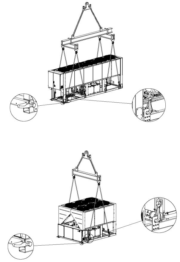
Version mit 6 Gebläsen
Version mit 6 Gebläsen
D-EIMAC00804-14EU – 23/209

Version mit 10-12 Gebläsen
(Die Zeichnung zeigt nur die Version mit 8 Gebläsen . Für die Version mit 10-12 Gebläsen ist die Hebewe ise die gleiche)
Die die Installation auf dem Boden ist eine mindestens 250 mm starke Betongrundplatte anzubringen, die über die Einheit hinausragt. Die Grundplatte muss in der Lage sein, das Gewicht Einheit zu tragen.
Wenn die Einheit in einem Bereich installiert wird, der einfach für Menschen und Tiere zugänglich ist, ist es ratsam Schutzgitter für die Verflüssigerund Verdichterabschnitte anzubringen.
Um eine optimale Leistungserbringung bei der Installation sicherzustellen, sind folgende Vorsichtsmaßnahmen und Anleitungen zu beachten:
−Luftstromrückführung vermeiden.
−Sicherstellen, dass keine Hindernisse den Luftstrom behindern.
−Eine starken und festen Untergrund erstellen, um Geräuschund Vibrationsentwicklungen zu vermeiden.
−Eine Installation in besonders staubiger Umgebung vermeiden, um eine Verschmutzung des Verflüssigerregisters zu vermeiden.
−Das Wasser im System muss besonders sauber sein und alle Ölreste und Roststellen müssen entfernt werden. Ein mechanischer Wasserfilter muss auf der Zulaufleitung der Einheit installiert werden.
Minimaler Raumbedarf
Es ist außerordentlich wichtig, dass die Mindestabstände aller Einheiten eingehalten werden, um eine optimale Ventilation der Verflüssigerregister sicherzustellen.
Bei der Entscheidung, wo die Einheit auszustellen und ein ausreichender Luftstrom zu sichern ist, müssen folg ende Faktoren berücksichtigt werden:
−jede Warmluftzirkulation vermeiden
−unzureichende Luftversorgung zu den luftgekühlten Verflüssigern vermeiden.
Beide Bedingungen können eine Erhöhung des Kondensd rucks verursachen, was zu einer Reduzierung des Energienutzungsgrates und der Kühlleistung führt.
Jede Seite der Einheit muss für Wartungsarbeiten na ch der Installation zugänglich sein. Abbildung 4 zeigt den Mindestplatzbedarf.
Vertikaler Luftauslass darf nicht verstopft werden.
Wenn die Einheit von Mauern oder Hindernissen umgeben ist, die die gleiche Höhe wie die Einheit besitzen, muss sie in einem Abstand nicht unter (siehe Abbildung 4C oder 4D) installiert werden. Wenn diese Hindernisse höher sind, muss die Einheit in e inem Abstand nicht unter (siehe Abbildung 4E oder 4F) installiert werden.
Sollte die Einheit installiert werden, ohne dass die empfohlenen Mindestabstände zu den Mauern und/oder vertikalen Hindernissen
eingehalten werden, könnte es zu einer Verbindung d er rückströmenden Warmluft uns/oder unzureichender Ver sorgung zu den luftgekühlten Hindernissen kommen, was eine Red uzierung der Leistung wie des Wirkungsgrates verursacht.
Auf alle Fälle erlaubt der Mikroprozessor der Einheit, sich an neue Arbeitsbedingungen anzupassen und die maximal verfü gbare Leistung unter den gegebenen Umständen zu liefern,selbst wenn der Seitenabstand niedriger als der erlaubte ist, außer wenn die Arbeitsbedingungen die persönliche Sicherheit oder der der Sicherheit der Einheit beeinträchtigen.
Wenn zwei oder mehr Einheiten nebeneinander aufgestellt sind, wird ein Abstand von mindestens (siehe Abbildung 4G oder 4H) zwischen den Verflüsserbanken empfohlen.
Für weitere Lösungen einer Herstellervertreter zu R ate ziehen.
Geräuschschutz
Wenn die Geräuschpegel besonderer Überprüfungen bedarf, muss besondere Sorgfalt bei der Isolierung der Einheit von ihrer Grundplatte gelegt werden, indem Vibrationsdämpfer (als Option mitgeliefert) angebracht werden. Zudem müssen flexible Anschlusst eile an den Wasseranschlüssen installiert werden.
Wasserleitungen
Die Rohre müssen mit der geringsten anzahl an Rohrk nien und der geringsten anzahl an vertikalen Richtungswechseln ausgelegt sein. Auf diese Weise werden die Installationskosten deutlich gesenkt und die Systemleistung gestärkt.
Das Wassersystem muss haben:
1.Vibrationsdämpfervorrichtungen zur Verringerung der Übertragung von Vibrationen auf die Struktur.
2.Selbstschlussventile zur Isolierung der Einheit während des Betriebs vom Wassersystem.
3.Manuelle oder automatische Entlüftungsvorrichtun gen an der höchsten Stelle des Systems; Entwässerungsvorrichtung an der tiefsten Stelle des Systems.
4.Weder der Verdampfer noch die Wärmerückgewinnungsvorrichtung dürfen sich am höchs ten Punkt des Systems befinden.
5.Eine passende Vorrichtung, das das Wassersystem unter Druck halten kann (Ausdehnungstank usw.).
6.Anzeiger für Wassertemperatur und Druck zur Unte rstützung des Bedieners während des Betriebs und Wartung.
D-EIMAC00804-14EU – 24/209
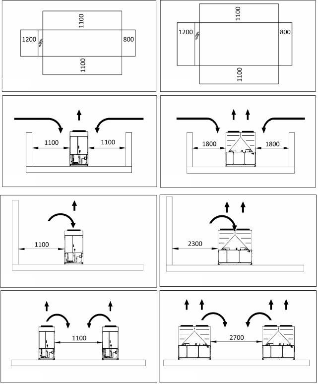
Abbildung 4 - Minimale Freiraumanforderungen
Abb. 4A
Abb. 4C
Abb. 4E
Abb. 4G
7.Ein Filter, der Festpartikel aus dem Fluid entfernen kann. Der Gebrauch eines Filters verlängert das Leben des Verdampfers und der Pumpe und hilft, das Wassersystem in einem guten Betriebszustand zu halten.
8.Der Verdampfer besitzt eine elektrischen Widerstand mit einem Thermostat, das einen Gefrierschutz bei Umgebungstemperaturen bis zu -25 °C bildet. Alle anderen Wasserrohre/Wasservorrichtung außerhalb der Einheit müssen daher gegen Gefrieren geschützt werden.
9.Die Wärmerückgewinnungsvorrichtung muss währenddes Winters frei von Wasser sein, es sei denn, es wird kein Ethylen-
Abb. 4B
Abb. 4D
Abb. 4F
Abb. 4H
Glykol-Gemisch in angemessenen Anteilen wird dem Kreislaufwasser beigemengt.
10.Bei einem Austausch der Einheit, muss das gesamte Wassersystem wasserleer und gereinigt sein, bevor die neue Einheit installiert wird. Es werden regelmäßige Tests und eine einwandfreie Wasseraufbereitung empfohlen, bevor die neue Einheit in Betrieb genommen wird.
11.Bei der Zugabe von Glykol als Gefrierschutzmittel in das Wassersystem ist darauf zu achten, dass der Ansaugdruck absinkt, die Leistung der Einheit wird geringer und das Absinken des Wasserdrucks wird größer. Alle Schutzsysteme de r Einheit,
D-EIMAC00804-14EU – 25/209

wie Gefrierschutz und Niederdruckschutz müssen neu eingestellt werden.
12.Bevor die Wasserrohre isoliert werden, überprüf en, dass keine Lecks vorhanden sind.
Abbildung 5 - Wasserrohranschluss für den Verdampfe r
1. |
Druckmesser |
5. |
Isolierventil |
2. |
Flexibler Anschluss |
6. |
Pumpe |
3. |
Durchflussregler |
7. |
Filter |
4.Temperaturfühler
Abbildung 6 - Wasserrohranschluss für Wärmerückgewi nnungstauscher
1.Druckmesser
2.Flexibler Anschluss
3.Temperaturfühler
Wasseraufbereitung
Bevor die Einheit in Betrieb genommen wird, den Wasserkreislauf reinigen. Schmutz, Kesselstein, Korrosionsablagerungen und andere Materialien könne n sich in dem Wärmerückgewinnungstauscher ansammeln und seine Wärmetauschleistung verringern. Druckabfall kann ebenso zunehmen und somit den Wasserdurchfluss verringern. Eine angemessene Wasseraufbereitung reduziert daher das Risiko
4.Isolierventil
5.Pumpe
6.Filter
von Korrosion, Kesselsteinbildung usw. Die geeignetste Wasseraufbereitung muss vor Ort entschieden werden, je nach Systemart und Wassereigenschaften.
Der Hersteller ist nicht verantwortlich für Schädenan dem Gerät, wenn keine oder eine unzureichende Wasseraufbereitung vorgenommen wird.
Tabelle 1 - Annehmbare Grenzen Wasserqualität
pH (25°C) |
÷ |
8,0 |
|
Gesamthärte (mg CaCO3 / l) |
< |
200 |
|
|
6,8 |
|
|
|
|
||
μ |
< |
|
|
Eisen (mg Fe / l) |
|
< |
1.0 |
Elektrische Leitfähigkeit S/cm (25°C) |
800 |
|
|
|
|
||
Chloridion (mg Cl - / l) |
< |
|
|
Sulfidion (mg S2 - / l) |
|
Nichts |
|
|
200 |
|
|
|
|
|
|
Sulfation-Ion (mg SO24 - / l) |
< |
|
|
Ammonium-Ion (mg NH4+ |
/ l) |
< |
1.0 |
|
200 |
|
|
|
|
||
Alkalinität (mg CaCO3 / l) |
< |
|
|
Siliciumdioxid (mg SiO2 / l) |
< |
50 |
|
|
100 |
|
|
|
|
||
D-EIMAC00804-14EU – 26/209

Verdampfer und Rückgewinnungstauscher Gefrierschutz
Alle Verdampfer werden mit einem thermostatisch gesteuerten, elektrischen Gefrierschutzwiderstand geliefert, der für einen an gemessenen Gefrierschutz bei Temperaturen bis -25 °C sorgt. Solange die Wärmetauscher nicht vollständig leer und mit Gefrierschutzmittel gesäubert sind, sollten dennoch zusätzlicheMittelfürdenGefrierschutzeingesetztwerden.
Zwei oder mehr der unteren Schutzarten sollten in Betracht gezogen werden, wenndas Systemals Ganzes ausgelegt ist:
−KontinuierlicherWasserkreislauf indenRohrenundindenTauschern
−ZugabeeineangemessenenMengeanGlykolindenWasserkreislauf
−ZusätzlicheHitzeisolierungundheißenausgesetzterRohre
−LeerenundReinigendes Hitzeaustauschers währendderWinterzeit Es liegt in der Verantwortung des Installateurs und/oder des Wartungspersonals vor Ort, sicherzustellen, dass die beschriebenen Gefrierschutzarten benutzt werden. Sicherstellen, dass angemessener Gefrierschutzdauerhaft aufrechterhalten wird. EineNichtbefolgung der obigen Anleitungen kann zu einem Schaden an der Einheit fü hren. Schaden durch Gefrierenist nicht vonderGarantieabgedeckt.
Installierung des Durchflussreglers
Um ausreichendenWasserdurchfluss durch den Verdampfer sicherzustellen, ist die Installierung eines Durchflussreglers von grundlegender Bedeutung. Der Durchflussregler kann entweder auf demWasserzuoder-ablauf installiert werden. Die Aufgabe des Durchflussreglers ist es, die Einheit bei einer Unterbrechung des Durchflusses anzuhalten, wodurch der Verdampfer vor Gefrierengeschützt wird.
Der Hersteller bietet als Optional einen Durchflussregler an, der zu diesem Zweck ausgewählt wurde.
Dieser Schaufel-Durchflussregler ist für Hochleistu ngsanwendungen im Außenbereich(IP67)undRohrdurchmesservon1”bis 6”ausgelegt.
Der Durchflussregler ist mit einem spannungsfreien Kontakt versehen, der elektrischmit denKlemmenimelektrischenSchaltplanverbundenseinmuss. Der Durchflussregler muss so eingestellt sein, das er eingreift, wenn der Verdampfer-Wasserdurchfluss niedriger als 50% des Nenndurchflusses beträgt.
Wärmerückgewinnung
Einheiten können optional mit einem Wärmerückgewinnungssystem ausgestattetsein.
Dieses System besteht aus einem wassergekühlten Wärmetauscher an der AbflussleitungdesVerdichters undeinerSteuerungdes Kondensdruckes. Zu Garantierung des Verdichterbetriebs in seinem Rahmen, können Einheiten mit Wärmerückgewinnung nicht mit Wassertemperaturen des Wärmerückgewinnungswassers vonunter28°Carbeiten.
Es liegt in der Verantwortung des Projektplaners und
Kühlanlageninstallateurs, die Einhaltung dieses |
Wer ts (z.B. durch |
Anwendungeines Überbrückungsventils)zugarantiere |
n. |
Elektroinstallation
Allgemeine Spezifikationen
AlleelektrischenAnschlüssezurEinheit müssenin Übereinstimmung mit dengeltendenGesetzenundVorschriftendurchgeführt werden.
AlleInstallations-,Steuerungs-undWartungsarbeitenmüssendurch ausgebildetes Personaldurchgeführt werden.
Im spezifischenSchaltplandervonIhnen gekauftenEinheit nachsehen. SolltederSchaltplannicht beiderEinheit sein, odersollte erverlorengegangensein, sowendenSie sichbitteandennächsten Herstellervertreter, derIhneneineKopiezusenden wird.
BeieinerAbweichungdes Schaltplans undelektrischen Schalttafel/Kabel, wendenSiesichbitteandenHerstellervertreter.
Nur Kupferleiter benutzen. Wenn keine Kupferleiter verwendet wurden kann dies zu einer Überhitzung oder zu Korrosion an den Kontaktpunkten führen, was dieEinheit beschädigenkönnte.
Im Interferenzen zu vermeiden, müssen alle Steuerle itungen von den Stromkabeln getrennt angeschlossen werden. Für dies en Zwecke unterschiedlicheLeitungsführungenbenutzen.
Bevor die Einheit in Betrieb genommen wird, den Haupttrennschalter auf der Haupt-StromversorgungderEinheit öffnen.
Wenn die Einheit ausgeschaltet ist, der Hauptschalter sich aber in geschlossener Stellung befindet, stehen auch ungenutzte Kreisläufe unter Spannung.
Niemals den Anschlusskasten der Schalttafel des Verdichters öffnen, wenn vorhernicht derHaupttrennschalterderEinheit geö ffnet wurde.
Gleichzeitigkeit von Einzelphasenund Dreiphasenladungen und einem Ungleichgewicht zwischen den Phasen könnte während des normalen
Betriebs der Einheiten der Reihe zu einem Erdableitungsstrom bis zu 150mA führen.
Wenn die Einheit Vorrichtungen beinhaltet, die Oberschwingungen verursachen (wie Frequenzumrichter und Phasenanschnittsteuerung), könnte der Erdableitungsstrom bis zu sehr großen We rten ansteigen (etwa 2 Ampere).
Die Schutzvorrichtungen für das Stromversorgungssys tem muss auf die obenerwähntenWerteausgelegtsein.
Betrieb
Verantwortung des Bedieners
Es ist vonWichtigkeit, dass der Bediener angemessen ausgebildet ist undmit dem System vertraut ist, bevor er die Einheit bedient. Zusätzlich zum Lesen dieses Handbuchs muss der Bediener das Bedienungshandbuch des Mikroprozessors und den Schaltplan lesen, um der Ablauf der Inbetriebnahme, den Betrieb und die Anhalteablauf, sowie die Sicherheitsvorrichtungenzuverstehen.
Während der anfänglichen Startphase ist ein vom Hersteller autorisierter Techniker zugegen, um auf alle Fragen Antworten zu geben und AnweisungenzudenkorrektenBetriebshandhabungenzugeben.
Der Bediener muss eine Übersicht über alle Betriebs daten für jede installierte Einheit aufbewahren. Ebenso sollte eine weitere Übe rsicht über alle regelmäßigenWartungsarbeitenundBetriebstätigenufbewahrt werden.
Wenn der Bediener ungewöhnliche oder unübliche Betr iebszustände bemerkt, muss er sich an den vom Hersteller autorisierten technischen Kundendienst wenden.
 WennalleStromversorgungmitdenEinheitenunterbrochen werden, sinddieHeizverdichternicht mehrbetriebsbereit.WenndieStromversorgung zurEinheit wiederaufgenommenwird, müssenderVer dichterunddie Ölabscheiderheizerfürmindestens 12StundenmitSt rom versorgt werden, bevorderStart derEinheit versucht werdenkann.
Wenndies unterlassenwird, kannderVerdichterwegenderübermäßigen AnsammlungvonFlüssigkeit imVerdichterbeschädigtwerden.
OrdentlicheWartung
DieminimalenWartungsarbeitensindaufgelistet inTabelle.
Kundendienst und beschränkte Garantie
Alle Einheiten wurden werkseitig getestet und besitzen eine Garantier von 12 MonatenabdererstenInbetriebnahmeodervon18 MonatenabLieferung. Diese Einheiten wurden nach höchsten Qualitätsstandards geplant und gefertigt, die einen jahrelangen, störungsfreien Be trieb sichern. Es ist dennoch wichtig, dass eine angemessene und regelmäßige Wartung in Übereinstimmung mit allen in diesem Handbuch aufgef ührten Vorgehen und mit fachgerechter Durchführung von Maschinenwartung en eingehalten werden.
Wir raten dringend einen Wartungsvertrag mit einem vom Hersteller autorisierten Kundendienstzentrum abzuschließen, um einen wirksamen und problemlosen Betrieb durch die Fachkenntnis und Erfahrung unseres Personals sicherzustellen.
Es muss ferner in Betracht gezogen werden, dass die Einheit auch während derGarantiezeit eineWartungbenötigt.
Esmussberücksichtigt werden, dass derBetriebder Einheit auf unsachgemäßeWeise, überihreLeistungsgrenzenhinaus oderdurch UnterlassungeinerangemessenenWartungnachdiesem Handbuchdazu führenkannkann, dass dieGarantieverfällt.
Die folgenden Punkte sind besonders zu beachten, um die Garantiegrenzen einzuhalten:
1.Die Einheit darf nicht über die spezifischen Gre nzen hinaus betrieben werden
2.Die elektrische Stromversorgung muss mit den Spannungsgrenzen und ohne Spannungsoberschwingungen oder plötzlichen Schwankungensein.
3.Die Drei-Phasen-Stromversorgung darf keine Spannungsunsymmetrie zwischen den Phasen aufweisen, die über 3% liegt. D ie Einheit muss ausgeschaltet sein, bis das elektrischeProblem gelöstist.
4.KeineSicherheitsvorrichtung, wedermechanischnochelektrischoder elektronischdarf deaktiviert oderüberbrückt werde n.
5.Das Wasser zum Füllen des Wasserkreislaufs muss sauber und angemessenaufbereitet sein. EinmechanischerFiltermusssonahwie möglichamVerdampfer-Einlassinstalliertwerden.
6.AbgesehenvoneinerspezifischenÜbereinkunft be iderBestellungdarf derVerdampfer-Wasserdurchfluss niemals über120% u ndunter80% des Nenndurchflusses liegen.
D-EIMAC00804-14EU – 27/209

Vorgeschriebene regelmäßige Kontrollen und
Inbetriebnahme von Druckgeräten
Die Einheiten gehören zu Kategorie III der Klassifi zierung gemäß EGDruckgeräterichtliniePED97/23/EG.
Für zu dieser Kategorie gehörende Kaltwassersätze schreiben einige örtliche Bestimmungen eine regelmäßige Inspektion durch eineautorisierte Stelle vor. BitteinformierenSiesichüberdieörtlichen Vorsc hriften.
Tabelle 2 - Das ordentliche Wartungsprogramm
Lister der Maßnahmen |
|
Wöchentli |
Monatlich |
Jährlich/Jahr |
|
|
ch |
(Anmerkung 1) |
eszeitlich |
|
|
|
|
(Anmerkung 2) |
Allgemein: |
|
|
|
|
Lesen der Betriebsdaten (Anmerkung 3) |
|
X |
|
|
Sichtkontrolle der Einheit auf irgendwelche Schädenund/oder Lockerungen |
|
X |
|
|
Überprüfung der Unversehrtheit der Wärmeisolierung |
|
|
|
X |
Sauber und lackiert, wo benötigt |
|
|
|
X |
Wasseranalyse (5) |
|
|
|
X |
Überprüfung der Arbeit des Durchflussreglers |
|
|
X |
|
|
|
|
|
|
Elektroinstallation: |
|
|
|
|
Überprüfung der Kontrollsequenz |
|
|
|
X |
Überprüfen der Verschleißes des Schaltschützes - Au swechseln, wenn nötig |
|
|
X |
|
Überprüfen, dass alle elektrischen Klemmen angezeig |
t sind - Anziehen, falls |
|
|
X |
nötig |
|
|
|
|
Das Innere des elektrischen Schaltschranks reinigen |
|
|
|
X |
Sichtkontrolle der Bauteile nach irgendwelchen Anzeichen einer Überhitzung |
|
X |
|
|
Kontrolle des Verdichters und des elektrischen Widerstands |
|
X |
|
|
Messen der Isolierung des Verdichtermotors mit dem Megger |
|
|
X |
|
|
|
|
|
|
Kühlkreislauf: |
|
|
|
|
Kontrolle nach Kältemittellecks |
|
|
X |
|
Kontrolle des Kältemittelflusses über das Sichtfenster - Sichtfenster voll |
X |
|
|
|
Überprüfung des Filtertrockners Druckabfall |
|
|
X |
|
Analyse der Verdichtervibrationen |
|
|
|
X |
Analyse Verdichter Säuregehalt Öl (Anmerkung 6) |
|
|
|
X |
|
|
|
|
|
Verflüssigerabschnitt: |
|
|
|
|
Reinigen der Verflüsserbanken (Anmerkung 4) |
|
|
|
X |
Überprüfen, dass die Gebläse gut angezogen sind |
|
|
|
X |
Überprüfen der Kühlrippen der Verflüsserbank - Kämm |
en, falls nötig |
|
|
X |
Anmerkungen:
1.Monatliche Tätigkeiten umfassen alle wöchentlichen.
2.Die jährlichen (oder jahreszeitlichen) Tätigkenit umfassen alle wöchentlichen und monatlichen.
3.Die Betriebswerte der Einheiten sollten täglichabgelesen werden, um höhen Inspektionsstandard zu h alten.
4.In Umgebungen mit einer hohen Konzentration von luftgetragener Partikel kann es sein, dass die Verflüssigerbank öfters gereinigt werden muss.
5.Kontrolle nach aufgelösten Metallen.
6.TAN (Total Acid Number) : ≤ 0,10 : Kein Maßnahme
Zwischen 0,10 und 0,19 : Den Säureschutzfilter ersetzen und Nachprüfung nach 1000 Betriebsstunden. Den Filter solange ersetzen, bis TAN unter 0,10 liegt.
> 0,19 : Öl, Ölfilter und Filtertrockner ersetzen. I nnerhalb regulärer Zeitabständen überprüfen.
Wichtige Hinweise zum verwendeten Kältemittel
Dieses Produkt enthält fluorierte Treibhausgase, die unter das KyotoProtokoll fallen. Diese Gase dürfen nicht in die Um welt freigesetzt werden.
Kältemitteltyp:
GWP-Wert (1): (1)GWP =
Die Kältemittelmenge für Standardbetrieb ist auf dem Typenschild der Einheit angegeben.
Die reelle in der Einheit eingefüllte Kältemittelmenge ist auf einem Silberaufkleber im Innern des elektrischen Schaltschranks angegeben. Europäische oder örtliche Bestimmungen können regelmäßige Kontrollen auf Kältemittel-Leckagen vorschreiben.
Weitere Informationen hierzu erteilt der örtliche F achhändler.
Entsorgung
Die Einheit enthält Bauteile aus Metall und Kunststoff sowie elektronische Teile. Alle diese Teile müssen entspr echend den örtlich geltenden Entsorgungsvorschriften entsorgt werden.
Bleibatterien müssen den zuständigen Schadstoff-Sammelstellen zugeführt werden.
Altöl muss den zuständigen Schadstoff-Sammelstellen zugeführt werden.
Diese Handbuch ist eine technische Hilfe und stellt keine bindendes Angebot dar. Der Inhalt kann nicht als explizit oder implizit garantiert angesehen werden, was Vollständigkeit, Genauigkeit oder Verlässlichkeit betrifft. Alle hier enthaltenen Daten und Spezifikationen dürfen ohne vorherige Ankündigung geändert werden. Das zum Zeitpunkt der Bestellung angegeben Datum ist verbindlich.
Der Hersteller übernimmt keine Haftung für jeden di rekten oder indirekten Schaden im weitesten Sinn des Wortes, der aus dem Gebrauch und/oder Deutung dieses Handbuchs hervorgeht oder mit ihm in Verbindung steht.
Wir behalten uns vor, jederzeit unangekündigt gesta lterische und konstruktive Änderungen vorzunehmen, daher ist das Titelbild nicht verbindlich.
D-EIMAC00804-14EU – 28/209
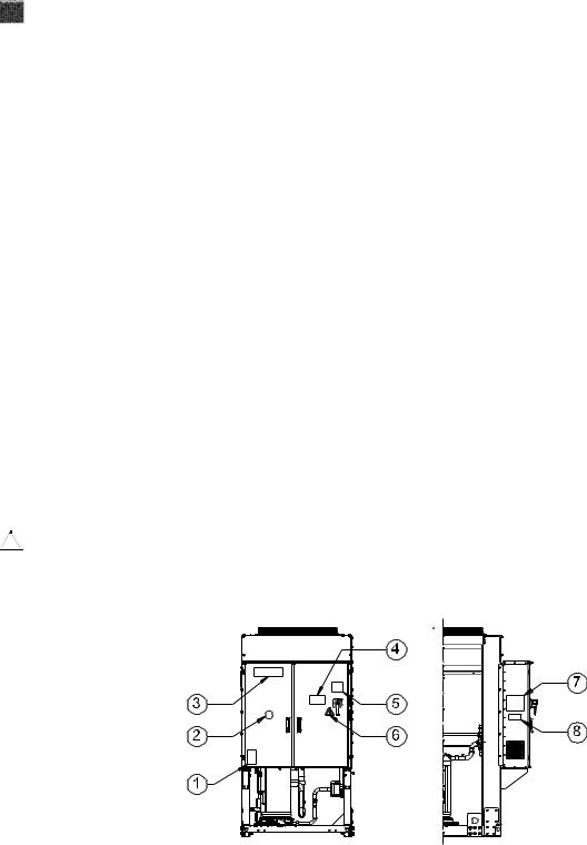
INSTRUCTIONS ORIGINALES EN ANGLAIS
Ce manuel constitue un document de support important pour le personnel qualifié, mais ne peut toutefois pas remplacer le personnel lui-même.
Merci d'avoir choisi ce chiller
LIRE ATTENTIVEMENT LE PRESENT MANUEL AVANT DE PROCEDER A L'INSTALLATION ET A LA MISE EN MARCHE DE L'UNITE.
UNE INSTALLATION IMPROPRE PEUT CAUSER DES DECHARGES ELECTRIQUES, DES COURTS-CIRCUITS, DES FUITES, DES INCENDIES ET D'AUTRES DOMMAGES A L'APPAREIL OU LESIONS AUX PERSONNES.
L'UNITE DOIT ETRE INSTALLEE PAR UN OPERATEUR/TECHNICIEN PROFESSIONNEL.
LA MISE EN MARCHE DE L'UNITE DOIT ETRE EFFECTUEE PAR DES PROFESSIONNELS AUTORISES ET PREPARES. TOUTES LES ACTIVITES DOIVENT ETRE EFFECTUEES CONFORMEMENT AUX LEGISLATIONS ET AUX NORMES LOCALES EN VIGUEUR.
L'INSTALLATION ET LA MISE EN MARCHE DE L'UNITE SONT ABSOLUMENT INTERDITES SI TOUTES LES INSTRUCTIONS CONTENUES DANS LE PRESENT MANUEL NE SONT PAS CLAIRES.
EN CAS DE DOUTES, POUR TOUTE INFORMATION OU CONSEIL, CONTACTER LE REPRESENTANT DU FABRICANT.
Description
L'unité acquise est un "chiller à condensation à air", un appareil conçu pour refroidir l'eau (ou un mélange eau-glycol) dans lerespect des limites décrite ci-après. Le fonctionnement de l'unité est basé surla compression, la condensation et l'évaporation de la vapeur, selon le cycle de Carnot inversé. Ses principaux composants sont les suivants:
-Compresseur de type scroll pour augmenter la pression de la vapeur réfrigérante, de la pression d'évaporation à cellede condensation.
-Evaporateur, où le liquide réfrigérant à basse pression s'évapore, refroidissant ainsi l'eau.
-Condensateur, où la vapeur de la haute pression s e condense en éliminant dans l'atmosphère la chaleur retirée àeaul' refroidie, grâce à un échangeur de chaleur refroidi par air.
-Détendeur qui permet de réduire la pression du liquide condensé, de la pression de condensation à celle d'évaporation.
Informations générales
Toutes les unités sont livrées avec desschémas électriques,des schémas certifiés, une plaque signalétiqueet la Déclaration de conformité (DOC). Ces documents indiquent toutes les données
techniques de l'unité achetée etDOIVENT ETRE CONSIDERES
COMME PARTIES INTEGRANTES DE CE MANUEL
En cas d'incohérence entre le présent manuel et les documents de l'appareil, se référer aux documents situés sur lamachine. En cas de doute, contacter le représentant du fabricant.
L'objet du présent manuel est de faire en sorte que l'installateur et l'opérateur garantissent un fonctionnement, une mise en service et un entretien corrects de l'unité, sans créer de risques pour les personnes, les animaux et/ou les objets.
Réception de l'unité
L'unité doit être inspectée pour détecter tout dommage éventuel dès son arrivée sur le site d'installation définitif. Tousles composants décrits sur le bon de livraison doivent être inspectés et contrôlés.
Si l'unité est endommagée, ne pas enlever le matériel endommagé et communiquer immédiatement ce dommage à la compagniede transport en lui demandant d'inspecter l'unité.
Communiquer immédiatement le dommage au représentandu fabricant, en lui envoyant si possible des photos pouvant être utiles pour déterminer les responsabilités.
Le dommage ne doit pas être réparé tant que l'inspection n'a pas été effectuée par le représentant de la compagnie de transport.
Avant d'installer l'unité, vérifier que le modèle et la tension électrique indiquée sur la plaque soient corrects. La responsabilité pour d'éventuels dommages après l'acceptation de l'unité ne pourra être imputée au fabricant.
Limites de fonctionnement
Stockage
Les conditions ambiantes doivent correspondre aux limites suivantes:
Température ambiante minimum |
: |
-20°C |
Température ambiante maximum |
: |
+42°C |
Humidité relative maximum |
: |
95% sans condensation |
Lo stockage en-dessous de la température minimale peut provoquer des dommages aux composants. Le stockage au-dessus de la température maximale provoque l'ouverture des soupapes de sécurité. Le stockage dans une atmosphère de condensation peut endommager les composants électriques.
Fonctionnement
Le fonctionnement hors des limites indiquées peut endommager l'unité. En cas de doute, contacter le représentant du fabricant.
Figure 1 – Description des étiquettes du tableau électrique
Identification de l'étiquette
1 |
– Symbole du gaz non inflammable |
5 |
– Avertissement serrage des câbles |
2 |
– Type de gaz |
6 |
– Symbole indiquant un danger électrique |
3 |
– Logo du fabricant |
7 |
– Instructions de levage |
4 |
– Avertissement tension dangereuse |
8 |
– Données de la plaque signalétique de l'unité |
D- EIMAC00804-14EU – 29/209
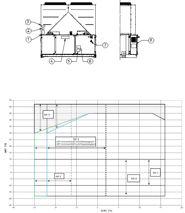
Identification de l'étiquette
1 |
– Symbole du gaz non inflammable |
5 |
– Avertissement serrage des câbles |
2 |
– Type de gaz |
6 |
– Avertissement tension dangereuse |
3 |
– Données de la plaque signalétique de l'unité |
7 |
– Symbole indiquant un danger électrique |
4 |
– Logo du fabricant |
8 |
– Instructions de levage |
Figure 2 – Limites de fonctionnement
Remarque
Le graphique en haut fournit une information indicative des limites de fonctionnement de l'intervalle. Consulter le logiciel de sélection du chiller (CSS) pour les limites de fonctionnement dans les conditions de travail pour chaque dimension.
Légende
CIAT = Température d'entrée de l'air dans le condensateur (°C)
ELWT = Température de l'eau à la sortie de l'évaporateu (°C)
A = fonctionnement avec glycol (temp. eau sortie évap. inférieure à 4°C)
B = réglage de la vitesse du ventilateur ou régulateur de vitesse nécessaire (temp. air condensation inférieure à 10°C)
C = réglage de la vitesse du ventilateur ou régulateur de vitesse nécessaire (temp. air condensation entre 10°C et -10°C)* *seulement en cas d'unités équipées de 4-5-6 ventilateurs
D = dans cette zone, les unités peuvent fonctionner à charge partielle
E = dans cette zone, la capacité minimale de l'unitépeut être supérieure à la valeur indiquée dans le tableau des caractéristiques techniques F = efficacité standard (émission acoustique standard)
G = efficacité élevée (émission acoustique standard)
D-EIMAC00804-14EU – 30/209
 Loading...