


4024.qxd 27.08.2004 16:39 Page 2
4024.qxd 27.08.2004 16:39 Page 3
MANUAL INSTRUCTION ИНСТРУКЦИЯ ПО ЭКСПЛУАТАЦИИ
ACTIVE SPEAKER SYSTEM 5.1
АКТИВНАЯ АКУСТИЧЕСКАЯ СИСТЕМА 5.1
МОДЕЛЬ VT-4024

4024.qxd 27.08.2004 16:39 Page 2
ENGLISH
SAFETY PRECAUTION
1.To avoid shock hazard or damage to the unit, do not attempt to remove the cover or the rear panel. All servicing should be referred to qualified service personnel.
2.To avoid hight heat, do not place the unit directly under the sun, and stay away from any heat source.
3.Do not expose the unit to the rain or moisture, avoid placing container with water on top of the system.
4.Please turn off the power and onplug the plug when the unit is not in use.
5.To disconnect the main plug, pull from the plug head, do not pull the power cord.
6.Avoid any loosen item drop in to the subwoofer through its ventilator.
7.Do not use harsh abrasives or chemicals to clean the unit, as it will damage the surface finish, use only a soft and damp cloth.
8.Place the unit far enough from other equipments for good heat dissipation.
2
4024.qxd 27.08.2004 16:39 Page 3
ENGLISH
BEFORE USING
Please unwrap the packing carefully, and save the packing materials for future usage.
SPEAKER
Subwoofer with built-in amplifier |
5. satellite speakers, 2 Front Speakers, 2 |
|
Rear Speakers, and 1 Center Speaker |
|
(Label on the back of each speaker) |
SPEAKER CABLE |
|
REMOTE CONTROL AND BATTERY
BATTERY INSTALLATION
1.Open the battery case.
2.Insert two batteries, do not reverse the polarity.
3.Close the battery case.
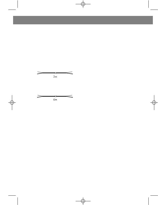
Three 2 meter speaker cables are for front and center speaker to subwoofer
Two 6 meter speaker cables are for rear speaker to subwoofer
The remote controller comes with the package helps user operates the system.
4. Kept 7 meter (23 feet), 30 degree angle when aiming at the unit.
Caution: remove the battery when the unit is not being used for a period of time.
3
4024.qxd 27.08.2004 16:39 Page 4
ENGLISH
DESCRIPTION OF THE FRONT, REAR PANEL, AND REMOTE
CONTROL
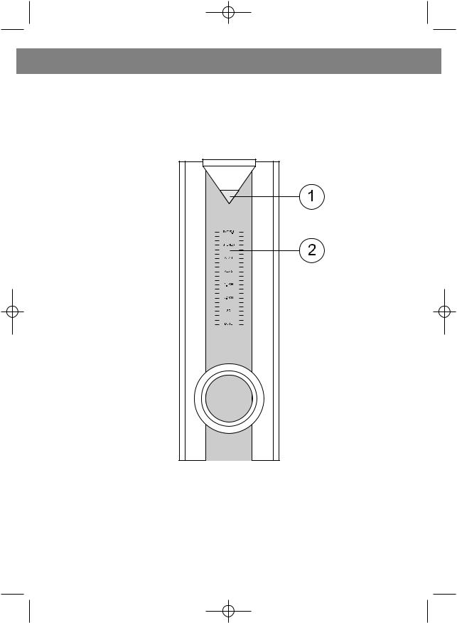
FRONT PANEL
1.Power Indicator
2.Display Panel
4
4024.qxd 27.08.2004 16:39 Page 5
ENGLISH
REAR PANEL
|
|
|
|
|
|
|
|
|
|
|
|
|
|
|
|
|
|
|
|
|
|
|
|
|
|
|
|
|
|
|
|
|
|
|
|
|
|
|
|
|
|
|
|
|
|
|
|
|
|
|
|
|
|
|
|
|
|
|
|
|
|
|
|
|
|
|
|
|
|
|
|
|
|
|
|
|
|
|
|
|
|
|
|
|
|
|
|
|
|
|
|
|
|
|
|
|
|
|
|
|
|
|
|
|
|
|
|
|
|
|
|
|
|
|
|
|
|
|
|
|
|
|
|
|
|
|
|
|
|
|
|
|
|
|
|
|
|
|
|
|
|
|
|
|
|
|
|
|
|
|
|
|
|
|
|
|
|
|
|
|
|
|
|
|
|
|
|
|
|
|
|
|
|
|
|
|
|
|
|
|
|
|
|
|
|
|
|
|
|
|
|
|
|
|
|
|
|
|
|
|
|
|
|
|
|
|
|
|
|
|
|
|
|
|
|
|
|
|
|
|
|
|
|
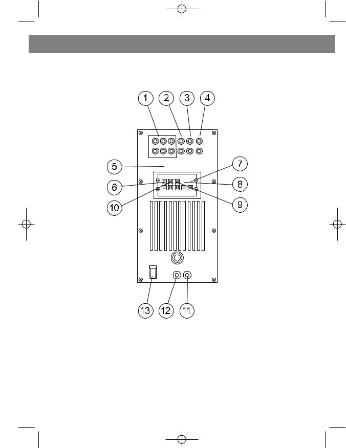
1. |
DVD/5.1 Input Connector |
|
|
9. Rear-Right Channel Output |
|||||||||||
2. |
STEREO Input Connector |
|
|
Connector |
|||||||||||
3. |
AUXl Input Connector |
|
|
10. Front-Left Channel Output |
|||||||||||
4. |
AUX2 Input Connector |
|
|
Connector |
|||||||||||
5. |
5.1 9-pin DIN Input Connector |
|
|
11.AC Power Cord |
|||||||||||
6. |
Front-Right Channel Output |
|
|
12. FUSE |
|||||||||||
|
Connector |
|
|
13. Main Power Switch |
|||||||||||
7.Center Channel Output Connector
8.Rear-Left Channel Output Connector
5
 Loading...