


VTC-TNT5RFS/2
Transcendent Series 5MP
Indoor/Outdoor WDR IP
Camera with Matrix IR LED
Illumination
QUICK START GUIDE
VITEKFEATURES
• 1/2.7” 5.0 MegaPixel CMOS Image Sensor
• Up to 30fps live view @ 5 MegaPixel (2592x1944)
• Available with 3.6mm or 2.8mm Fixed Iris Lens
• 1 Matrix Style Infrared LED with a 100’ IR Range
• Digital Wide Dynamic Range (D-WDR)
• True Mechanical Day/Night function by ICR
• XD-DNR (3D-DN & 2D-DNR) Noise Reduction
• H.265, H.264 & MJPEG Compression
• On Board Motion Detection, Privacy Masking, Region of Interest,
Exception, Line Crossing, Intrusion, Object Detection / Removal
(Museum Search)
• 1 Ch. Built-in Audio
• Remote Viewing via CMS, Internet Explorer, and iOS & Android Apps
• ONVIF Compliant
• IP67 Weather Resistance
• Optional Junction Box Mounts (VT-TJB01, VT-TJB08) and Wall Mount (VT-TWMT3) Available
• 12VDC / 1Amp & PoE (Power over Ethernet) Operation
• Available in Ivory or Charcoal Grey (VTC-TNT5RFSB/-2)
PLEASE NOTE:
Complete User Guide, Software, Tools, and Updates are available online. Scan the QR Code or visit: http://www.vitekcctv.com/Downloads
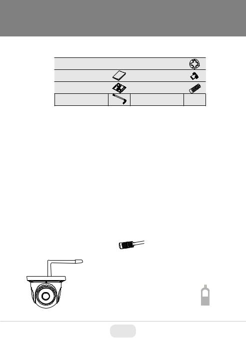
Components and Accessories
Camera |
Drill Template |
Quick Guide |
Rubber Plug |
Screws |
Waterproof Cap |
Hex Wrench |
|
Overview
2
3
4
5
1 |
1 |
Lens |
4 |
Audio Input |
2 |
RJ-45 Ethernet |
5 |
Power Input |
|
|
3 |
CVBS Output |
|
|
Network Cable/Power Connections
First connect the Waterproof Cap to an Ethernet patch cable, then connect the cameras ethernet adaptor. If not powering the camera with PoE, also connect the power Cable to an approved 12VDC Power Supply.
Network Cable
12VDC
Optional 12VDC / 1Amp
Power Connection.
Not needed with PoE
2
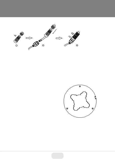
Weather Resistant Network Coupler
1.Loosen the nut from the Weather Resistant Network Coupler,
2.Run weather rated ethernet cable through coupler, then attach a RJ-45 connector.
3.Tighten the nut and coupler for a weather resistant seal.
Installation
Before beginning installation, make sure that the wall or ceiling is strong enough to withstand 3 times the weight of the camera. The mounting steps are as follows:
1. Attach the drill template to the place where you want to install the camera, then drill 3 screw holes and 1 cable hole (if you want to route the cables through the mounting base) according to the drill template
2.Route the cables and connect the power & video cables, use the rubber plug to fill the gap on the mounting base. then secure the mounting base to the ceiling or wall with screws.
3
 Loading...