VITEK VT-6403 BK User Manual [ru]

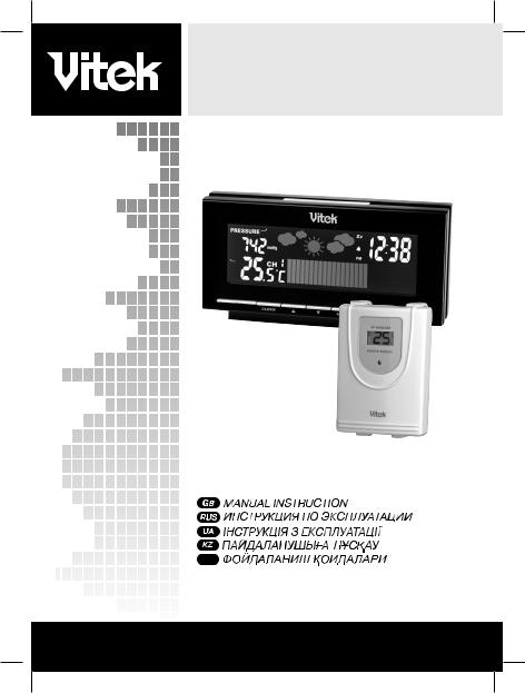
WIRELESS COLOR WEATHER STATION
MODEL VT-6403 BK
INSTRUCTION MANUAL
UZ
3
10
17
24
31
www.vitek-aus.com
6403IM.indd 1 |
19.03.2008 14:13:45 |

pic. 1
pic. 2
03IM.indd 2 |
19.03.2008 14:13:45 |

English
Meteorological station
User manual
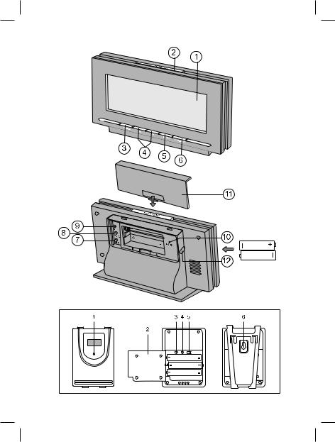
DESCRIPTION Base unit (Pic.1)
1 – LCD-display
|
Name of the |
Functions of the buttons |
|
|
button |
|
|
|
|
Pressing the button |
Press and hold the button |
|
|
|
for 3 seconds |
2 |
SNOOZE/ |
Switching on the repeat |
|
|
LIGHT |
signal and LCD-display |
|
|
|
backlight function |
|
3 |
CLOCK |
Displaying time, date |
Setting time and date |
|
▲▼ |
and day |
|
4 |
Value changing of the |
Quick value changing of the |
|
|
|
characteristic entered |
characteristic entered |
5 |
ALARM |
Displaying the time |
Setting of alarm actuation time |
|
|
set for alarm, alarm |
|
|
|
switching on/off |
|
6 |
CHANNEL |
Switching of channels |
Searching a signal from the |
|
|
importing data from |
remote sensor |
|
|
remote sensors, |
|
|
|
switching on of cyclic |
|
|
|
temperature displaying |
|
|
|
from different channels |
|
|
|
( ) |
|
7 |
MEMORY |
Displaying of maximal/ |
Reset of the registered values |
|
|
minimal registered |
|
|
|
temperature values |
|
8 |
BARO |
Switching of pressure |
Setting elevation above the sea |
|
|
measuring units |
level |
9 |
C/F |
Switching of |
|
|
|
temperature measuring |
|
|
|
units (°С/°F) |
|
10 –RESET button
11 – Battery compartment lid (for 2 batteries of “ААA” (1.5 V) type) 12 – Net adapter jack (4.5 V DC)
6403IM.indd 3 |
19.03.2008 14:13:46 |

English
Remote temperature sensor (Pic. 2)
1.LED-indicator
2.Battery compartment lid (for 2 batteries of “ААA” type)
3.Sensor re-boot button after changing channel number Тх
4.Switching button between Celsius and Fahrenheit scales C/F
5.Channel switch (1-2-3)
6.Hole for fastening units on the wall
PRECAUTIONS
1.Before operating the units, read the instruction carefully.
2.Do not immerse the units into water.
3.Do not use abrasives or substances causing damages of the body and inner parts to clean the units.
4.Do not expose the units to strong physical stress, do not subjects the units to strikes (dust and moisture are also contraindicated), as it can lead to failures and correspondingly to the reduction of life time, damages of the batteries and to the deformation of the body details.
5.Do not dismantle the unit; it will lead to the termination of the guarantee. There are no parts, requiring attention of the user inside it.
6.Use only new and specified in the manual batteries. Do not use old and new batteries together.
7.Use the net adapter supplied.
BEFORE OPERATION
Set the remote sensor within effective data transfer radius, and as close as possible to the base unit. Place the base unit and the remote sensor in places with minimal interferences for better data transfer. Take into consideration, that the data transfer radius depends on the construction material of the partitions of the building and its quantity. Try out several variants of the remote sensor and base unit placement. In spite of the fact that the remote sensor is protected from meteorological conditions, it should be set away from direct sunlight, rain or snow. House mechanisms (door bell, signal system etc.) can cause interferences for the reception of data signals from the remote sensor by the base unit. It is normal and does not influence the general operation. Transfer and reception of the data signal will resume immediately after the temporary interferences disappear.
Placing batteries in the remote sensor
1.Unscrew the screws on the battery compartment lid.
2.Select data transfer channel using the channel switch “1-2-3”.
3.Set 2 batteries (“ААА”, 1.5 V), following the polarity.
4.Close the battery compartment lid and tighten up the screws.
03IM.indd 4 |
19.03.2008 14:13:46 |

English
Connecting the net adapter to the base unit/placing batteries into the base unit
1.Using the external power supply jack, connect the net adapter to the base unit supplied (4.5 V DC).
or
2.Open the battery compartment lid.
3.Set 2 batteries (“ААА”, 1.5 V), following the polarity.
4.Close the battery compartment lid and tighten up the screws.
Note:
The base unit is intended to be powered by the external power supply; battery supply is a backup option. Constant backlight of the LCD-display is possible only while operating from the external power source through the net adapter.
Battery replacement
When the corresponding indication about battery discharge appears you should replace the batteries.
STARTING OPERATION
At the first launch of the unit, switch on the base unit first and then the remote sensor. Set the data transfer channel using the channel switch “1-2-3” on the remote sensor. Hold the CHANNEL button on the base unit, sound signal will be heard. The base unit will start searching for the signal from the remote sensor. Press the Тх button to restart the sensor. When the connection between the sensor and the base unit is established, temperature data from the remote sensor will be displayed on the LCD-display.
Setting pressure characteristics at the first launch of the unit
When connecting the base unit to the net pressure measurement units will be flashing. Use the “▼/▲” buttons to select pressure measurement units, (inHg/hPa/mBar/or mmHg). To confirm the selection press the BARO button.
1.Use the “▼/▲” buttons to set the elevation above the sea level. To confirm
the value press the BARO button.
Setting of the pressure parameters at the first launch of the unit is necessary for more exact weather forecast.
Symbol weather forecast
Weather forecast is built according to the dynamic of atmosphere pressure measuring. According to the collected data, the meteorological station can forecast weather for the next 12-24 hours.
6403IM.indd 5 |
19.03.2008 14:13:46 |

English
|
|
|
|
|
|
|
|
sunny |
partly cloudy |
cloudiness |
rain |
storm warning |
|||
Measuring precision is about 70%; more contrast weather change (for instance: from sunny weather to rain) is forecasted more precisely than insignificant (from partly cloudy to cloudy) changes.
The meteorological station forecasts possible weather that is why symbols can not correspond to the current weather. Forecast: “sunny” for a night – means unclouded sky.
For more precise forecast you should set elevation above the sea level. After restarting of the unit use the “▼/▲” buttons to select pressure measurement units. To confirm the selection press the BARO button. Use the “▼/▲” buttons to set elevation above the sea level. To confirm the selection press the BARO button.
Attention! If your meteorological station always shows “rain” or “storm warning” for a long time and does not reflect the real weather conditions, try to gradually change the elevation above the sea level (for 20 meters/60 feet) until the station indications match the weather conditions.
Increasing altitude above sea level
Decreasing altitude above sea level
TEMPERATURE INDICATIONS
The base unit can receive data signals from three remote sensors, each having corresponding channel for temperature data transfer. Units of temperature measurements can be Celsius grades or Fahrenheit grades. To select units of temperature measurements use the C/F button.
03IM.indd 6 |
19.03.2008 14:13:46 |

English
Switching data receipt channels
Press the CHANNEL button to switch data receipt channels from remote sensors (Ch 1, Ch 2, Ch 3), indoor (IN), switching on cycle displaying of temperature data from different channels ().
Temperature change tendencies
Temperature change tendencies are displayed as arrows (growing, constant, falling down) near the corresponding data.
Viewing minimal/maximal temperature value
At each press the MEM button the switching between displaying of the following parameters appears:
•Current temperature
•Minimal temperature
•Maximal temperature
Reset of the minimal/maximal temperature values
Press and hold the MEM button for more than 3 seconds to clear memory of all the channels
Note: during operation of the remote sensor at temperature below 0°C voltage in the batteries can drop, thus reducing the effective radius of its emitter.
SETTING THE DATE AND THE CURRENT TIME
The base unit can display current time and the date. To switch between the current time, date and day press the CLOCK button.
To set the current time and the date press and hold the CLOCK button for more than 3 seconds. You can select time displaying format (12 hours or 24 hours), set the current time (hours: minutes) and the date.
Use the “▼/▲” to enter the parameters. To confirm the entered parameters press the CLOCK button.
SETTING ALARM ACTUATION TIME
To switch on the alarm mode press the ALARM button. The “AL” symbol will appear on the LCD-display. To switch on/off the alarm press the button once again when the alarm is on, the symbol will appear on the LCD-display.
To set the alarm actuation time, press and hold the ALARM button. Digits of hours will start flashing. Use the “▼/▲” buttons to set the actuation hour. To confirm the setting press the ALARM button. Digits of minutes will start flashing.
6403IM.indd 7 |
19.03.2008 14:13:46 |

English
Use the “▼/▲” buttons to set actuation minutes. To confirm the setting press the ALARM button.
To switch off the alarm, press the ALARM button.
REPEAT OF ALARM SIGNAL
You can switch off the alarm signal for 10 minutes by pressing the SNOOZE/ LIGHT button. “Zz” will appear on the LCD-display. In 10 minutes the alarm signal will be repeated. To switch off the alarm, press the ALARM button.
Switching on the backlight
If the base unit is powered by the battery supply, press the SNOOZE/LIGHT button to switch on the display backlight.
TECHNICAL SPECIFICATIONS
Temperature measuring |
|
Base unit |
from 0 till +50,0°С |
|
(from +32,0 till +122,0°F) |
Remote sensor |
from -20,0 till +60,0°С |
|
(from -4,0 till +140,0°F) |
Temperature measuring precision |
0,1°С |
Data transfer from the remote sensor |
|
Data transfer frequency |
434 MHz |
Quantity of the sensors |
Max. 3 |
Operating radius |
Max. 30 m (99 feet) |
Power supply |
|
Base unit |
|
|
Net adapter 4,5 V DC, |
|
2 batteries “AАА", 1.5 V |
Remote sensor |
2 batteries "ААА", 1.5 V |
Delivery set
Base unit – 1 pc.
Remote sensor – 1 pc.
Net adapter – 1 pc.
Attention!
-Because of printing limitations display presented in these instructions may differ from the actual display in appearance.
-Manufacturer keeps right to change characteristics of the appliances without any prior announcements.
03IM.indd 8 |
19.03.2008 14:13:46 |

English
The service life of the device is no less than 3 years.
Guarantee
Details regarding guarantee conditions can be obtained from the dealer from whom the appliance was purchased. The bill of sale or receipt must be produced when making any claim under the terms of this guarantee.
This product conforms to the EMC-Requirements as laid down by the Council Directive 89/336/EEC and to the Low Voltage Regulation (23/73 EEC)
6403IM.indd 9 |
19.03.2008 14:13:46 |

Русский
Метеостанция VT-6403 Инструкция по эксплуатации
ОПИСАНИЕ Базовый блок (Рис. 1)
1.ЖК-дисплей
|
Название кнопки |
Функции кнопок |
|
|
|
Нажатие кнопки |
Нажатие и удерживание |
|
|
|
кнопки в течение 3 секунд |
2. |
SNOOZE/LIGHT |
Включение функции |
|
|
|
повтора сигнала и |
|
|
|
подсветки ЖК-дис- |
|
|
|
плея |
|
3. |
CLOCK |
Отображение вре- |
Установка времени и даты |
|
|
мени, даты и дня |
|
|
▲▼ |
недели |
|
4. |
Изменение значения Быстрое изменение значе- |
||
|
|
вводимого пара- |
ния вводимого параметра |
|
|
метра |
|
5. |
ALARM |
Отображение вре- |
Установка времени сраба- |
|
|
мени срабатывания |
тывания будильника |
|
|
будильника, вклю- |
|
|
|
чение/выключение |
|
|
|
будильника |
|
6. |
CHANNEL |
Переключение кана- |
Поиск сигнала от дистанци- |
|
|
лов приема данных |
онного датчика |
|
|
от дистанционных |
|
|
|
датчиков, включение |
|
|
|
циклического отоб- |
|
|
|
ражения данных |
|
|
|
температуры с раз- |
|
|
|
ных каналов ( ) |
|
7. |
MEMORY |
Отображение макси- Сброс зарегистрированных |
|
|
|
мальных/минималь- значений |
|
|
|
ных зарегистриро- |
|
|
|
ванных значений |
|
|
|
температуры |
|
8. |
BARO |
Переключение |
Установка высоты над уров- |
|
|
единиц измерения |
нем моря |
|
|
давления |
|
10
03IM.indd 10 |
19.03.2008 14:13:46 |

Русский
9. C/F |
Переключение еди- |
|
ниц измерения тем- |
|
пературы (°С/°F) |
10.кнопка сброса (RESET)
11.крышка батарейного отсека (для двух батареек типа «ААА», 1.5 В)
12.гнездо для подключения сетевого адаптера (4,5 В DC)
Дистанционный датчик температуры (Рис. 2)
1.светодиодный индикатор
2.крышка батарейного отсека (для двух батареек типа «AАА»)
3.кнопка перезапуска датчика после смены номера канала (Тх)
4.кнопка переключения между шкалами по Цельсию и Фаренгейту (°С/°F)
5.переключатель каналов (1-2-3)
6.отверстие для крепления устройства к стене
МЕРЫ ПРЕДОСТОРОЖНОСТИ
1.Прежде чем начать работу с приборами, внимательно прочитайте инструкцию по эксплуатации.
2.Не погружайте приборы в воду.
3.Не чистите приборы абразивными средствами и веществами, вызывающими повреждение корпуса и внутренних частей.
4.Не подвергайте приборы сильным физическим воздействиям, ударам (пыль и влага также противопоказаны), так как это может привести к появлению неисправностей и, соответственно, к сокращению срока службы, повреждению батареек и к деформированию деталей корпуса.
5.Не разбирайте прибор, это приведет к снятию с гарантии. Внутри прибора нет деталей, требующих внимания пользователя.
6.Используйте только новые батарейки и именно такие, как указано в инструкции по эксплуатации. Не устанавливайте одновременно новую и старую батарейки.
7.Используйте только тот сетевой адаптер, который входит в комплект поставки.
ПЕРЕД НАЧАЛОМ РАБОТЫ
Установите дистанционный датчик в пределах радиуса эффективной передачи данных, и как можно ближе к базовому блоку. Размещайте базовый блок и дистанционный датчик в местах с минимальными помехами для наилучшей передачи данных. Примите во внимание, что радиус передачи данных дистанционного датчика зависит от строительного материала пе-
11
6403IM.indd 11 |
19.03.2008 14:13:46 |

Русский
регородок помещения и их количества. Попробуйте несколько вариантов размещения дистанционного датчика и базового блока. Несмотря на то, что дистанционный датчик защищен от воздействия погодных условий, его необходимо установить так, чтобы на него не попадали прямые солнечные лучи, дождь или снег.
Домашние устройства (дверной звонок, сигнализация и т.д.) могут создавать помехи при приеме базовым блоком сигнала данных от дистанционного датчика - это нормальное явление, и не влияет на общую работу. Передача и прием сигнала данных возобновится сразу после исчезновения временных помех.
Установка батареек в дистанционный датчик
1.Открутите винты на крышке батарейного отсека.
2.Выберите канал передачи данных с помощью переключателя каналов
«1-2-3».
3.Установите 2 батарейки («ААА», 1.5 В), соблюдая полярность.
4.Закройте крышку батарейного отсека и закрутите винты.
Подключение сетевого адаптера к базовому блоку/установка батареек в базовый блок
1.Используя гнездо для подключения внешнего источника питания, под-
соедините к базовому блоку сетевой адаптер, входящий в комплект поставки (4,5 В DC),
или
2.Откройте крышку батарейного отсека.
3.Установите 2 батарейки («ААА», 1.5 В), соблюдая полярность.
4.Закройте крышку батарейного отсека.
Примечание
Базовый блок предназначен для работы от внешнего источника питания, работа от батареек является резервным вариантом. Постоянная подсветка ЖК-дисплея возможна только при работе от внешнего источника через сетевой адаптер.
Замена батареек
При появлении соответствующей пиктограммы о разрядке батареек следует заменить батарейки.
Начало работы
При начальном запуске прибора сначала включите базовый блок, а затем
12
03IM.indd 12 |
19.03.2008 14:13:46 |
 Loading...