


VITEK
VT-EH Series
4, 8, and 16 Channel Digital Video Recorders with H.264 Compression
•4, 8, or 16 Video Inputs with 1 Main, 1 Spot Monitor Output and 1 DVI output (VGA compatible with included adaptor)
•H.264 Compression
•Supports both Dynamic and Static IP Addresses
•4 Alarm Inputs / 1 Relay Out
•Up to 480fps Live Display & 480fps Recording (VT-EH16) / 240/240 (VT-EH8) / 240/240 (VT-EH4)
•Remote Viewing over the Internet, LAN, Explorer, Safari, Firefox, Opera (Blackberry) & Chrome
•Applications for iPhone, iPad, iTouch and Droid Devices
•Supports two internal Hard Drives
•500GB to 4TB Internal Storage Options (up to 4TB @ 2x2TB)
•“Quick Search” Function for automatic review
•Email Event Notification with Snapshot
•CMS Central Management Software (Included)
•MAC Client Software (Included)
•Automatic sending of Health and Event notifications via email
•4 Audio Inputs & 1 Output
•Control locally via Front Panel, USB Mouse or with the Included IR Remote Control
•PTZ Control over RS-485
•Backup via Ethernet, FTP or USB
•Built-In Bandwidth Throttling
•Rack Kit “Ears” Available (VT-E RK)
VT-EH Series DVRs________________________________________________________________________________
IMPORTANT SAFETY INSTRUCTIONS
1)Read these instructions.
2)Keep these instructions.
3)Heed all warnings.
4)Follow all instructions.
5)Do not use this apparatus near water.
6)Clean only with a dry cloth.
7)Do not block any of the ventilation openings. Install in accordance with the manufacturer's instructions.
8)Do not install near any heat sources such as radiators, heat registers, stoves, or other apparatus that produce heat.
9)Understand the safety purpose of a polarized or grounding type plug.
A polarized plug has two blades with one wider than the other.
A grounding type plug has two blades and a third grounding prong.
The wide blade or the third prong is provided for your safety.
When the provided plug does not fit into your outlet, consult an electrician for replacement of the obsolete outlet.
10)Protect the power cord from being walked on or pinched particularly at plugs, convenience receptacles, and the point where they exit from the apparatus.
11)Only use the attachments/accessories specified by the manufacturer.
12)Use only with a cart, stand, tripod, bracket, or table specified by the manufacturer, or sold with the apparatus.
When a cart is used, use caution when moving the cart/apparatus combination to avoid injury from tip-over.
13)Unplug this apparatus during lightning storms or when unused for long periods of time.
14)Refer all servicing to qualified service personnel. Servicing is required when the apparatus has been damaged in any way including a damaged power supply cord or plug, if liquid has been spilled or objects have fallen into the apparatus, the apparatus has been exposed to rain or moisture, does not operate normally, or has been dropped.
15)This equipment is for indoor use and all the communication wirings are limited to use inside of the building.
16)The socket-outlet shall be installed near the equipment and shall be easily accessible.
17)CAUTION
RISK OF EXPLOSION IF BATTERY IS REPLACED WITH AN INCORRECT TYPE.
DISPOSE OF USED BATTERIES ACCORDING TO THE INSTRUCTIONS.
#Operation Max temperature: 40ºC/104ºF
#USB Load condition: USB Ports (5VDC, Max. 500 mA)
2
VT-EH Series DVRs________________________________________________________________________________
BEFORE INSTALLATION
●Installation should only be carried out by qualified personnel and in accordance with up-to-date electrical regulations.
●The DVR must be placed on a stable surface or mounted in an approved cabinet. Adequate ventilation must be provided, taking particular care not to block any of the air vents on the DVR.
●Adequate protection against lightning and power surges must be installed to prevent damage to the DVR.
●Any safety warnings on the DVR and in these instructions must be adhered to.
●If cleaning is necessary, shutdown the DVR and disconnect power first.
Use only a soft, dry cloth and never use any abrasive cleaners.
●Do not attempt to service or repair the DVR as opening or removing covers may expose dangerous voltages or other hazards. Refer all servicing to qualified service personnel.
3
VT-EH Series DVRs________________________________________________________________________________
MAIN FEATURES
MOUSE CONTROL
Designed to be easily controlled with a mouse.
ENHANCED GRAPHICAL USER INTERFACE [GUI]
The DVR menu structure and on screen display is presented in a simple to use and logical GUI format.
GENUINE PENTAPLEX OPERATION
The DVR will continue to record at full frame rate during local playback, local setup, multi user remote viewing and playback and remote setup.
AUDIO
4 audio inputs are supported which can be assigned to any video channel. Live and recorded audio can be monitored remotely over the internet and remote ‗talkback‘ audio transmission to the DVR is also possible.
BACKUP
Recorded footage (including audio) can be archived to a USB memory stick or to your computer through network connection.
Playback software is embedded with the backup files. The backup also contains the system event log and backup log for full traceability.
REMOTE CONNECTION
Depending on the user level, full DVR control is available over the internet as well as the ability to remotely configure the DVR. Alarm outputs on the DVR can be remotely triggered over the internet.
COMPREHENSIVE RECORDING SETUP
Recording can be scheduled, alarm or motion activated. For each type of recording, frame rates, image quality and audio recording properties can be adjusted per hour, day and for each individual channel.
The DVR also has a panic recording feature (from the front panel or external input) which overrides all other recording settings to provide the best quality recording in the event of an emergency.
PTZ CONTROL
Full PTZ control is available from the front panel or remote connection and a wide number of speed dome protocols are supported. Protocols can be set individually for each channel and PTZ speed can be adjusted to suit particular speed domes.
4
VT-EH Series DVRs________________________________________________________________________________
TELEMETRY CONTROL
Full telemetry control is available from the front panel or remote connection and a wide number of speed dome protocols are supported. Protocols can be set individually for each channel and telemetry speed can be adjusted to suit particular speed domes.
EXTENSIVE MONITOR SUPPORT
The DVR has 2 main monitor outputs (Composite and DVI).
One spot monitor output can be programmed in the DVR setup.
LIVE DISPLAY
The DVR displays single or multi screen images and also has several sequence modes (standard and user definable).
CONFIGURATION BACKUP
All configuration settings on the DVR can be saved to USB memory stick or a PC file remotely.
The saved data can then be uploaded to other DVR units allowing rapid deployment where more than one DVR is being installed.
EMAIL SUPPORT
The DVR can send emails to specific users to notify events such as alarm, motion detection, hard drive failure, & etc.
5
VT-EH Series DVRs________________________________________________________________________________
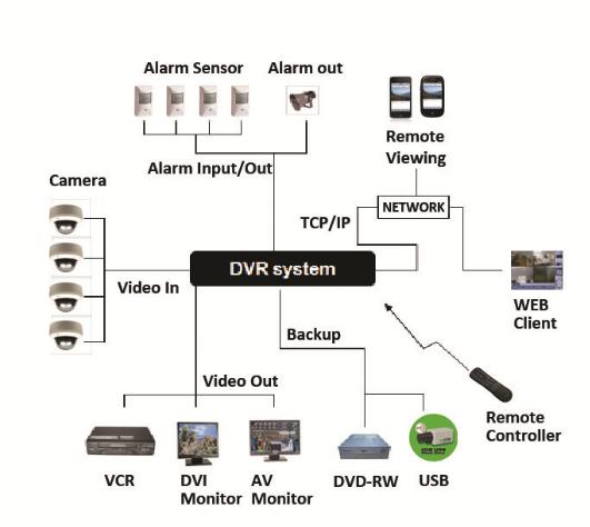
SYSTEM ORGANIZATION
6
VT-EH Series DVRs________________________________________________________________________________
SYSTEM CONFIGURATION
1. Front panel description
KEY |
DESCRIPTION |
|
|
|
|
|
|
Function Keys |
|
|
|
POWER |
|
Turns unit On/Off |
|
|
|
DISPLAY |
|
Selects various display modes in live display and playback |
|
|
|
SCR MODE |
|
Change display mode/Split mode |
|
|
|
SEARCH |
|
Displays the search menu |
|
|
|
MENU |
|
Displays the setup menus |
|
|
|
|
|
Control Keys |
|
|
|
CURSOR KEYS |
|
Navigates the menu system |
|
|
|
ENTER |
|
Apply settings or Select an item |
|
|
|
RETURN |
|
Cancel or go to Previous menu |
|
|
|
|
|
Playback Controls |
|
|
|
|
|
Increases reverse playback speed |
|
|
|
|
|
Selects reverse playback |
|
|
|
ΙΙ |
|
Pauses / resumes playback |
|
|
|
|
|
Selects forward playback and also accesses the instant playback feature |
|
|
|
|
|
Increases forward playback speed |
|
|
|
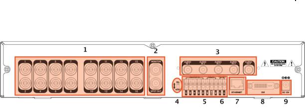
2. Rear panel description
7
VT-EH Series DVRs________________________________________________________________________________
1. CAMERA INPUTS
Connect up to 16 camera inputs.
2. MAIN MONITOR / SPOT MONITOR OUTPUTS
Connect AV monitor instead of VGA output / One spot monitor can be connected.
3. AUDIO INPUTS & OUTPUTS
Up to 4 audio inputs and one audio output can be connected.
4.PAL/NTSC SWITCH
5.ALARM INPUTS & RELAY OUTPUT
Up to 4 alarm inputs can be connected and configured as high or low inputs with common ground.
One Relay output can be connected and configured as high or low with common ground Connection to external telemetry.
6.RS-485 – devices for PTZ or Keyboard controller
7.LAN - LAN connection to a router or internal network
8.DVI
DVI main monitor connection to a PC monitor or plasma screen.
Through DVI to VGA convertor, User can connect VGA port device as monitor.
9. DC POWER– connection 12V/5A adaptor
8
VT-EH Series DVRs________________________________________________________________________________
SYSTEM CONFIGURE – Remote Controller
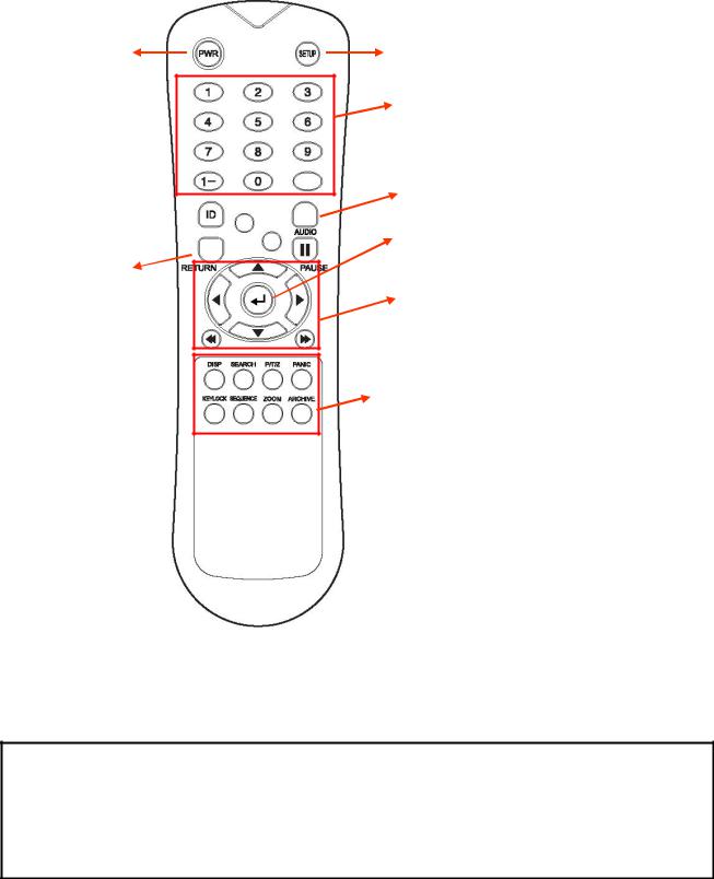
3. Remote Controller description.
POWER
System
ON/OFF
ID Button
Select DVR ID 
ID
RETURN
Cancel / Deselect
Previous Screen
SETUP: Open System Setup Menu
Channel Selection Buttons
AUDIO: Not Supported
ENTER: Apply / Select / Go to Next Screen
Navigation Buttons:
Used for Playback Control, Menu Navigation, and PTZ/Focus Control
DISP: Change display screen.
SEARCH: Go to Search mode.
PTZ: Go to PTZ menu.
PANIC: Record by Panic setting.
KEYLOCK: Lock the keys (Remote / Front)
SEQUENCE: Change to Sequence screen.
ZOOM: Go to Zoom mode.
ARCHIVE: Go to backup menu.
If there are many DVRs on a stack, each DVR must be set with a different ID. You can do this here:
Menu/System Setup/Main/System/Control Device. From the remote controller sync the remote to each DVR, then all DVRs can be controlled with one remote controller.
How to sync a remote controller to a DVR’s ID
Press the ID button on the remote. Notice REMOTE ID statement on the screen.
On the remote controller, enter the System ID number, press ENTER, then press RETURN. (default System ID is 0)
9
VT-EH Series DVRs________________________________________________________________________________
CONNECT & POWER ON
•Connect up to 16 CAMERA INPUTS as necessary.
•Connect monitors to the DVR using the COMPOSITE or DVI connections.
•Connect power to the DVR. The DVR checks for proper power connection and emits two beeps. Press the POWER BUTTON on the front panel of the DVR to begin operation.
1 Disk is Found
Internal Disk Size: 244GB
External Disk Size: 0GB
… … … … … … … … … … … … … … …
The DVR startup screen detects and checks the status of hard drive(s).
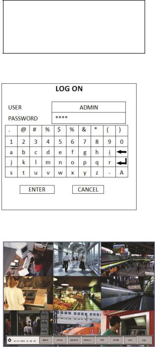
After startup diagnostics are complete, the operator must logon to the system. The default user name is ‗ADMIN‘.
Using the CHANNEL SELECTION buttons, key in
the default password of ‗1234‘ and press the ENTER button.
The DVR begins normal operation and shows the default display of all 4, 8 or16 channels depending on system model.
The status bar (Include menu control) at the bottom of the screen shows menu first time. After that, it will show the current time and date.
A title for each channel is shown.
The red square and letter ‗C‘ in the top right of each channel display shows that the channel is recording in Continuous mode.
10
VT-EH Series DVRs________________________________________________________________________________
MENU CONTROL
All menus can be controlled from the above ‗Status Bar‘ with the mouse or front buttons.
LIVE DISPLAY
DIVISION SCREEN
Select the ‗DISPLAY‖ button for the screen division menu to appear.
Select the screen type (1, 4, 6, 8, 9, 16 and rotation sequence).
Sequence mode
User can select the type from display menu.
Press the SEQ button. Each channel is shown in full screen for a set period of time before switching to the next channel.
To stop the sequence on a particular channel, press the SEQ button again.
More complex sequences can be programmed through the setup menu.
11
VT-EH Series DVRs________________________________________________________________________________
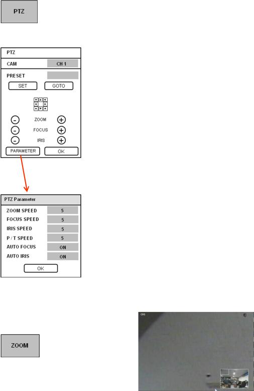
LIVE DISPLAY
1) CAM: Select the Channel.
2) |
Preset: Input preset numbers 1~255. |
||
|
|
|
Click SET to save current view (camera position) as a preset. |
|
|
|
Click GOTO to move the camera to a saved preset position. |
3) |
Zoom, Focus, IRIS: User can control each item with + or - button. |
||
4) |
Parameter: Press this button and another window will appear. |
||
|
|
|
User can view each item from PTZ parameter menu. |
. |
|
|
(Parameter values can be set in CAMERA: PTZ SETUP) |
|
|
||
|
|
|
|
Digital Zoom
Select the ―ZOOM‖ button.
When viewing a channel in full screen, the operator can zoom in to a particular area by up to 8 times. To use the digital zoom, select the required channel and press the ZOOM button.
The small window at bottom right shows the full image and the main display area shows the zoomed portion. Use and keys to zoom in/out.
12
VT-EH Series DVRs________________________________________________________________________________
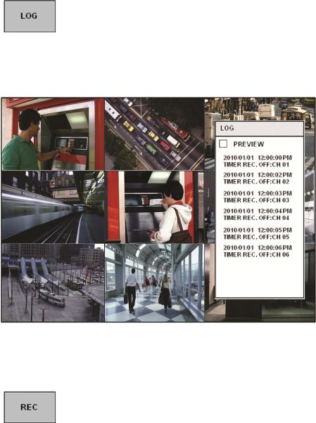
LIVE DISPLAY
User can see the current log immediately.
Click once after selecting log, recorded data will be played. This will appear if you select the ―PREVIEW‖ option.
Panic Recording
This menu is used to start and stop the Panic recording.
If panic recording is started, the record icon will change to a red square with a ―P‖.
Select once more to return to previous.
- Panic recording setup will be assigned from Record menu.
13
VT-EH Series DVRs________________________________________________________________________________
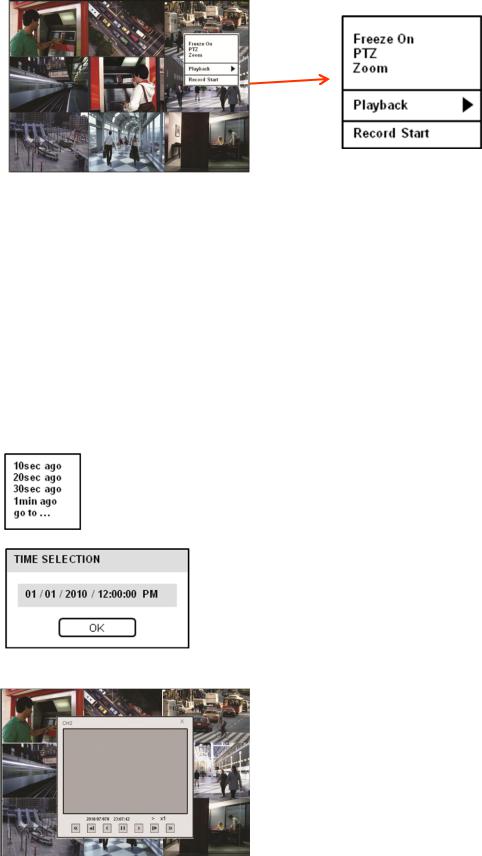
LIVE DISPLAY
Quick Menu
User can use quick menu by right-clicking the mouse on each live channel.
1.Freeze On/Off: User can stop the live display of a channel that the user wants. Even though other channels show live display, this particular channel display is stopped. Click once more to return to previous.
2.PTZ
Please refer to ―PTZ‖ menu on Page 12.
3.Zoom
Please refer to ―ZOOM‖ menu on Page 12.
4. Playback
User can playback immediately with selected time (10, 20, 30 seconds or 1 minute ago).
In case of selecting ―go to‘‖ menu, this menu will appear.
After selecting the time, press ―OK‖.
5. Record Start (Stop)
Please refer to ―Panic record‖ menu on Page 13.
14
VT-EH Series DVRs________________________________________________________________________________
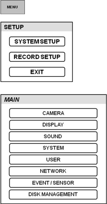
SYSTEM SETUP
Click ―MENU‖ and click the SYSTEM SETUP menu.
To navigate around any items in the setup menu, use the CURSOR KEYS and the ENTER and RETURN buttons.
In general, the ENTER button is used to select and change a particular item and the RETURN button is used to cancel a change or exit from a particular setup screen.
To setup all main system functions, highlight SYSTEM SETUP and press ENTER.
15
VT-EH Series DVRs________________________________________________________________________________
SYSTEM SETUP
CAMERA
Click the CAMERA menu.
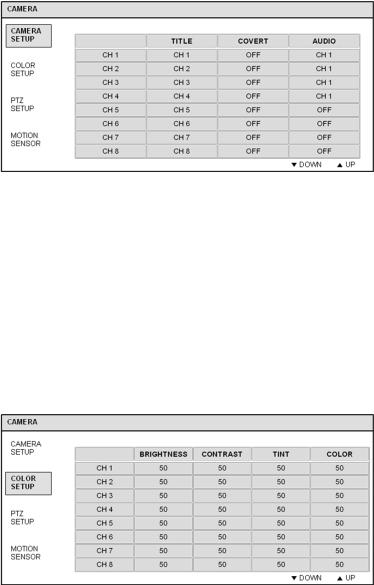
CAMERA: CAMERA SETUP
To setup the various camera options, highlight CAMERA and press ENTER.
TITLE: Input the camera title.
COVERT: When it is set to ON, the camera image is not displayed in live display but continues to record.
AUDIO: Determines the audio recording channel.
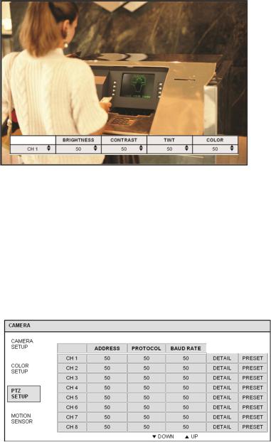
CAMERA: COLOR SETUP
Brightness, contrast, tint and color can be adjusted for each individual channel.
Highlight each channel to modify and press ENTER.
16
VT-EH Series DVRs________________________________________________________________________________
SYSTEM SETUP
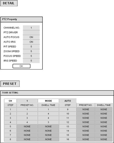
Click each value with  button.
The selected channel is displayed in full screen.
BRIGHTNESS, CONTRAST, TINT and COLOR can be changed as necessary.
To modify a different channel, highlight CAMERA and choose the desired channel.
Press RETURN when all changes are complete.
CAMERA: PTZ SETUP
ADDRESS: The unique ID of the PTZ device.
PROTOCOL: The protocol of the PTZ device.
BAUD RATE: The baud rate of the PTZ device.
DETAIL: Detail setting for PTZ device. (Refer to the next page)
PRESET: Tour setting for PTZ device. (Refer to the next page)
Click the PTZ SETUP menu and click each value on the ADDRESS, PROTOCOL and BAUD RATE menu.
Change each value with  button.
17
VT-EH Series DVRs________________________________________________________________________________
SYSTEM SETUP
VITEK XPRESS
Click the ―DETAIL‖ button and change the detail value with  button.
Note that some settings, such as AUTO FOCUS, may not be compatible with particular PTZ equipment.
If this is the case, changing the value will have no effect on PTZ control.
Click the ―TOUR‖ button and set the MODE to [AUTO] to use TOUR function.
First, please set PRESET number on the live PTZ mode.
Then set the PRESET number from 1 to 16 and DWELL Time.
DWELL TIME is the time spent in one position until you move to the next preset position.
18

VT-EH Series DVRs________________________________________________________________________________
SYSTEM SETUP
CAMERA: MOTION SENSOR
Click the MOTION SENSOR menu and click the value on the SENSITIVITY menu.
Change the value with  button.
SENSITIVITY: Between 1 (Lowest) and 10 (Highest) and determines the degree of motion required before recording is activated.
Click the AREA SETUP button.
AREA SETUP: Choosing this option allows the operator to define which areas of the image are monitored for motion detection.
To quick select or deselect the entire grid, click the right mouse button and click the SELECT ALL or DESELECT ALL menu.
-Blank/clear area: Non selected area
-White grid-like boxes: Selected area
19
VT-EH Series DVRs________________________________________________________________________________
SYSTEM SETUP
DISPLAY
To setup the various display options, highlight DISPLAY and press ENTER.
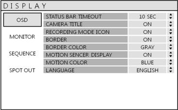
DISPLAY - OSD
Click the OSD menu.
Then click the  button for ON/OFF and change the value.
STATUS BAR: Determines the time to turn from the menu of status bar to time display.
CAMERA TITLE: Determines whether the camera title is displayed.
RECORDING MODE ICON: Determines whether the DVR recording status is shown at the top right of each channel display window.
BORDER: Determines whether there is a border around each channel in multi screen display mode.
BORDER COLOR: If the border is ON, the operator can choose the color.
MOTION SENSOR DISPLAY: If false motion recording is occurring, the operator can use this feature to determine and rectify the cause in real-time.
OFF – normal display mode.
ON – areas where motion is detected are highlighted with colored blocks.
MOTION COLOR: The color of the blocks displayed when MOTION SENSOR DISPLAY is set to ON.
LANGUAGE: Determines the language type.
20
VT-EH Series DVRs________________________________________________________________________________
SYSTEM SETUP
DISPLAY: MONITOR
Click the MONITOR menu
Then click the  button for ON/OFF and to change the value.
SEQUENCE DWELL: The time each screen is displayed in a sequence operation.
SPOT DWELL: The time each screen is displayed on the spot monitor outputs.
DE-INTERLACE MODE: When recording any channels in D1 resolution (704 x 576), this should be set to ON to prevent shudder during playback.
ALARM POP-UP MODE: When set to ON, an alarm input will cause the associated channel to display in full screen.
ALARM POP-UP DWELL: Determines how long the full screen popup is displayed after an alarm input. If the alarm condition continues, the popup screen is displayed constantly.
MOTION POP-UP MODE: When set to ON, motion detection will cause the associated channel to display full screen.
MOTION POP-UP DWELL: Determines how long the full screen popup is displayed after motion detection. If motion continues, the popup screen is displayed constantly.
21
VT-EH Series DVRs________________________________________________________________________________
SYSTEM SETUP
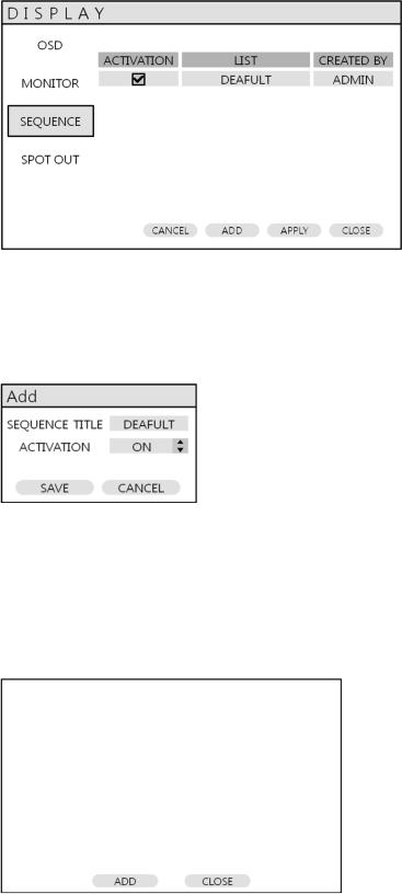
DISPLAY: SEQUENCE
Click the SEQUENCE menu.
When the SEQ button is pressed, the default sequence will cycle through all channels, one by one.
Sequence setup allows the operator to define a custom sequence, using mixed multi screen views and any desired channels.
Click the ADD menu.
To add a new sequence, highlight ADD and press ENTER.
Sequence title is highlighted – press ENTER to bring up the virtual keyboard and key in a name or reference number for the new sequence.
Select the SAVE. Then, the menu below will appear.
22
VT-EH Series DVRs________________________________________________________________________________
SYSTEM SETUP
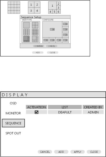
Press ADD. Then, ―Sequence Setup‖ menu appears.
Determine the ―VIEW TYPE‖ and assign ―CONFIGURE‖. Then, click CONFIRM.
To add an additional mode, click ADD. After finishing the setup, press CLOSE.
To modify the current one, double click that mode. Then ‗Sequence Setup‖ window will appear again.
The new sequence is now saved and can be started by pressing the SEQ button when in live view.
23
VT-EH Series DVRs________________________________________________________________________________
SYSTEM SETUP
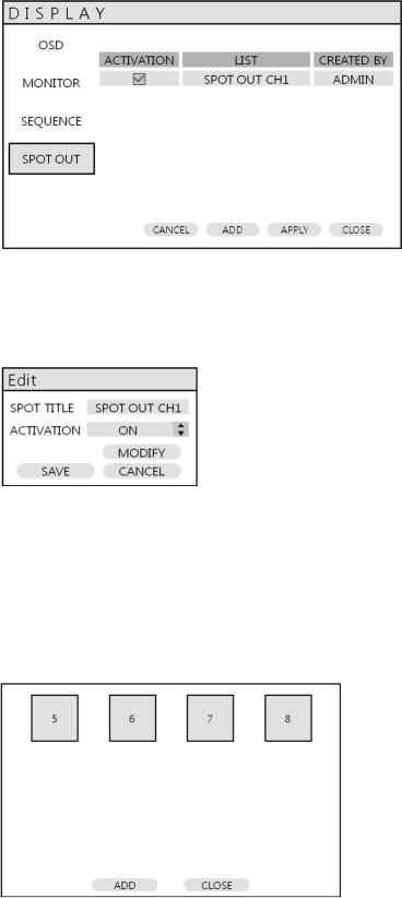
DISPLAY: SPOT-OUT
Click the SPOT-OUT menu and click the camera channel for ON/OFF.
The DVR has 1 SPOT MONITOR OUTPUT.
User can assign the SPOT OUT display for each channel.
Double click the spot out channel that needs to be assigned.
SPOT TITLE: input the title.
ACTIVATION: Determines ON/OFF.
Press MODIFY. (Below is default setup)
To modify the current display, double click the display. Then ‗Spot Sequence Setup‖ window will appear.
How to setup is the same as Sequence setup. (User can assign Single and Quad display only.) To add the additional display, press ADD.
24
VT-EH Series DVRs________________________________________________________________________________
SYSTEM SETUP
SOUND
Click the SOUND menu.
To setup the various sound options, highlight SOUND and press ENTER
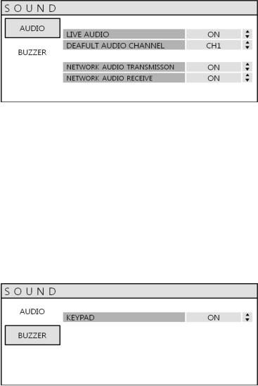
SOUND: AUDIO
Click the AUDIO menu and click the ON/OFF menu.
Then, click the  button for ON/OFF.
LIVE AUDIO: When it is set to ON, the selected audio channel can be monitored on the AUDIO OUTPUT.
AUDIO MONITORING CHANNEL: Specify which one of the 4 AUDIO INPUTS is routed to the AUDIO OUTPUT.
NETWORK AUDIO TX: When set to ON, live and playback audio is transmitted to a remote PC connection.
NETWORK AUDIO RX: When set to ON, allows a remote PC connection to send audio back to the DVR.
SOUND: BUZZER
Click the BUZZER menu and click the ON/OFF menu.
Then, click the  button for ON/OFF.
KEYPAD: When it is set to ON, each front panel button press is confirmed by a beep.
25
 Loading...