


АУДИО-ВИДЕО И БЫТОВАЯ ТЕХНИКА
VT-6405
WEATHER STATION
МЕТЕОСТАНЦИЯ
Инструкция по эксплуатации
|
Manual instruction |
4 |
GB |
||
|
|
|
|
Инструкция по эксплуатации |
12 |
RUS |
||
|
|
|
|
Інструкція з експлуатації |
22 |
UA |
||
|
|
|
|
Пайдалану нұсқасы |
32 |
KZ |
||
|
|
|
|
Фойдаланиш қоидалари |
41 |
UZ |
www.vitek.ru
6405IM.indd 1 |
12.11.2008 11:21:12 |

pic.1
5IM.indd 2 |
12.11.2008 11:21:12 |
pic.2
6405IM.indd 3 |
12.11.2008 11:21:12 |
English
Weather station VT-6405
Please read these instructions carefully before connecting, operating or adjusting the unit. Follow all warnings and operating recommendations in this manual. Keep this manual for future reference.
ATTENTION!
Risk of electric shock! DO NOT OPEN!
Warning:
To prevent fire or shock hazard do not expose the appliance to rain or moisture. To prevent shock hazard do not remove the cover yourself.
Apply to a service centre for repair and maintenance.
This lightning flash with arrowhead symbol, within an equilateral triangle, is intended to alert the user to the presence of uninsulated “dangerous voltage” within the product’s enclosure that may be of sufficient magnitude to constitute a risk of electric shock to persons.
The exclamation point within an equilateral triangle is intended to alert the user to the presence of important operating and maintenance(servicing)instructionsinthemanualaccompanying the appliance.
PRECAUTIONS
1.Before operating the units, read the instruction carefully.
2.Do not immerse the units into water.
3.Do not use abrasives or substances causing damages of the body and inner parts to clean the units.
4.Do not apply hard efforts to the units, do not subjects the units to strikes (dust and humidity are also contraindicated), as it can lead to failures and correspondingly to the reduction of life time, damages of the batteries and to the deformation of the body details.
5.If you break the unit; it will lead to the ending of guarantee. There are no details, demanding attention of the user inside it.
6.Use only new and specified in the manual batteries. Do not use old and new batteries together.
7.While long operation of the sensor in the conditions of extreme temperatures, the voltage of its batteries can be lowered, the operation radius of the remote sensor will be reduced.
5IM.indd 4 |
12.11.2008 11:21:12 |

English
DESCRIPTION
Basic unit (pic.1)
1.Display
2.The SNOOZE button - Switching on the LCD-display signal and
backlight repeat function
3, 5.the +/- buttons - Value changing of the entering characteristic
4.The MODE button – switching between display sectors,
confirmation of the value
6,8. The AL1, AL2 buttons - Displaying of alarm actuation, alarm switching on/off
7.The °С/°F buttons - Switching of
temperature units
9.Hole for fastening of the unit on the wall
10.The CHANNEL button - Switching of channels importing data from remote sensors
11.The ▼/SEARCH button - Searching a signal from the remote sensor
12.The UNIT button - Selecting pressure measuring units
13.The ▲/MEMORY button - Displaying of maximal/minimal temperature values registered by the basic unit and the remote sensor
14.The PRESSURE/ALTITUDE button
– Displaying of pressure/altitude values and entering the setup mode
15.The RESET button
16.Battery compartment lid (for 2 batteries “АА”)
17.Table support
18.Net adapter jack (DC7,5 V)
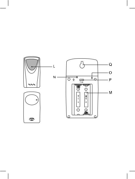
Remote temperature sensor (pic.2)
L.LED on Front Panel
When device is transferring data, LED blinks one time.
When battery replacement is required, LED blinks two times.
M.Battery Compartment Compartment is intended for 2 batteries of UM-3 or АА type.
N.Reset Button (RESET) This button is used to reset
sensor after changing channel number.
O.Button for switching between Celsius/Fahrenheit scale
P.Channels switch (CHANNEL) This button is used for selecting channel of data transfer before batteries installation.
Q.Hole for Mounting Device to Wall
BEFORE OPERATION
For proper operation of the unit insert the batteries firstly into the battery compartment and then into the base unit. Set the remote sensor within effective data transfer radius, and as close as possible to the base unit. Place the based unit and the remote sensor in places with minimal interferences for better data transfer. Take into consideration, that the data transfer radius depends on the construction material of partitions of the building and its quantity. Try out several variants of the remote sensor and base unit allocation. In spite of the fact that the remote sensor is protected from meteorological conditions, it should be set in a way that direct sun-
6405IM.indd 5 |
12.11.2008 11:21:12 |

English
light, rain or snow does not get it. House mechanisms (door bell, signal system etc.) can cause interferences while reception by the base unit of data signals from the remote sensor. It is normal and does not influence the general operation. Transfer and reception of the data signal will resume immediately after the temporary interferences disappear.
Placing batteries in the remote sensor
1.Unscrew the screws on the battery compartment lid.
2.Select data transfer channel using the channel switch.
3.Set 2 batteries, following the polarity.
4.Close the battery compartment lid and tighten up the screws.
Connecting the net adapter to the base unit/placing batteries into the base unit
1.Open the battery compartment lid.
2.Set 2 batteries (“ААА”, 1.5 V), following the polarity.
3.Close the battery compartment lid and tighten up the screws
4.Make sure that the adapter voltage corresponds to the voltage in the mains.
5.Using the external power supply jack, connect the net adapter to the base unit supplied (7,5 V DC).
Note:
The base unit is intended to be pow-
ered by the external power supply; battery supply is a backup variant. If the net adapter is disconnected
from the base unit, the following symbol will appear on the display ( )
)
Battery replacement
When the corresponding indication about battery discharge appears you should replace the batteries.
Note: While long operation of the remote sensor at high or low temperatures, its voltage can lower, reducing thus the operating radius of its transmitter.
STARTING OPERATION
After inserting of the batteries in the remote control, it will start data transfer (temperature and humidity) with about 45 second intervals. In about two minutes after inserting of the batteries in the base unit or connecting to the mains, it will start in its turn searching of a signal from the remote control. In ten minutes after receiving data, they will appear on the display of the base unit. Data updating is performed automatically in 45 seconds.
If there is no signal from the remote sensor, the “--“symbols will appear on the display.
For synchronization of the base unit and the remote sensor press and hold the ▼/SEARCH button during 2 seconds.
Note: Repeat this procedure, if the registrations of the remote sensor differ from those of the base unit.
5IM.indd 6 |
12.11.2008 11:21:13 |
English
Setting pressure characteristics at first launch of the unit
1.When connecting the base unit to the net pressure units “hPa/mBar” will appear on the display.
2.Use the ▼/SEARCH or ▲/MEMORY buttons to select pressure units (hPa/mBar/, inHg, mmHg). To confirm the selection press the PRESSURE/ ALTITUDE button.
3.The “0” and the “meter” will appear on the display. Use the ▼/SEARCH or ▲/MEMORY buttons to select the altitude units. To confirm the selection press the PRESSURE/ALTITUDE button.
4.The “10” symbols will appear on the display, if meters or “33” is selected as altitude units, if “foot” is selected as altitude units. Use the ▼/SEARCH or ▲/MEMORY buttons to set altitude. To confirm the selection press the PRESSURE/ALTITUDE button.
Note: Setting of the pressure parameters at first launch of the unit is necessary for more exact weather forecast. Default settings (in no settings are made during 60 seconds): pressure units: hPa/mBar, mmHg, altitude units – meters, altitude – 10 meters.
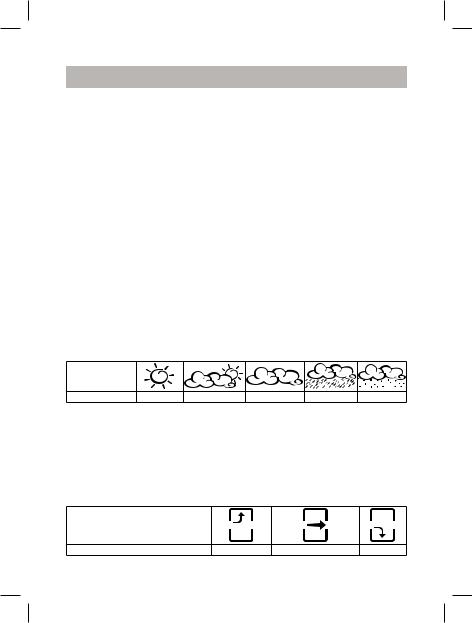
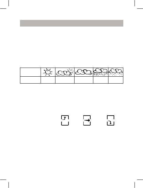
Symbolic weather forecast
Weather forecast is built according to the dynamic of atmosphere pressure measuring. According to the collected data, the meteorological station can forecast weather for the next 12-24 hours.
Display symbol
Forecast |
sunny Partly cloudy |
cloudy |
rain |
snow |
Measuring precision is about 70%. The meteorological station forecasts possible weather that is why symbols can not correspond to the current weather. Forecast: “sunny” for a night – means unclouded sky.
Atmosphere pressure changing tendency
Atmosphere pressure changing indication as an arrow (TREND) in the weather forecast sector reflects changing of the atmosphere pressure (grows, constant, falls).
Arrow
Atmospheric pressure changing |
grows |
constant |
falls |
6405IM.indd 7 |
12.11.2008 11:21:13 |

English
Barometric pressure check
As soon as atmospheric pressure and altitude units and the altitude value are set, the meteorological station will automatically switch to the temperature and humidity displaying mode. To check the barometric pressure, press the PRESSURE/ALTITUDE button to display pressure indications. Press this button once again to display altitude.
To return to the temperature and humidity displaying, press the ▲/ MEMORY button.
Barometric pressure correction
Barometric pressure will be corrected by means of measuring of the barometric pressure or altitude.
Barometric pressure measuring
1.Press the PRESSURE/ALTITUDE button to display barometric pressure indications.
2.Press and hold the UNIT or PRESSURE/ALTITUDE button to measure barometric pressure or its value correspondingly.
3.Use the ▼/SEARCH or ▲/ MEMORY button to set the measuring units/desired value.
4.Press the UNIT or PRESSURE/ ALTITUDE button to confirm.
5.Altitude value will be changed according to the new barometric value.
Altitude measuring
1.Press the PRESSURE/ALTITUDE button twice to display altitude.
2.Press and hold the UNIT or PRESSURE/ALTITUDE button to measure altitude or its value correspondingly.
3.Use the ▼/SEARCH or ▲/ MEMORY button to set the measuring units/desired value.
4.Press the UNIT or PRESSURE/ ALTITUDE button to confirm.
5.Barometric value will be changed according to the new altitude.
TEMPERATURE AND HUMIDITY INDICATIONS
With every pressing of the ▲/MEMORY button switching between the displaying of the following parameters appears:
•Current temperature and humidity
•Minimal temperature and humidity
•Maximal temperature and humidity
Note: during the operation of the remote sensor at the temperature below 0° C, voltage of its batteries can lower, reducing thus the operating radius of its transmitter.
Temperature changing tendencies
Temperature changing tendencies are displayed as arrows (growing, constant, falling down) near the corresponding data.
Data channels switching
Press the CHANNEL button to switch between the data channels from the remote sensors (1, 2, 3), indoors (IN)
5IM.indd 8 |
12.11.2008 11:21:13 |

English
Comfort level
Temperature and humidity data are used to estimate the comfort level, which is represented by displaying of one of the tree symbols: wet, com (comfortable), dry.
Display indications |
Temperature |
Humidity range |
Note |
|
range |
||||
|
|
|
||
|
20°C - 25°C |
|
Ideal temperature |
|
com |
40% - 70% |
and humidity |
||
(68 °F - 77°F) |
||||
|
|
range |
||
|
|
|
||
WET |
-5°C- +50°C |
above 70 % |
Excess of the |
|
(23°F - 122°F) |
relative humidity |
|||
|
|
|||
DRY |
-5°C - +50°C |
below 40 % |
Low humidity |
|
(23°F - 122°F) |
||||
|
|
|
||
|
Below 20°C |
|
|
|
NO INDICATION |
(68°F) or above |
40% - 70% |
|
|
|
25°C (77°F) |
|
|
SETTING THE DATE AND THE CURRENT TIME
The base unit can display current time and the date. With every pressing of the MODE button switching between hours and seconds, time and date, zone time and weekday, zone time and seconds appears.
1.To set the current time press and hold the MODE button during 2 seconds, the setting language will be flashing on the display. Use the +/- buttons to select the desired language: English (EN), German (GE), French (FR), Italian (IT), Spanish (SP), and Dutch (DU).
2.Press the MODE button to confirm. The year will be flashing on the display. Use the +/- buttons to set the desired value and press the MODE button to confirm.
3.Repeat this procedure to set month, date, date-month format, time format 12/24 hours, hours and minutes.
ZONE TIME SETTING
1.Press the MODE button to enter the zone time mode.
2.Press the MODE button during 2 seconds, figures will be flashing on the display, meaning the shift of the zone time.
3.Use the +/- buttons to set the desired value and press the MODE button.
SETTING ALARM ACTUATION TIME
1.Press the AL1 or AL2 button once to display the alarm actuation time. If the
6405IM.indd 9 |
12.11.2008 11:21:13 |

English
alarm is switched off, the “OFF” symbol will be displayed.
2.Press the alarm AL1 button during 2 seconds, hours will be flashing. Use the +/- buttons to set the desired value.
3.Hold the AL2 button, the symbols will start flashing. Use the +/- buttons to set the desired value.
4.Press the AL1 or AL2 to cancel the setup mode.
5.To switch off the alarm, press the AL1 or AL2 and the “-“button.
REPEAT OF ALARM SIGNAL
You can switch of the alarm signal for 8 minutes by pressing the SNOOZE button. If you do not switch off the alarm during two minutes, it will switch automatically to the alarm repeat mode.
Maximal quantity of repeats of the signal– 3 times
SPECIFICATIONS
Temperature measuring |
|
|
Base unit |
from -5 till +50°С |
|
(from +23 till +122°F) |
||
|
||
Remote sensor |
from -15 till +60,0°С |
|
(from 5 till +140°F) |
||
|
||
Temperature measuring precision |
0,1°С/0,2°F |
|
Relative humidity measuring |
|
|
Base unit |
from 25% till 90% at 25°С (77 °F) |
|
Remote sensor |
from 25% till 90% |
|
Relative humidity measuring precision |
1% |
|
|
|
|
Data transfer frequency |
433 MHz |
|
Quantity of the sensors |
Max.3 |
|
Operation radius |
Max. 30 m |
|
Power supply |
|
|
Base unit |
|
|
|
Net adapter 7,5 V DC, |
|
|
2 batteries “AА", 1.5 V |
|
Remote sensor |
2 battereis “AА" |
|
Weight |
|
|
Base unit |
289 g (without batteries) |
|
Remote unit |
70 g (without batteries) |
|
Dimensions |
|
|
Base unit |
90х218,9х32 mm |
|
Remote sensor |
56х107х24 mm |
10
5IM.indd 10 |
12.11.2008 11:21:13 |
English
Delivery set
Base unit – 1 pc.
Remote sensor – 1 pc.
Net adapter – 1 pc.
ATTENTION!
-Due to restriction in the printing process, the display in this instruction can differ from the actual display.
-The manufacturer reserves the right to change the specifications of the unit without preliminary notice.
Service life of the unit is 3 years.
The manufacturer reserves the right to change design and specifications of the unit without preliminary notice.
Recycling of electronic and electrical appliances
(Used in the EU countries and other countries in Europe with selective sorting system)
This product is marked by the symbol of the selective sorting, relat-
 ing to the electrical and electronic component scrap. That means that the product must be taken by a selective system of collection in order to reduce any environmental impact. The electronic products not hav-
ing been the subject of a selective sorting are potentially dangerous for the environment and human health because of the potential presence of dangerous substances. For details apply to the service dealing with recycling or to the shop where you bought the product.
Guarantee
Details regarding guarantee conditions can be obtained from the dealer from whom the appliance was purchased. The bill of sale or receipt must be produced when making any claim under the terms of this guarantee.
This product conforms to the EMC-Requirements as laid down by the Council Directive 89/336/EEC and to the Low Voltage Regulation (23/73 EEC)
11
6405IM.indd 11 |
12.11.2008 11:21:13 |
Русский
Метеостанция VT-6405
Перед подключением, использованием или настройкой устройства внимательно прочитайте инструкцию. Необходимо соблюдать все предупреждения и рекомендации по эксплуатации устройства, приведенные в этой инструкции.
Сохраните инструкцию, используйте ее в дальнейшем в качестве справочного материала.
ВНИМАНИЕ! |
Опасность удара электрическим током! |
НЕ ВСКРЫВАТЬ! |
Предупреждение: во избежание возникновения пожара или поражения электрическим током не подвергайте устройство воздействию дождя или влаги. Чтобы избежать удара электрическим током, не открывайте корпус устройства самостоятельно.
Сервисное обслуживание должно осуществляться только квалифицированными специалистами сервисных центров.
Значок молнии в равностороннем треугольнике указывает пользователю на наличие опасного напряжения внутри корпуса устройства, которое может привести к поражению электрическим током.
Значок восклицательного знака в равностороннем треугольнике предупреждает пользователя о наличии важных рекомендаций по эксплуатации и техническому обслуживанию в инструкции по эксплуатации.
МЕРЫ ПРЕДОСТОРОЖНОСТИ
1.Прежде чем начать работу с устройствами, внимательно прочитайте инструкцию по эксплуатации.
2.Не погружайте устройства в воду.
3.Не чистите устройства абразивными средствами и веществами, вызывающими повреждение корпуса и внутренних частей устройств.
4.Не подвергайте устройства ударам (пыль и влага также противопоказаны), так как это может привести к появлению неисправностей, сокращению срока службы устройств, повреждению батареек и к деформированию деталей корпуса.
12
5IM.indd 12 |
12.11.2008 11:21:13 |

|
|
|
Русский |
5. Если вы разобьете устройство, |
10. |
кнопка переключения каналов |
|
|
это приведет к снятию с га- |
|
приема данных CHANNEL |
|
рантии. Внутри устройства нет |
11. |
кнопка поиска сигналов |
|
деталей, требующих внимания |
|
дистанционного датчика ▼/ |
|
пользователя. |
|
SEARCH |
6. |
Используйте только новые |
12. |
кнопка выбора единиц измере- |
|
батарейки и именно такие, как |
|
ния давления UNIT |
|
указано в инструкции по экс- |
13. |
кнопка отображения макси- |
|
плуатации. Не устанавливайте |
|
мальных/минимальных значе- |
|
одновременно новую и старую |
|
ний температуры и влажности, |
|
батарейки либо батарейки раз- |
|
зарегистрированных базовым |
|
ных марок. |
|
блоком и дистанционным дат- |
7. При длительной работе дистан- |
|
чиком ▲/MEMORY |
|
|
ционного датчика в условиях |
14. |
кнопка отображения значений |
|
низких или высоких температур |
|
давления или высоты и входа |
|
напряжение его батареек мо- |
|
в режим настройки давления |
|
жет снизиться, при этом сокра- |
|
PRESSURE/ALTITUDE |
|
щается радиус действия его |
15. |
кнопка сброса RESET |
|
передатчика. |
16. |
крышка батарейного отсека |
|
|
|
(для 2 батареек “АА”) |
ОПИСАНИЕ |
17. |
настольная подставка |
|
Базовый блок (Рис.1) |
18. |
гнездо для подключения сете- |
|
1. |
дисплей |
|
вого адаптера (DC7,5 V) |
2.кнопка включения функции
|
повтора сигнала, подсветки |
Дистанционный датчик (Рис. 2) |
|
|
дисплея SNOOZE |
L. |
СВЕТОДИОДНЫЙ ИНДИКАТОР |
3, 5 .кнопки изменения значения |
|
на передней панели |
|
|
вводимого параметра +/- |
|
Мигает один раз, когда уст- |
4. |
кнопка переключения между |
|
ройство передает данные. |
|
секторами дисплея, подтверж- |
|
Мигает два раза, когда необхо- |
|
дения установленного значения |
|
димо заменить батарейки. |
|
MODE |
M. ОТСЕК ДЛЯ БАТАРЕЕК |
|
6,8. |
кнопки отображения времени |
|
Для двух батареек типа UM-3 |
|
срабатывания будильника, |
|
или «АА». |
|
включения/выключения бу- |
N. |
КНОПКА СБРОСА (RESET) |
|
дильника AL1, AL2 |
|
Перезапуск датчика после сме- |
7. |
кнопка переключения единиц |
|
ны номера канала. |
|
измерения температуры (°С/°F) |
O. |
КНОПКА ПЕРЕКЛЮЧЕНИЯ |
9. |
отверстие для крепления на |
|
МЕЖДУ ШКАЛАМИ ПО ЦЕЛЬ- |
|
стену |
|
СИЮ И ФАРЕНГЕЙТУ |
13
6405IM.indd 13 |
12.11.2008 11:21:13 |

Русский
P.ПЕРЕКЛЮЧАТЕЛЬ КАНАЛОВ
(CHANNEL)
Выберите канал передачи данных до установки в устройство батареек питания.
Q.ОТВЕРСТИЕ ДЛЯ КРЕПЛЕНИЯ УСТРОЙСТВА К СТЕНЕ
ПЕРЕД НАЧАЛОМ РАБОТЫ
Чтобы устройство работало без сбоев, вставьте батарейки сначала
вдистанционный датчик, а затем в базовый блок.
Установите дистанционный датчик
впределах радиуса эффективной передачи данных, и как можно ближе к базовому блоку. Размещайте базовый блок и дистанционный датчик в местах с минимальными помехами для наилучшей передачи данных. Примите во внимание, что радиус передачи данных дистанционного датчика зависит от строительного материала перегородок помещения и их количества. Попробуйте несколько вариантов размещения дистанционного датчика и базового блока. Несмотря на то, что дистанционный датчик защищен от воздействия погодных условий, его необходимо установить так, чтобы на него не попадали прямые солнечные лучи, дождь или снег. Домашние устройства (дверной звонок, сигнализация и т.д.) могут создавать помехи при приеме базовым блоком сигнала данных от дистанционного датчика. Это представляет собой нормальное явление и не влияет на общую работу.
14
Передача и прием сигнала данных возобновится сразу после исчезновения временных помех.
Установка батареек в дистанционный датчик
1.Открутите винты на крышке батарейного отсека.
2.Выберите канал передачи данных с помощью переключателя каналов
3.Установите 2 батарейки, соблюдая при этом полярность.
4.Закройте крышку батарейного отсека и закрутите винты.
Подключение сетевого адаптера к базовому блоку/установка батареек в базовый блок
1.Откройте крышку батарейного отсека.
2.Установите 2 батарейки (“АА”, 1.5 В), соблюдая при этом полярность.
3.Закройте крышку батарейного отсека.
4.Убедитесь, что рабочее напряжение сетевого адаптера соответствует напряжению сети.
5.Используя гнездо для подключения внешнего источника питания, подсоедините к базовому блоку сетевой адаптер, входящий в комплект поставки
(7,5 В DC).
Примечание:
Базовый блок предназначен для работы от внешнего источника питания, работа от батареек является
5IM.indd 14 |
12.11.2008 11:21:13 |

Русский
резервным вариантом.
Если сетевой адаптер отключен от базового блока, на дисплее отобразится пиктограмма ( )
)
Замена батареек
При появлении соответствующей пиктограммы о разрядке батареек их следует заменить.
Примечание: При длительной работе дистанционного датчика в условиях низких или высоких температур напряжение его батареек может снизиться, сокращая тем самым радиус действия его передатчика.
Начало работы
После установки батареек в дистанционный датчик он начнет передачу данных (температуры и влажности) с интервалом около 45 секунд. Приблизительно через две минуты после установки батареек в базовый блок или подключения к сети он в свою очередь начнет поиск сигнала от дистанционного
датчика. Через десять секунд после получения данных они отобразятся на дисплее базового блока. Обновление данных происходит автоматически через 45 секунд.
При отсутствии сигнала от дистанционного датчика на дисплее отобразятся символы “--“ Для синхронизации базового блока
идистанционного датчика нажмите
иудерживайте кнопку ▼/SEARCH в течение 2 секунд.
Примечание: Повторите данную
процедуру, если показания дистанционного датчика отличаются от показаний базового блока!
Установка параметров давления
при начальном запуске устройства.
1.При подключении базового блока в сеть или при установке батареек в базовый блок на дисплее отобразятся символы единиц измерения давления
“hPa/mBar”.
2.При помощи кнопок ▼/SEARCH или ▲/MEMORY выберите единицы измерения давления
(hPa/mBar/, inHg, mmHg). Для подтверждения выбранных единиц измерения нажмите кнопку PRESSURE/ALTITUDE.
3.На дисплее отобразятся
символы «0» и «meter». При помощи кнопок ▼/SEARCH или ▲/MEMORY выберите единицы измерения высоты над уровнем моря. Для подтверждения выбранных единиц измерения нажмите кнопку PRESSURE/ ALTITUDE.
4.На дисплее отобразятся символы «10», если в качестве единиц измерения высоты над уровнем моря выбраны метры или «33», если в качестве единиц измерения высоты над
уровнем моря выбраны футы. При помощи кнопок ▼/SEARCH или ▲/MEMORY установите значение высоты над уровнем моря. Для подтверждения установленного значения нажмите кнопку PRESSURE/ALTITUDE.
15
6405IM.indd 15 |
12.11.2008 11:21:13 |
Русский
Примечание: Установка параметров давления при начальном запуске устройства необходима для более точного прогноза погоды. Настройки, используемые по умолчанию (если в течение 60 секунды вы не произвели никаких установок): единицы измерения давления: hPa/mBar, mmHg, единицы измерения высоты над уровнем моря – метры, высота над уровнем моря – 10 метров.
Символьный прогноз погоды
Прогноз погоды строится по динамике изменения атмосферного давления. Исходя из собранных данных, метеостанция может прогнозировать погоду на предстоящие 12-24 часов.
Символ
дисплея
Прогноз |
солнечно |
переменная |
облачно |
дождь |
снег |
|
облачность |
Точность показаний составляет около 70%. Метеостанция прогнозирует возможную погоду, поэтому символы могут не соответствовать текущей погоде. Прогноз: «солнечно» на ночь - означает безоблачное небо.
Тенденция изменения атмосферного давления
Индикатор изменения атмосферного давления в виде стрелки (TREND) в секторе прогноза погоды отображает изменение атмосферного давления (растет, постоянное, падает).
Стрелка |
|
|
|
|
|
|
|
|
|
Изменение |
растет |
постоянное |
падает |
|
атмосферного давления |
||||
|
|
|
Проверка барометрического давления
Как только будут установлены единицы измерения атмосферного давления, высоты над уровнем моря и значение высоты над уровнем моря, метеостанция автоматически переключится в режим отображения температуры и влажности.
Чтобы проверить барометрическое давление, нажмите кнопку PRESSURE/ ALTITUDE для отображения показаний давления.
Нажмите данную кнопку еще раз для отображения значения высоты над уровнем моря.
16
5IM.indd 16 |
12.11.2008 11:21:13 |
 Loading...