


VTC-T4B4HR2MD
2.1 Megapixel 4-in-1 HD-TVI/ AHD/CVI/CVBS Motorized Varifocal Bullet Camera with 4 High Power IR LED Illumination
VITEKFEATURES
• 1/2.9” 2.1 Megapixel Sony® Exmor™ Progressive Scan
CMOS Sensor
• 30fps live view @ 1920 x 1080p
• True Day/Night by IR Cut Filter
• HD-TVI / HD-CVI / AHD / 960H CVBS Video Output (Selectable)
• Motorized 2.8~12mmMegaPixel IR Corrected Auto Focus Varifocal Lens with CoC
• 4 Integrated High Power Dynamic IR LEDs with up to 165’ IR Range
• XD-DNR (2D-DNR + 3D-DNR) Noise Reduction
• Double Shutter Wide Dynamic Range (WDR)
• 16:9 Video format
• IP66 Weather Resistance
• Supports Up The COAX Control (CoC)
• Over 1500’ HD Video Transmission (Depending on cable characteristics and integrity)
• Optional Junction Box Mount Available (VT-TJB04)
• 12VDC / 24VAC Dual Voltage Operation
• 3 Year Warranty

Safety Precaution
To prevent electrical shock and risk of fire hazards, do not expose this unit to rain or moisture and only use specified power source..
CAUTION: TO REDUCE THE RISK OF ELECTICAL
SHOCK, DO NOT REMOVE COVER (OR BACK).
NO USER SERVICEABLE PARTS INSIDE.
REFER SERVICING TO QUALIFIED SERVICE PERSONNEL
The symbol is intended to alert the user to the presence of uninsulated "dangerous voltage" within the product's enclosure that may be of sufficient magnitude to constitute a risk of electrical shock.
The symbol is intended to alert the user to the presence of important operating and maintenance (servicing) instructions in the literature accompanying the unit.
 Warning :
This equipment has been tested and found to comply with the limits for a Class A digital device, pursuant to part 15 of the FCC Rules. These limits are designed to provide reasonable protection against harmful interference when the equipment is operated in a commercial environment. This equipment generates, uses, and
can radiate radio frequency energy and, if not installed and used in accordance with the instruction manual, may cause harmful interference to radio communications. Operation of this equipment in a residential area is likely to cause harmful interference in which case the user will be required to correct the interference at their own expense.
 Caution :
Any changes or modifications in construction of this device which are not expressly approved by the party responsible for compliance could void the user's authority
to operate the equipment.
Main power quality should be that of a typical commercial environment. If the user of the model requires continued operation during power interruptions, it is recommended that the device be powered from an uninterruptible power supply
(UPS).
2
Installation
1)Disconnect power before installation.
2)Confirm proper 12VDC or 24VAC power supply is used to prevent damage to the camera.
3)Do not use in an environment beyond the boundaries of the specifications.
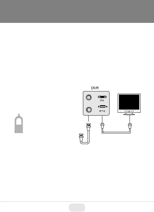
Power & Video Connections
Connect the HD-TVI Video or AHD/CVBS video connector to a BNC patch cable, then to a DVR. Next connect the power connector to a 12VDC or 24VAC power adaptor.
Monitor |
12VDC / 24VAC Power |
Video |
BNC Connections:
Green: HD Connection
Yellow: SD Connection
On Cable Switch:
Press & Hold button to cycle between HD-TVI, AHD, and CVI Modes (Green BNC Connection required).
Press & Release the Switch quickly to enter OSD Menu Screen.
3
 Loading...