


 Loading...
Altivar 71
Modbus Plus card
User's manual
VW3 A3 302 |
11/2010 |
1755869
www.schneider-electric.com

Contents
1.Before you begin___________________________________________________________________________________________ 3
2.Documentation structure_____________________________________________________________________________________ 4
3.Introduction_______________________________________________________________________________________________ 5
3.1. Presentation _________________________________________________________________________________________ 5
3.2. Notation ____________________________________________________________________________________________ 5
4.Hardware setup ___________________________________________________________________________________________ 6
4.1. Receipt _____________________________________________________________________________________________ 6
4.2. Hardware description __________________________________________________________________________________ 6
4.3. Installing the card in the drive____________________________________________________________________________ 6
4.4. Configuring the switches________________________________________________________________________________ 7
5.Connecting to the network ___________________________________________________________________________________ 8
5.1. Connector pinout _____________________________________________________________________________________ 8
5.2. Connection accessories ________________________________________________________________________________ 8
5.3. Modbus Plus wiring system _____________________________________________________________________________ 9
6.Modbus Plus menu________________________________________________________________________________________ 11
6.1. Access via graphic display terminal ______________________________________________________________________ 11
6.2. Access via the integrated display terminal _________________________________________________________________ 11
6.3. Modbus Plus parameters ______________________________________________________________________________ 12
7.Configuration ____________________________________________________________________________________________ 13
7.1. Communication parameters ____________________________________________________________________________ 13
7.2. Control - Signaling ___________________________________________________________________________________ 14
7.3. Communication scanner_______________________________________________________________________________ 17
7.4. Communication faults _________________________________________________________________________________ 19
7.5. Monitored parameters_________________________________________________________________________________ 20
8.Diagnostics ______________________________________________________________________________________________ 21
8.1. Checking the address_________________________________________________________________________________ 21
8.2. LEDs______________________________________________________________________________________________ 21
8.3. Control - Signaling ___________________________________________________________________________________ 22
8.4. Communication scanner_______________________________________________________________________________ 23
8.5. Communication fault __________________________________________________________________________________ 24
8. 6. Card fault _____________________________________________________________________________________________ 24
While every precaution has been taken in the preparation of this document, Schneider Electric SA assumes no liability for any omissions or errors it may contain, nor for any damages resulting from the application or use of the information herein.
The products and options described in this document may be changed or modified at any time, either from a technical point of view or in the way they are operated. Their description can in no way be considered contractual.
2 |
1755869 |
11/2010 |

1. Before you begin
Read and understand these instructions before performing any procedure with this drive.
 DANGER
HAZARDOUS VOLTAGE
•Read and understand the Installation Manual before installing or operating the Altivar 71 drive. Installation, adjustment, repair, and maintenance must be performed by qualified personnel.
•The user is responsible for compliance with all international and national electrical standards in force concerning protective grounding of all equipment.
•Many parts of this variable speed drive, including the printed circuit boards, operate at the line voltage. DO NOT TOUCH. Use only electrically insulated tools.
•DO NOT touch unshielded components or terminal strip screw connections with voltage present.
•DO NOT short across terminals PA and PC or across the DC bus capacitors.
•Install and close all the covers before applying power or starting and stopping the drive.
•Before servicing the variable speed drive
-Disconnect all power.
-Place a “DO NOT TURN ON” label on the variable speed drive disconnect.
-Lock the disconnect in the open position.
•Disconnect all power including external control power that may be present before servicing the drive. WAIT 15 MINUTES to allow the DC bus capacitors to discharge. Then follow the DC bus voltage measurement procedure given in the Installation Manual to verify that the DC voltage is less than 45 VDC. The drive LEDs are not accurate indicators of the absence of DC bus voltage.
Electric shock will result in death or serious injury.
CAUTION
DAMAGED EQUIPMENT
Do not install or operate any drive that appears damaged.
Failure to follow this instruction can result in equipment damage.
1755869 |
11/2010 |
3 |

2. Documentation structure
The following Altivar 71 technical documents are available on the Web site www.schneider-electric.com.
b Installation Manual
This manual describes:
•How to assemble the drive
•How to connect the drive
b Programming Manual
This manual describes:
•The functions
•The parameters
•How to use the drive display terminal (integrated display terminal and graphic display terminal)
b Communication Parameters Manual
This manual describes:
•The drive parameters with specific information (addresses, formats, etc.) for use via a bus or communication network
•The operating modes specific to communication (state chart)
•The interaction between communication and local control
b Modbus®, CANopen®, Ethernet™, Profibus®, INTERBUS, Uni-Telway, DeviceNet™, Modbus® Plus,
Fipio, etc., manuals
These manuals describe:
•Connection to the bus or network
•Configuration of the communication-specific parameters via the integrated display terminal or the graphic display terminal
•Diagnostics
•Software setup
•The communication services specific to the protocol
b Altivar 58/58F Migration Manual
This manual describes the differences between the Altivar 71 and the Altivar 58/58F.
It explains how to replace an Altivar 58 or 58F, including how to replace drives communicating on a bus or network.
4 |
1755869 |
11/2010 |

3. Introduction
3. 1. Presentation
The Modbus Plus communication card (catalog number VW3 A3 302) is used to connect an Altivar 71 drive to a Modbus Plus network.
The data exchanges permit full drive functionality:
•PeerCop control and adjustment
•Monitoring using the Global Data service
•Configuration, adjustment and diagnostics using the Modbus message handling service
If the Peer Cop service is not used for control, the drive can be controlled using the Modbus message handling service.
The card has a 9-way female SUB-D connector for connection to the Modbus Plus network.
The address of the drive is configured using the switches on the card.
The graphic display terminal on the drive can be used to access numerous functions for communication diagnostics.
The cable and accessories for connection to the Modbus Plus network must be ordered separately.
3. 2. Notation
Drive terminal displays
The graphic display terminal menus are shown in square brackets.
Example: [1.9 COMMUNICATION].
The integrated 7-segment display terminal menus are shown in round brackets.
Example: (COM-).
Parameter names are displayed on the graphic display terminal in square brackets.
Example: [Fallback speed]
Parameter codes are displayed on the integrated 7-segment display terminal in round brackets.
Example: (LFF).
Formats
In this manual:
-Hexadecimal values are written as follows: 16#
-Binary values are written as follows: 2#
1755869 |
11/2010 |
5 |
4. Hardware setup
4. 1. Receipt
Check that the card catalog number marked on the label is the same as that on the delivery note corresponding to the purchase order. Remove the option card from its packaging and check that it has not been damaged in transit.
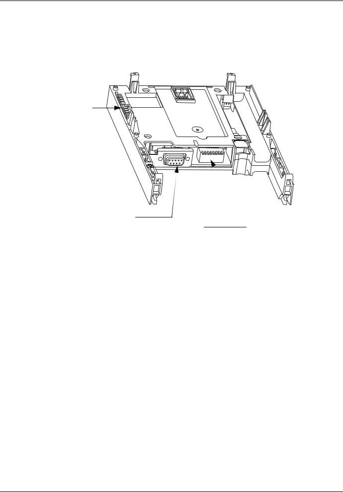
4. 2. Hardware description
Green LED
9-way female SUB-D connector
8 addressing switches, also used to select the mode (normal or ATV58/58F migration)
4. 3. Installing the card in the drive
See the Installation Manual.
6 |
1755869 |
11/2010 |

4. Hardware setup
4. 4. Configuring the switches
The switches are used to configure the mode (normal or Altivar 58/58F migration) and the address on the network.
The correspondence between the drive and the position of the switch is as follows:
•0 = OFF = Switch in upper position
•1 = ON = Switch in lower position
The switch on the right-hand side is used to configure the Modbus Plus card mode:
•0 = OFF = normal mode
•1 = ON = Altivar 58/58F migration mode This manual only describes normal mode.
To find out about Altivar 58 migration mode, refer to the Altivar 58/58F Migration Manual.
The table below indicates the positions of the switches for all configurable addresses (1 to 64) in normal mode:
Address |
Switches |
Address |
Switches |
Address |
Switches |
Address |
Switches |
1 |
0000 0000 |
17 |
0000 1000 |
33 |
0000 0100 |
49 |
0000 1100 |
2 |
1000 0000 |
18 |
1000 1000 |
34 |
1000 0100 |
50 |
1000 1100 |
3 |
0100 0000 |
19 |
0100 1000 |
35 |
0100 0100 |
51 |
0100 1100 |
4 |
1100 0000 |
20 |
1100 1000 |
36 |
1100 0100 |
52 |
1100 1100 |
5 |
0010 0000 |
21 |
0010 1000 |
37 |
0010 0100 |
53 |
0010 1100 |
6 |
1010 0000 |
22 |
1010 1000 |
38 |
1010 0100 |
54 |
1010 1100 |
7 |
0110 0000 |
23 |
0110 1000 |
39 |
0110 0100 |
55 |
0110 1100 |
8 |
1110 0000 |
24 |
1110 1000 |
40 |
1110 0100 |
56 |
1110 1100 |
9 |
0001 0000 |
25 |
0001 1000 |
41 |
0001 0100 |
57 |
0001 1100 |
10 |
1001 0000 |
26 |
1001 1000 |
42 |
1001 0100 |
58 |
1001 1100 |
11 |
0101 0000 |
27 |
0101 1000 |
43 |
0101 0100 |
59 |
0101 1100 |
12 |
1101 0000 |
28 |
1101 1000 |
44 |
1101 0100 |
60 |
1101 1100 |
13 |
0011 0000 |
29 |
0011 1000 |
45 |
0011 0100 |
61 |
0011 1100 |
14 |
1011 0000 |
30 |
1011 1000 |
46 |
1011 0100 |
62 |
1011 1100 |
15 |
0111 0000 |
31 |
0111 1000 |
47 |
0111 0100 |
63 |
0111 1100 |
16 |
1111 0000 |
32 |
1111 1000 |
48 |
1111 0100 |
64 |
1111 1100 |
Examples:
Address 10
Address 23
1755869 |
11/2010 |
7 |
5. Connecting to the network
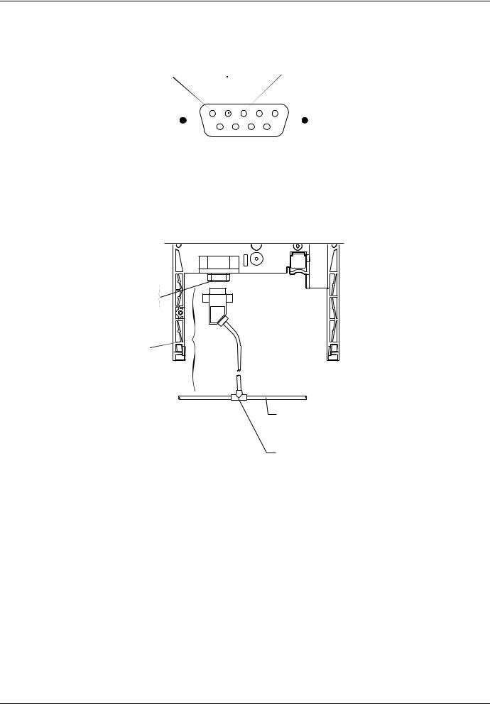
5. 1. Connector pinout
Contact 1 |
Contact 2 |
Contact 3 |
|
shield |
signal |
signal |
|
|
|
|
|
|
|
|
|
9-way female SUB-D connector
5. 2. Connection accessories
Modbus Plus card VW3 A3 302
9-way female SUB-D connector on card
Modbus Plus 990 NAD 219pp drop cable (2, 4 or 6 m)
Modbus Plus 490 NAA 271pp trunk cable
Modbus Plus tap 990 NAD 230 00
8 |
1755869 |
11/2010 |
Loading...