Motorola MC74LCX258D, MC74LCX258DT, MC74LCX258M, MC74LCX258SD Datasheet

MOTOROLA
SEMICONDUCTOR TECHNICAL DATA
Product |
Preview |
|
|
Low-Voltage CMOS Quad |
MC74LCX258 |
||
|
|
||
2-Input |
Multiplexer |
|
|
With 5V-Tolerant Inputs and Outputs |
|
|
|
(3-State, |
Inverting) |
|
|
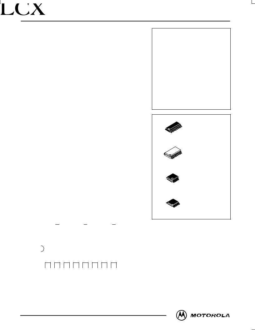
The MC74LCX258 is a high performance, quad 2±input inverting |
|
|
|
multiplexer with 3±state outputs operating from a 2.7 to 3.6V supply. High |
|
LOW±VOLTAGE CMOS |
|
impedance TTL compatible inputs significantly reduce current loading to |
|
||
input drivers while TTL compatible outputs offer improved switching noise |
QUAD 2±INPUT MULTIPLEXER |
||
performance. A VI specification of 5.5V allows MC74LCX258 inputs to be |
|
|
|
safely driven from 5V devices. |
|
|
|
Four bits of data from two sources can be selected using the Select |
|
|
|
input. The four outputs present the selected data in the inverted form. The |
|
|
|
outputs may be switched to a high impedance state by placing a logic |
|
D SUFFIX |
|
HIGH on the Output Enable (OE) input. Current drive capability is 24mA |
|
||
|
PLASTIC SOIC |
||
at the outputs. |
|
16 |
|
|
|
CASE 751B±05 |
|
|
|
|
|
|
|
|
1 |
• Designed for 2.7 to 3.6V VCC Operation |
|
|
|
• 5V Tolerant Ð Interface Capability With 5V TTL Logic |
|
M SUFFIX |
|
• Supports Live Insertion and Withdrawal |
|
||
16 |
PLASTIC SOIC EIAJ |
||
• IOFF Specification Guarantees High Impedance When VCC = 0V |
|
CASE 966±01 |
|
|
1 |
||
•LVTTL Compatible
•LVCMOS Compatible
• 24mA Balanced Output Sink and Source Capability |
16 |
|
SD SUFFIX |
• Near Zero Static Supply Current in All Three Logic States (10μA) |
|
PLASTIC SSOP |
|
|
1 |
CASE 940B±03 |
|
Substantially Reduces System Power Requirements |
|
|
|
|
|
|
|
• Latchup Performance Exceeds 500mA |
|
|
|
• ESD Performance: Human Body Model >2000V; Machine Model >200V |
|
|
DT SUFFIX |
|
|
|
|
|
16 |
|
PLASTIC TSSOP |
|
|
1 |
CASE 948F±01 |
|
|
|
|
Pinout: 16±Lead Plastic Package |
|
|
|
(Top View) |
|
|
|
VCC |
OE |
|
I0c |
|
I1c |
|
Zc |
|
I0d |
|
I1d |
|
Zd |
|||
|
16 |
|
15 |
|
14 |
|
13 |
|
12 |
|
11 |
|
10 |
|
9 |
|
|
|
|
|
|
|
|
|
|
|
|
|
|
|
|
|
|
|
|
|
|
|
|
|
|
|
|
|
|
|
|
|
|
|
|
|
|
|
|
|
|
|
|
|
|
|
|
|
|
|
|
1 |
|
2 |
|
3 |
|
4 |
|
5 |
|
6 |
|
7 |
|
8 |
S |
I0a |
|
I1a |
|
Za |
|
I0b |
|
I1b |
Zb |
GND |
|||
PIN NAMES
|
Pins |
Function |
|
|
|
|
|
|
I0n |
Source 0 Data Inputs |
|
|
I1n |
Source 1 Data Inputs |
|
|
OE |
Output Enable Input |
|
|
S |
|
Select Input |
|
Zn |
Outputs |
|
|
|
|
|
This document contains information on a product under development. Motorola reserves the right to change or discontinue this product without notice.
11/96
Motorola, Inc. 1996 |
1 |
REV 0 |

MC74LCX258
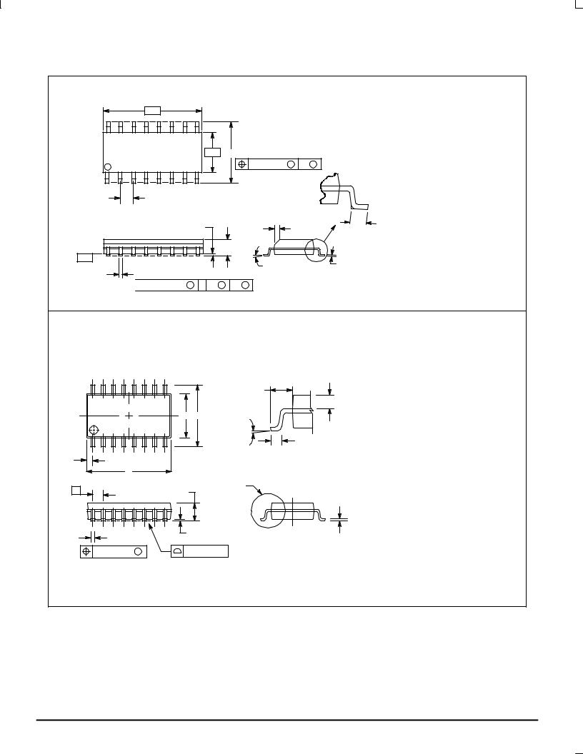
OUTLINE DIMENSIONS
|
D SUFFIX |
|
PLASTIC SOIC PACKAGE |
±A |
CASE 751B±05 |
± |
ISSUE J |
16 |
9 |
|
|
±B P 8 PL |
|
|
1 |
8 |
± |
0.25 (0.010) M |
B M |
|
||||
|
|
|
|
G |
|
|
|
K |
|
F |
|
|
R X 45° |
|
|
|
C |
|
±T |
|
|
J |
SEATING± |
|
M |
|
PLANE |
D 16 PL |
|
|
|
|
|


 0.25 (0.010) M T B S A S
NOTES:
1.DIMENSIONING AND TOLERANCING PER ANSI Y14.5M, 1982.
2.CONTROLLING DIMENSION: MILLIMETER.
3.DIMENSIONS A AND B DO NOT INCLUDE MOLD PROTRUSION.
4.MAXIMUM MOLD PROTRUSION 0.15 (0.006) PER SIDE.
5.DIMENSION D DOES NOT INCLUDE DAMBAR PROTRUSION. ALLOWABLE DAMBAR PROTRUSION SHALL BE 0.127 (0.005) TOTAL IN EXCESS OF THE D DIMENSION AT MAXIMUM MATERIAL CONDITION.
|
MILLIMETERS |
INCHES |
||
DIM |
MIN |
MAX |
MIN |
MAX |
A |
9.80 |
10.00 |
0.386 |
0.393 |
B |
3.80 |
4.00 |
0.150 |
0.157 |
C |
1.35 |
1.75 |
0.054 |
0.068 |
D |
0.35 |
0.49 |
0.014 |
0.019 |
F |
0.40 |
1.25 |
0.016 |
0.049 |
G |
1.27 |
BSC |
0.050 |
BSC |
J |
0.19 |
0.25 |
0.008 |
0.009 |
K |
0.10 |
0.25 |
0.004 |
0.009 |
M |
0° |
7° |
0° |
7° |
P |
5.80 |
6.20 |
0.229 |
0.244 |
R |
0.25 |
0.50 |
0.010 |
0.019 |
|
|
M SUFFIX |
|
|
PLASTIC SOIC EIAJ PACKAGE |
|
|
CASE 966±01 |
|
|
ISSUE O |
16 |
9 |
LE |
|
|
Q1 |
|
E HE |
M _ |
1 |
8 |
L |
|
||
|
Z |
DETAIL P |
|
|
|
|
D |
|
e |
VIEW P |
A |
|
|
c |
b |
A1 |
|
|
0.13 (0.005) M |
0.10 (0.004) |
NOTES:
1DIMENSIONING AND TOLERANCING PER ANSI Y14.5M, 1982.
2CONTROLLING DIMENSION: MILLIMETER.
3DIMENSIONS D AND E DO NOT INCLUDE MOLD FLASH OR PROTRUSIONS AND ARE MEASURED AT THE PARTING LINE. MOLD FLASH OR PROTRUSIONS SHALL NOT EXCEED 0.15 (0.006) PER SIDE.
4TERMINAL NUMBERS ARE SHOWN FOR REFERENCE ONLY.
5THE LEAD WIDTH DIMENSION (b) DOES NOT INCLUDE DAMBAR PROTRUSION. ALLOWABLE DAMBAR PROTRUSION SHALL BE 0.08 (0.003) TOTAL IN EXCESS OF THE LEAD WIDTH DIMENSION AT MAXIMUM MATERIAL CONDITION. DAMBAR CANNOT BE LOCATED ON THE LOWER RADIUS OR THE FOOT. MINIMUM SPACE BETWEEN PROTRUSIONS AND ADJACENT LEAD TO BE 0.46 ( 0.018).
|
MILLIMETERS |
INCHES |
||
DIM |
MIN |
MAX |
MIN |
MAX |
A |
--- |
2.05 |
--- |
0.081 |
A1 |
0.05 |
0.20 |
0.002 |
0.008 |
b |
0.35 |
0.50 |
0.014 |
0.020 |
c |
0.18 |
0.27 |
0.007 |
0.011 |
D |
9.90 |
10.50 |
0.390 |
0.413 |
E |
5.10 |
5.45 |
0.201 |
0.215 |
e |
1.27 BSC |
0.050 BSC |
||
HE |
7.40 |
8.20 |
0.291 |
0.323 |
L |
0.50 |
0.85 |
0.020 |
0.033 |
LE |
1.10 |
1.50 |
0.043 |
0.059 |
M |
0 _ |
10 _ |
0 _ |
10 _ |
Q1 |
0.70 |
0.90 |
0.028 |
0.035 |
Z |
--- |
0.78 |
--- |
0.031 |
MOTOROLA |
2 |
LCX DATA |
|
|
BR1339 Ð REV 3 |
 Loading...