


Features
Conforms to battery manufacturers' charge recommendations for cyclic and float charge
Pin-selectable charge algorithms
-Two-Step Voltage with temperature-compensated constant-voltage maintenance
-Two-Step Current with constant-rate pulsed current maintenance
-Pulsed Current: hysteretic, on-demand pulsed current
Pin-selectable charge termination by maximum voltage,∆2V, minimum current, and maximum time
Pre-charge qualification detects shorted, opened, or damaged cells and conditions battery
Charging continuously qualified by temperature and voltage limits
Internal temperature-compen- sated voltage reference
Pulse-width modulation control
bq2031
Lead-Acid Fast-Charge IC
-Ideal for high-efficiency switch-mode power conversion
-Configurable for linear or gated current use
Direct LED control outputs display charge status and fault conditions
General Description
The bq2031 Lead-Acid Fast Charge IC is designed to optimize charging of lead-acid chemistry batteries. A flexible pulse-width modulation regulator allows the bq2031 to control constant-voltage, constantcurrent, or pulsed-current charging. The regulator frequency is set by an external capacitor for design flexibility. The switch-mode design keeps power dissipation to a minimum for high charge current applications.
A charge cycle begins when power is applied or the battery is replaced. For safety, charging is inhibited until the battery voltage is within configured limits. If the battery voltage is less than the low-voltage threshold, the bq2031 provides trickle-current
charging until the voltage rises into the allowed range or an internal timer runs out and places the bq2031 in a Fault condition. This procedure prevents high-current charging of cells that are possibly damaged or reversed. Charging is inhibited anytime the temperature of the battery is outside the configurable, allowed range. All voltage thresholds are temperaturecompensated.
The bq2031 terminates fast (bulk) charging based on the following:
■Maximum voltage
■Second difference of cell voltage (∆2V)
■Minimum current (in constantvoltage charging)
■Maximum time-out (MTO)
After bulk charging, the bq2031 provides temperature-compensated maintenance (float) charging to maintain battery capacity.
Pin Connections |
Pin Names |
TMTO |
1 |
16 |
LED2/DSEL |
FLOAT |
2 |
15 |
LED1/TSEL |
BAT |
3 |
14 |
MOD |
VCOMP |
4 |
13 |
VCC |
ICOMP |
5 |
12 |
VSS |
IGSEL |
6 |
11 |
COM |
SNS |
7 |
10 |
LED3/QSEL |
TS |
8 |
9 |
TPWM |
|
|
|
|
16-Pin Narrow
DIP or SOIC
PN203101.eps
TMTO |
Time-out timebase input |
LED3/ |
Charge status output 3/ |
|
|
QSEL |
Charge algorithm select |
FLOAT |
State control output |
|
input 1 |
BAT |
Battery voltage input |
COM |
Common LED output |
VCOMP |
Voltage loop comp input |
VSS |
System ground |
ICOMP |
Current loop comp input |
VCC |
5.0V±10% power |
IGSEL |
Current gain select input |
MOD |
Modulation control |
|
|
|
output |
SNS |
Sense resistor input |
LED1/ |
Charge status output 1/ |
|
|
||
TS |
Temperature sense input |
TSEL |
Charge algorithm select |
|
|
|
input 2 |
TPWM |
Regulator timebase input |
LED2/ |
Charge status output 2/ |
|
|
||
|
|
DSEL |
Display select input |
SLUS156–JUNE 1999 E
1

bq2031
Pin Descriptions
TMTO |
Time-out timebase input |
|
This input sets the maximum charge time. |
|
The resistor and capacitor values are deter- |
|
mined using equation 6. Figure 9 shows the |
|
resistor/capacitor connection. |
FLOAT |
Float state control output |
|
This open-drain output uses an external re- |
|
sistor divider network to control the BAT in- |
|
put voltage threshold (VFLT) for the float |
|
charge regulation. See Figure 1. |
BAT |
Battery voltage input |
|
BAT is the battery voltage sense input. This po- |
|
tential is generally developed using a high- |
|
impedance resistor divider network connected |
|
between the positive and the negative terminals |
|
of the battery. See Figure 6 and equation 2. |
VCOMP |
Voltage loop compensation input |
|
This input uses an external C or R-C net- |
|
work for voltage loop stability. |
IGSEL |
Current gain select input |
|
This three-state input is used to set IMIN for |
|
fast charge termination in the Two-Step |
|
Voltage algorithm and for maintenance cur- |
|
rent regulation in the Two-Step Current al- |
|
gorithm. See Tables 3 and 4. |
ICOMP |
Current loop compensation input |
|
This input uses an external C or R-C net- |
|
work for current loop stability. |
SNS |
Charging current sense input |
|
Battery current is sensed via the voltage de- |
|
veloped on this pin by an external sense re- |
|
sistor, RSNS, connected in series with the low |
|
side of the battery. See equation 8. |
TS |
Temperature sense input |
|
This input is for an external battery tem- |
|
perature monitoring thermistor or probe. An |
|
external resistor divider network sets the |
|
lower and upper temperature thresholds. |
|
See Figures 7 and 8 and equations 4 and 5. |
TPWM |
Regulation timebase input |
|
This input uses an external timing capacitor |
|
to ground the pulse-width modulation |
|
(PWM) frequency. See equation 9. |
COM |
Common LED output |
|
Common output for LED1–3. This output is |
|
in a high-impedance state during initiali- |
|
zation to read program inputs on TSEL, |
|
QSEL, and DSEL. |
QSEL |
Charge regulation select input |
|
With TSEL, selects the charge algorithm. |
|
See Table 1. |
MOD |
Current-switching control output |
|
MOD is a pulse-width modulated push/pull |
|
output that is used to control the charging |
|
current to the battery. MOD switches high |
|
to enable current flow and low to inhibit cur- |
|
rent flow. |
LED1–3 |
Charger display status 1–3 outputs |
|
These charger status output drivers are for |
|
the direct drive of the LED display. Display |
|
modes are shown in Table 2. These outputs are |
|
tri-stated during initialization so that QSEL, |
|
TSEL, and DSEL can be read. |
DSEL |
Display select input |
|
This three-level input controls the LED1–3 |
|
charge display modes. See Table 2. |
TSEL |
Termination select input |
|
With QSEL, selects the charge algorithm. |
|
See Table 1. |
VCC |
VCC supply |
|
5.0V, ± 10% power |
VSS |
Ground |
Functional Description
The bq2031 functional operation is described in terms of:
Charge algorithms
Charge qualification
Charge status display
Voltage and current monitoring
Temperature monitoring
2
|
|
|
|
|
bq2031 |
|
Fast charge termination |
|
|
|
|
|
Maintenance charging |
|
|
|
|
|
Charge regulation |
|
Chip On |
|
|
|
VCC 4.5V |
|
|
||
|
|
|
Temperature Out |
|
|
|
|
|
|
of Range or |
|
Charge Algorithms |
|
Thermistor Absent |
|
||
|
Checks On |
|
|
||
|
|
|
Temperature |
|
|
Three charge algorithms are available in the bq2031: |
Temperature |
Absent |
|
||
Present |
in Range |
|
|||
|
|
VLCO < VCELL < VHCO |
VCELL < VLCO or |
|
|
|
|
Battery |
VCELL > VHCO |
|
|
|
Two-Step Voltage |
Test 1 |
|
||
Status? |
|
|
|||
|
Two-Step Current |
ISNS < ICOND |
Fail: |
|
|
Voltage |
VCELL > VHCO |
|
|
||
|
|
|
t = tQT1 or |
|
|
|
|
Regulation |
|
Fault |
|
|
|
LED3 = 1 |
|
||
|
Pulsed Current |
@ VFLT + |
|
||
|
MOD = 0 |
|
|||
0.25V |
|
VCELL |
VLCO or |
||
|
|
PASS: ISNS > ICOND |
|
VCELL |
VHCO |
The state transitions for these algorithms are described |
|
|
|
||
Test 2 |
|
|
|
||
in Table 1 and are shown graphically in Figures 2 |
Fail: |
|
|
||
VCELL < VMIN |
t = tQT2 or |
Charge |
|
||
through 4. The user selects a charge algorithm by con- |
Current |
VCELL > VHCO |
|
||
|
|
|
VCELL < VLCO or |
|
|
figuring pins QSEL and TSEL. |
Regulation |
|
LED3 Flash |
||
@ICOND |
|
||||
|
|
|
|
Pending |
|
|
|
|
|
MOD = 0 |
Temperature Out |
|
|
|
|
|
|
Charge Qualification |
PASS: VCELL > VMIN |
VCELL < VLCO or |
|
of Range or |
|
|
|
Thermistor Absent |
|||
|
|
Bulk |
VCELL > VHCO |
Fast |
Temperature In |
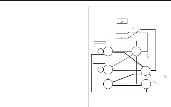
The bq2031 starts a charge cycle when power is applied |
|
Range, Return |
|||
Charge |
|
Charge |
to Original State |
||
|
Termination |
|
|
||
while a battery is present or when a battery is inserted. |
|
VCELL < VMIN |
|
||
Figure 1 shows the state diagram for pre-charge qualifi- |
|
|
|
|
|
cation and temperature monitoring. The bq2031 first |
|
|
FG203101.eps |
||
|
|
|
|
||
checks that the battery temperature is within the al- |
|
|
|
|
|
lowed, user-configurable range. If the temperature is |
|
|
|
|
|
out-of-range (or the thermistor is missing), the bq2031 |
|
|
|
|
|
enters the Charge Pending state and waits until the bat- |
|
|
|
|
|
tery temperature is within the allowed range. Charge |
Figure 1. Cycle Start/Battery |
||||
Pending is annunciated by LED3 flashing. |
Qualification State Diagram |
||||
|
|
||||
Table 1. bq2031 Charging Algorithms
Algorithm/State |
QSEL |
TSEL |
|
Conditions |
MOD Output |
|
Two-Step Voltage |
L |
H/LNote 1 |
|
- |
- |
|
Fast charge, phase 1 |
|
|
|
while VBAT < VBLK, ISNS = IMAX |
Current regulation |
|
Fast charge, phase 2 |
|
|
|
while ISNS > IMIN, VBAT = VBLK |
Voltage regulation |
|
Primary termination |
|
|
|
ISNS = IMIN |
|
|
Maintenance |
|
|
|
VBAT = VFLT |
Voltage regulation |
|
|
|
|
|
|
|
|
Two-Step Current |
H |
L |
|
- |
- |
|
Fast charge |
|
|
|
while VBAT < VBLK, ISNS = IMAX |
Current regulation |
|
Primary termination |
|
|
|
VBAT = VBLK or ∆2V < -8mVNote 2 |
|
|
Maintenance |
|
|
|
ISNS pulsed to average IFLT |
Fixed pulse current |
|
|
|
|
|
|
|
|
Pulsed Current |
H |
H |
|
- |
- |
|
Fast charge |
|
|
|
while VBAT < VBLK, ISNS = IMAX |
Current regulation |
|
Primary termination |
|
|
|
VBAT = VBLK |
|
|
Maintenance |
|
|
|
ISNS = IMAX after VBAT = VFLT; |
Hysteretic pulsed |
|
|
|
|
ISNS = 0 after VBAT = VBLK |
current |
||
|
|
|
|
|
||
Notes: |
1. May be high or low, but do not float. |
|
|
|||
|
2. A Unitrode proprietary algorithm for accumulating successive differences between samples of VBAT. |
|||||
3

bq2031
Thermal monitoring continues throughout the charge cycle, and the bq2031 enters the Charge Pending state anytime the temperature is out of range. (There is one exception; if the bq2031 is in the Fault state—see be- low—the out-of-range temperature is not recognized until the bq2031 leaves the Fault state.) All timers are suspended (but not reset) while the bq2031 is in Charge Pending. When the temperature comes back into range, the bq2031 returns to the point in the charge cycle where the out-of-range temperature was detected.
When the temperature is valid, the bq2031 performs two tests on the battery. In test 1, the bq2031 regulates a voltage of VFLT + 0.25V across the battery and observes ISNS. If ISNS does not rise to at least ICOND within a time-out period (e.g., the cell has failed open), the bq2031 enters the Fault state. If test 1 passes, the bq2031 then regulates current to ICOND (= IMAX/5) and watches VCELL (= VBAT - VSNS). If VCELL does not rise to at least VFLT within a time-out period (e.g., the cell has failed short), again the bq2031 enters the Fault state. A hold-off period is enforced at the beginning of qualification
test 2 before the bq2031 recognizes its “pass” criterion. If this second test passes, the bq2031 begins fast (bulk) charging.
Once in the Fault state, the bq2031 waits until VCC is cycled or a battery insertion is detected. It then starts a new charge cycle and begins the qualification process again.
Charge Status Display
Charge status is annunciated by the LED driver outputs LED1–LED3. Three display modes are available in the bq2031; the user selects a display mode by configuring pin DSEL. Table 2 shows the three modes and their programming pins.
The bq2031 does not distinguish between an over-voltage fault and a “battery absent” condition. The bq2031 enters the Fault state, annunciated by turning on LED3, whenever the battery is absent. The bq2031, therefore, gives an indication that the charger is on even when no battery is in place to be charged.
Table 2. bq2031 Display Output Summary
Mode |
|
Charge Action State |
|
LED1 |
|
LED2 |
LED3 |
|
|
Battery absent or over-voltage fault |
|
Low |
|
Low |
High |
|
|
Pre-charge qualification |
|
Flash |
|
Low |
Low |
DSEL = 0 |
Fast charging |
|
High |
|
Low |
Low |
|
(Mode 1) |
Maintenance charging |
|
Low |
|
High |
Low |
|
|
|
Charge pending (temperature out of range) |
|
X |
|
X |
Flash |
|
|
Charging fault |
|
X |
|
X |
High |
|
|
|
|
|
|
|
|
|
|
Battery absent or over-voltage fault |
|
Low |
|
Low |
High |
|
|
Pre-charge qualification |
|
High |
|
High |
Low |
DSEL = 1 |
Fast charge |
|
Low |
|
High |
Low |
|
(Mode 2) |
Maintenance charging |
|
High |
|
Low |
Low |
|
|
|
Charge pending (temperature out of range) |
|
X |
|
X |
Flash |
|
|
Charging fault |
|
X |
|
X |
High |
|
|
|
|
|
|
|
|
|
|
Battery absent or over-voltage fault |
|
Low |
|
Low |
High |
|
|
Pre-charge qualification |
|
Flash |
|
Flash |
Low |
DSEL = Float |
Fast charge: current regulation |
|
Low |
|
High |
Low |
|
Fast charge: voltage regulation |
|
High |
|
High |
Low |
||
(Mode 3) |
|
|
|||||
Maintenance charging |
|
High |
|
Low |
Low |
||
|
|
|
|
||||
|
|
Charge pending (temperature out of range) |
|
X |
|
X |
Flash |
|
|
Charging fault |
|
X |
|
X |
High |
|
|
|
|
|
|
|
|
Notes: |
1 = VCC; 0 = VSS; X = LED state when fault occurred; Flash = 1 |
6 s low, 1 |
6 s high. |
|
|||
In the Pulsed Current algorithm, the bq2031 annunciates maintenance when charging current is off and fast charge whenever charging current is on.
4

bq2031
IMAX
Current
ICOND
IMIN
IFLT
Qualification
VBLK
|
Voltage |
VFLT |
|
|
|
||
|
Fast Charge |
Maintenance |
|
|
|
||
Phase 1 |
Phase 2 |
VMIN |
|
Voltage |
|||
|
Current |
||
|
|
Time
Figure 2. Two-Step Voltage Algorithm
IMAX
Current
ICOND
Qualification
Current
Voltage
Maintenance
Fast Charge
Time
Figure 3. Two-Step Current Algorithm
VBLK
VFLT
VMIN
Voltage
IMAX
Current
ICOND
Qualification
Maintenance
Current
Voltage
Fast Charge
Time
Figure 4. Pulsed Current Algorithm
VBLK
VFLT
VMIN
Voltage
5
 Loading...