


840D
Table of contents
 Loading...
SINUMERIK 840D sl/840D/840Di sl Cycles
_
_____________
_
_____________
_
_____________
_
_____________
_
_____________
_
_____________
_
_____________
_
_____________
Preface
General
1
Drilling cycles and
drilling patterns
2
Milling cycles
3
Turning cycles
4
Error messages and
Error handling
5
List of abbreviations
A
References
B
List of parameters
C
SINUMERIK 840D sl/840D/840Di sl
Cycles
Programming Manual
01/2008
6FC5398-3BP20-1BA0
Valid for
Controls
SINUMERIK 840D sl/840DE sl
SINUMERIK 840D powerline/840DE powerline
SINUMERIK 840Di sl/840DiE sl
Software Version
NCU system software for 840D sl/840DE sl 1.5
HMI Advanced 7.5
each with cycles 7.5

Safety Guidelines
This manual contains notices you have to observe in order to ensure your personal safety, as well as to prevent
damage to property. The notices referring to your personal safety are highlighted in the manual by a safety alert
symbol, notices referring only to property damage have no safety alert symbol. These notices shown below are
graded according to the degree of danger.
DANGER
indicates that death or severe personal injury will result if proper precautions are not taken.
WARNING
indicates that death or severe personal injury may result if proper precautions are not taken.
CAUTION
with a safety alert symbol, indicates that minor personal injury can result if proper precautions are not taken.
CAUTION
without a safety alert symbol, indicates that property damage can result if proper precautions are not taken.
NOTICE
indicates that an unintended result or situation can occur if the corresponding information is not taken into
account.
If more than one degree of danger is present, the warning notice representing the highest degree of danger will
be used. A notice warning of injury to persons with a safety alert symbol may also include a warning relating to
property damage.
Qualified Personnel
The device/system may only be set up and used in conjunction with this documentation. Commissioning and
operation of a device/system may only be performed by qualified personnel. Within the context of the safety notes
in this documentation qualified persons are defined as persons who are authorized to commission, ground and
label devices, systems and circuits in accordance with established safety practices and standards.
Prescribed Usage
Note the following:
WARNING
This device may only be used for the applications described in the catalog or the technical description and only
in connection with devices or components from other manufacturers which have been approved or
recommended by Siemens. Correct, reliable operation of the product requires proper transport, storage,
positioning and assembly as well as careful operation and maintenance.
Trademarks
All names identified by ® are registered trademarks of the Siemens AG. The remaining trademarks in this
publication may be trademarks whose use by third parties for their own purposes could violate the rights of the
owner.
Disclaimer of Liability
We have reviewed the contents of this publication to ensure consistency with the hardware and software
described. Since variance cannot be precluded entirely, we cannot guarantee full consistency. However, the
information in this publication is reviewed regularly and any necessary corrections are included in subsequent
editions.
Siemens AG
Automation and Drives
Postfach 48 48
90327 NÜRNBERG
GERMANY
Ordernumber: 6FC5398-3BP20-1BA0
Ⓟ 11/2007
Copyright © Siemens AG 2008.
Technical data subject to change

Cycles
Programming Manual, 01/2008, 6FC5398-3BP20-1BA0
3
Safety Guidelines
Preface
Preface
Structure of the documentation
The SINUMERIK documentation is organized in 3 parts:
● General documentation
● User documentation
● Manufacturer/service documentation
You can find a publications overview that is updated monthly indicating the currently
available languages on the Internet at:
http://www.siemens.com/motioncontrol
Follow the menu items "Support" → "Technical Documentation" → "Publications Overview".
The Internet version of the DOConCD, the DOConWEB, is available at:
http://www.automation.siemens.com/doconweb
Information about training courses and FAQs (Frequently Asked Questions) can be found at
the following website:
http://www.siemens.com/motioncontrol, under "Support"
Target group
This documentation is intended for machine tool programmers.
Benefits
This Programming manual enables the target group to develop, write, and test programs and
to correct errors.
Standard scope
The functionality of the standard scope (cycles SW 7.3) is described in this Programming
manual. Additions or changes made by the machine tool manufacturer are documented by
the machine tool manufacturer.
It may be possible to execute other functions not described in this documentation in the
control. This does not, however, represent an obligation to supply such functions with a new
control or when servicing.

Preface
Cycles
4 Programming Manual, 01/2008, 6FC5398-3BP20-1BA0
Further, for the sake of simplicity, this documentation does not contain all detailed
information about all types of the product and cannot cover every conceivable case of
installation, operation or maintenance.
Technical Support
If you have questions, contact the following hotline:
Europe and Africa time zone
A&D Technical Support
Tel.: +49 (0) 180 / 5050 - 222
Fax: +49 (0) 180 / 5050 - 223
Internet:
http://www.siemens.com/automation/support-request
E-mail: mailto:adsupport@siemens.com
Asia and Australia time zone
A&D Technical Support
Tel.: +86 1064 719 990
Fax: +86 1064 747 474
Internet:
http://www.siemens.com/automation/support-request
E-mail: mailto:adsupport@siemens.com
America time zone
A&D Technical Support
Tel.: +1 423 262 2522
Fax: +1 423 262 2289
Internet:
http://www.siemens.com/automation/support-request
E-mail: mailto:adsupport@siemens.com
Note
Country telephone numbers for technical support are provided at the following Internet
address:
http://www.siemens.com/automation/service&support
Questions about the Manual
If you have any queries (suggestions, corrections) in relation to this documentation, please
fax or e-mail us:
Fax: +49 (0) 9131 / 98 - 63315
E-mail: mailto:motioncontrol.docu@siemens.com

Preface
Cycles
Programming Manual, 01/2008, 6FC5398-3BP20-1BA0
5
Fax form: See the reply form at the end of this publication
SINUMERIK Internet address
http://www.siemens.com/sinumerik
Validity
This Programming Guide is valid for Cycles Version 7.3.
Structure of descriptions
All cycles and programming options have been described according to the same internal
structure, as far as this is meaningful and practicable. The various levels of information have
been organized such that you can selectively access the information you need for the task in
hand.
Supplementary devices
The applications of SIEMENS controls can be expanded for specific purposes through the
addition of special add-on devices, equipment and expansions supplied by SIEMENS.

Preface
Cycles
6 Programming Manual, 01/2008, 6FC5398-3BP20-1BA0

Cycles
Programming Manual, 01/2008, 6FC5398-3BP20-1BA0
7
Table of contents
Preface ...................................................................................................................................................... 3
1 General....................................................................................................................................................
11
1.1 Overview of cycles .......................................................................................................................
11
1.1.1 Drilling cycles, hole pattern cycles, milling cycles, and turning cycles ........................................
11
1.1.2 Cycle auxiliary subroutines ..........................................................................................................
13
1.2 Programming cycles ....................................................................................................................
14
1.2.1 Call and return conditions ............................................................................................................
14
1.2.2 Messages during execution of a cycle.........................................................................................
15
1.2.3 Cycle call and parameter list........................................................................................................
15
1.2.4 Simulation of cycles .....................................................................................................................
19
1.3 Cycle support in the program editor.............................................................................................
20
1.3.1 Menus, cycle selection.................................................................................................................
20
1.3.2 Functions of the input screen forms.............................................................................................
21
1.4 Cycle support for user cycles.......................................................................................................
30
1.4.1 Overview of necessary files .........................................................................................................
30
1.4.2 Getting started with cycle support................................................................................................
30
1.4.3 Cycle support configuration .........................................................................................................
31
1.4.4 Bitmap size and screen resolution...............................................................................................
32
1.4.5 Bitmap storage in the data management of HMI Advanced ........................................................
32
1.4.6 Bitmap handling for HMI Embedded............................................................................................
33
1.5 Cycle startup ................................................................................................................................
34
1.5.1 Machine data................................................................................................................................
34
1.5.2 Definition files for cycles GUD7.DEF and SMAC.DEF ................................................................
35
1.5.3 New delivery forms for cycles in HMI Advanced..........................................................................
36
1.5.4 Upgrading the cycles with SW 6.4 and higher in HMI Advanced with SW 6.3 and higher..........
37
1.6 Additional functions for cycles......................................................................................................
38
2 Drilling cycles and drilling patterns...........................................................................................................
41
2.1 Drilling cycles ...............................................................................................................................
41
2.1.1 General information .....................................................................................................................
41
2.1.2 Requirements...............................................................................................................................
42
2.1.3 Drilling, centering - CYCLE81......................................................................................................
44
2.1.4 Drilling, counterboring - CYCLE82:..............................................................................................
47
2.1.5 Deep-hole drilling - CYCLE83......................................................................................................
50
2.1.6 Rigid tapping - CYCLE84.............................................................................................................
58
2.1.7 Tapping with compensating chuck - CYCLE840 .........................................................................
65
2.1.8 Boring 1 - CYCLE85 ....................................................................................................................
72
2.1.9 Boring 2 - CYCLE86 ....................................................................................................................
75
2.1.10 Boring 3 - CYCLE87 ....................................................................................................................
79
2.1.11 Boring 4 - CYCLE88 ....................................................................................................................
82
2.1.12 Boring 5 - CYCLE89 ....................................................................................................................
85
2.2 Modal call of drilling cycles ..........................................................................................................
88

Table of contents
Cycles
8 Programming Manual, 01/2008, 6FC5398-3BP20-1BA0
2.3 Drilling pattern cycles .................................................................................................................. 91
2.3.1 Requirements..............................................................................................................................
91
2.3.2 Row of holes - HOLES1..............................................................................................................
92
2.3.3 Row of holes - HOLES2..............................................................................................................
95
2.3.4 Dot matrix - CYCLE801...............................................................................................................
98
3 Milling cycles .........................................................................................................................................
101
3.1 General information...................................................................................................................
101
3.2 Requirements............................................................................................................................
101
3.3 Thread milling - CYCLE90 ........................................................................................................
104
3.4 Long holes located on a circle - LONGHOLE ...........................................................................
111
3.5 Slots on a circle - SLOT1 ..........................................................................................................
117
3.6 Circumferential slot - SLOT2.....................................................................................................
125
3.7 Milling rectangular pockets - POCKET1 ...................................................................................
132
3.8 Milling circular pockets - POCKET2..........................................................................................
137
3.9 Milling a rectangular pocket - POCKET3 ..................................................................................
142
3.10 Milling a circular pocket - POCKET4.........................................................................................
150
3.11 Face milling - CYCLE71............................................................................................................
156
3.12 Path milling - CYCLE72 ............................................................................................................
163
3.13 Rectangular spigot milling - CYCLE76......................................................................................
173
3.14 Circular spigot milling - CYCLE77.............................................................................................
179
3.15 Pocket milling with islands - CYCLE73, CYCLE74, CYCLE75.................................................
184
3.15.1 General information...................................................................................................................
184
3.15.2 Transfer pocket edge contour - CYCLE74................................................................................
185
3.15.3 Transfer island contour - CYCLE75 ..........................................................................................
186
3.15.4 Pocket milling with islands - CYCLE73 .....................................................................................
189
3.15.4.1 General information...................................................................................................................
189
3.15.4.2 Examples...................................................................................................................................
192
3.15.4.3 Description of technology in Example 2....................................................................................
202
3.16 Swiveling – CYCLE800 .............................................................................................................
211
3.16.1 General information...................................................................................................................
211
3.16.2 Programming via screen form...................................................................................................
213
3.16.2.1 General information...................................................................................................................
213
3.16.2.2 Parameters of input screen form...............................................................................................
213
3.16.2.3 Operator and programmer instructions .....................................................................................
220
3.16.2.4 Examples of input screen form .................................................................................................
222
3.16.3 Programming using parameters................................................................................................
225
3.16.4 Setting of tools - CYCLE800 .....................................................................................................
228
3.16.5 Alignment of tools - CYCLE800 ................................................................................................
230
3.16.6 Setting up workpieces with swiveled machining planes ...........................................................
233
3.16.6.1 General information...................................................................................................................
233
3.16.6.2 Parameters of input screen form...............................................................................................
234
3.16.6.3 Data transfer of swivel data in “Swiveling in JOG"....................................................................
238
3.16.7 Startup - CYCLE800 .................................................................................................................
239
3.16.7.1 General information...................................................................................................................
239
3.16.7.2 Startup of kinematic chain.........................................................................................................
244
3.16.7.3 Starting up kinematic rotary axes..............................................................................................
252

Table of contents
Cycles
Programming Manual, 01/2008, 6FC5398-3BP20-1BA0
9
3.16.7.4 Startup of fine kinematics...........................................................................................................254
3.16.7.5 Startup examples for machine kinematics .................................................................................
255
3.16.8 Manufacturer Cycle TOOLCARR.SPF - CYCLE800 .................................................................
265
3.17 High speed settings - CYCLE832 ..............................................................................................
270
3.17.1 General information ...................................................................................................................
270
3.17.2 Programming via input screen form...........................................................................................
273
3.17.2.1 General information ...................................................................................................................
273
3.17.2.2 Parameters of input screen form................................................................................................
273
3.17.3 Programming via parameters.....................................................................................................
277
3.17.4 Customizing technology.............................................................................................................
278
3.17.4.1 General information ...................................................................................................................
278
3.17.4.2 Customizing of machine setter/programmer..............................................................................
278
3.17.4.3 Customization by the machine manufacturer ............................................................................
279
3.17.4.4 Customizing additional program parameters CYC_832T ..........................................................
280
3.17.5 Ports...........................................................................................................................................
283
3.18 Engraving cycle CYCLE60.........................................................................................................
285
3.19 Trochoidal milling / plunge cutting - CYCLE899 ........................................................................
298
3.19.1 General information ...................................................................................................................
298
3.19.2 Function .....................................................................................................................................
298
3.19.2.1 Vortex milling..............................................................................................................................
298
3.19.2.2 Plunge cutting ............................................................................................................................
300
3.19.3 Programming via a screen form.................................................................................................
302
3.19.3.1 General information ...................................................................................................................
302
3.19.3.2 Parameters of the screen form ..................................................................................................
303
3.19.4 Programming using parameters.................................................................................................
305
3.19.5 Programming example...............................................................................................................
309
4 Turning cycles .......................................................................................................................................
313
4.1 General information ...................................................................................................................
313
4.2 Conditions ..................................................................................................................................
313
4.3 Grooving cycle - CYCLE93 ........................................................................................................
317
4.4 Undercut cycle - CYCLE94 ........................................................................................................
328
4.5 Stock removal cycle - CYCLE95................................................................................................
333
4.6 Thread undercut - CYCLE96 .....................................................................................................
347
4.7 Thread cutting - CYCLE97.........................................................................................................
351
4.8 Thread chaining - CYCLE98......................................................................................................
359
4.9 Thread recutting.........................................................................................................................
366
4.10 Extended stock removal cycle - CYCLE950..............................................................................
367
5 Error messages and Error handling .......................................................................................................
387
5.1 General information ...................................................................................................................
387
5.2 Error handling in the cycles........................................................................................................
387
5.3 Messages in the cycles..............................................................................................................
388
A List of abbreviations...............................................................................................................................
389
B References ............................................................................................................................................
395
C List of parameters..................................................................................................................................
397

Table of contents
Cycles
10 Programming Manual, 01/2008, 6FC5398-3BP20-1BA0
Glossary ................................................................................................................................................ 401
Index......................................................................................................................................................
425

Cycles
Programming Manual, 01/2008, 6FC5398-3BP20-1BA0
11
General
1
The first section provides you with an overview of the available cycles. The following
sections describe the general conditions that apply to all cycles regarding
● Programming the cycles and
● Operator guidance for calling the cycles.
1.1 Overview of cycles
Cycles are generally applicable technology subroutines, with which you can implement
specific machining processes such as tapping a thread or milling a pocket. These cycles are
adapted to individual tasks by parameter assignment.
The system provides you with the technologies
● Drilling
● Milling
● Turning
in various standard cycles.
1.1.1 Drilling cycles, hole pattern cycles, milling cycles, and turning cycles
You can run the following cycles with the SINUMERIK 810D, 840D and 840Di controls:
Drilling cycles
CYCLE81
Drilling, centering
CYCLE82
Drilling, counterboring
CYCLE83
Deep-hole drilling
CYCLE84
Rigid tapping
CYCLE840
Tapping with compensating chuck
CYCLE85
Boring 1
CYCLE86
Boring 2
CYCLE87
Boring 3
CYCLE88
Boring 4
CYCLE89
Boring 5

General
1.1 Overview of cycles
Cycles
12 Programming Manual, 01/2008, 6FC5398-3BP20-1BA0
Hole pattern cycles
HOLES1
Machining a row of holes
HOLES2
Machining a circle of holes
CYCLE801
Dot matrix
Milling cycles
CYCLE90
Thread milling
LONGHOLE
Milling pattern of elongated holes on a circle
SLOT1
Groove milling pattern on a circle
SLOT2
Circumferential groove milling pattern
POCKET1
Rectangular pocket milling (with face cutter)
POCKET2
Circular pocket milling (with face cutter)
POCKET3
Rectangular pocket milling (with any milling tool)
POCKET4
Circular pocket milling (with any milling tool)
CYCLE71
Face milling
CYCLE72
Contour milling
CYCLE76
Rectangular spigot milling
CYCLE77
Circular spigot milling
CYCLE73
Pocket milling with islands
CYCLE74
Transfer of pocket edge contour
CYCLE75
Transfer of island contour
CYCLE800
Swiveling
CYCLE832
High speed settings
CYCLE60
Engraving cycle
CYCLE899
Trochoidal milling / plunge cutting
Turning cycles
CYCLE93
Recess
CYCLE94
Undercut (DIN form E and F)
CYCLE95
Stock removal with relief cutting
CYCLE96
Thread undercut (DIN forms A, B, C, and D)
CYCLE97
Thread cutting
CYCLE98
Chaining of threads
CYCLE950
Extended stock removal

General
1.1 Overview of cycles
Cycles
Programming Manual, 01/2008, 6FC5398-3BP20-1BA0
13
1.1.2 Cycle auxiliary subroutines
Included in the cycle package is the auxiliary subroutine
● PITCH
This auxiliary subroutine must always be loaded in the control.

General
1.2 Programming cycles
Cycles
14 Programming Manual, 01/2008, 6FC5398-3BP20-1BA0
1.2 Programming cycles
A standard cycle is defined as a subroutine with name and parameter list. The conditions
described in the "SINUMERIK Programming Guide Part 1: Fundamentals" are applicable for
calling a cycle.
Note
The cycles are supplied on diskette/CD or with the relevant software version for HMI
Advanced. They are loaded to the part program memory of the control via the V.24 interface
or from the diskette drive (see operator's guide).
1.2.1 Call and return conditions
The G functions active before the cycle is called and the programmable frame remain active
beyond the cycle.
You define the machining plane (G17, G18, G19) before the cycle call. A cycle operates in
the current plane with the
● Abscissa (1st geometry axis)
● Ordinate (2nd geometry axis)
● Applicate (3rd geometry axis of the plane in space)
In the drilling cycles, the drilling is executed in the axis that is vertical on the plane (3rd
geometry plane). In milling, the depth infeed is carried out in this axis.
*
*
*
$SSOLFDWH
=
;
<
$EVFLVVD
2UGLQDWH

General
1.2 Programming cycles
Cycles
Programming Manual, 01/2008, 6FC5398-3BP20-1BA0
15
Plane and axis assignment:
Command Plane Vertical infeed axis
G17
X/Y Z
G18
Z/X Y
G19
Y/Z X
1.2.2 Messages during execution of a cycle
During various cycles, messages that refer to the state of machining are displayed on the
screen of the control system during program execution. These messages do not interrupt the
program execution and remain until the next message appears or the cycle is completed.
The message texts and their meaning are listed together with the cycle to which they refer.
Note
You can find a summary of all messages in Appendix A of this programming guide.
Block display during execution of a cycle
The cycle call is displayed in the current block display for the duration of the cycle.
1.2.3 Cycle call and parameter list
The standard cycles use user-defined variables. The defining parameters for the cycles can
be transferred via the parameter list when the cycle is called.
Note
Cycle calls always require a block for themselves.
Fundamentals of standard cycle parameter assignment
The Programming Guide describes the parameter list of every cycle with the
● order and the
● type.
It is imperative to observe the order of the defining parameters.

General
1.2 Programming cycles
Cycles
16 Programming Manual, 01/2008, 6FC5398-3BP20-1BA0
Each defining parameter of a cycle has a certain data type. The parameter being used must
be specified when the cycle is called. In the parameter list,
● variables or
● constants
can be transferred.
If variables are transferred in the parameter list, they must first be defined in the calling
program and assigned values. Cycles can be called
● with an incomplete parameter list or
● by leaving out parameters.
If you want to exclude the last transfer parameters that have to be written in a call, you can
prematurely terminate the parameter list with ")". If any parameters are to be omitted within
the list, a comma "..., ,..." must be written as a placeholder.
Note
No plausibility checks are made of parameter values with a discrete or limited value range
unless an error response has been specifically described for a cycle.
During a cycle call, if the parameter list contains more entries than there are parameters
defined in the cycle, the general NC alarm 12340 "Too many parameters" appears, and the
cycle is not executed.

General
1.2 Programming cycles
Cycles
Programming Manual, 01/2008, 6FC5398-3BP20-1BA0
17
Note
Transfer parameters and calculation resolution of the NCU
The value ranges defined in the Programming Guide Fundamentals apply to the transfer
parameters of standard and measuring cycles. The value range for angle values is defined
as follows (see ROT / AROT in the Programming Guide Fundamentals):
• Rotation around 1st geometry axis: -180 degrees to +180 degrees
• Rotation around 2nd geometry axis: -90 degrees to +90 degrees
• Rotation around 3rd geometry axis: -180 degrees to +180 degrees
When angle values are passed to a standard or measuring cycle, please note that they must
be rounded down to zero if they are lower than the calculation resolution of the NCU. The
calculation resolution for angle positions on the NCU is specified in machine data 10210
$MN_INT_INCR_PER_DEG.
Example of the parameter _OVR[21] of measuring cycle CYCLE998 (measure angle):
_OVR[21]=-0.000345 ;calculation resolution MD $MN_INT_INCR_PER_DEG=1000
IF ((ABS(_OVR[21] * $MN_INT_INCR_PER_DEG)) < 1)
_OVR[21]=0
ENDIF
Explanation:
If the value of parameter _OVR[21] is less than the programmed calculation resolution, it is
rounded down to zero.
Cycle call
The various methods for writing a cycle call are shown in the following example, CYCLE100,
which requires the following input parameters.
Example
FORM char ;Definition of the form to be machined, values: E and F
MID real ;Infeed depth (to be entered without sign)
FFR real ;Feed
VARI integer ;Machining type, values: 0, 1, or 2
FAL real ;Finishing allowance
This cycle is called via the Cycle100 (FORM, MID, FFR, VARI, FAL) command.
1. Parameter list with constant values
Rather than input individual parameters, you can directly enter the concrete values to be
used in the cycle.
Example
CYCLE100 ("E", 5, 0.1, 1, 0) ;Cycle call

General
1.2 Programming cycles
Cycles
18 Programming Manual, 01/2008, 6FC5398-3BP20-1BA0
2. Parameter list with variables as transfer parameters
You can transfer the parameters as R variables that you define before calling the cycle and
to which you must assign variables.
Example
DEF CHAR FORM="E" ;Definition of a parameter, value assignment
DEF REAL MID=5, FFR, FAL
DEF INT VARI=1
;Definition of parameters with and without
;value assignments
N10 FFR=0.1 FAL=0 ;Value assignments
N20 CYCLE100 (FORM, MID, FFR, VARI,
FAL)
;Cycle call
3. Use of predefined variables as transfer parameters
To assign parameters to cycles, you can also use variables such as R parameters.
Example
DEF CHAR FORM="E" ;Definition of a parameter, value assignment
N10 R1=5 R2=0.1 R3=1 R4=0 ;Value assignments
N20 CYCLE100 (FORM, R1, R2, R3, R4) ;Cycle call
As R parameters are predefined as type real, it is important to ensure that the type of the
target parameter in the cycle is compatible with the type real.
Note
More detailed information about data types and type conversion and compatibility is given in
the Programming Guide.
In the event of type incompatibilities, the system displays alarm 12330 "Type of parameter ...
incorrect".
4. Incomplete parameter list and omission of parameters
If an assigned parameter for a cycle call is not required or if it should have a value of zero, it
can be omitted from the parameter list. In its place, only the comma "..., ,..." is to be written in
order to ensure the correct assignment of subsequent parameters or if the parameter list is
to be closed early with ")".
Example
CYCLE100 ("F", 3, 0.3, , 1) ;Cycle call, 4th parameter omitted
;(i.e., the value zero)
CYCLE100 ("F", 3, 0.3) ;Cycle call, a value of zero is assigned
;to the last two parameters
;(e.g., they have been omitted)

General
1.2 Programming cycles
Cycles
Programming Manual, 01/2008, 6FC5398-3BP20-1BA0
19
5. Expressions in the parameter list
Expressions, the results of which are assigned to the corresponding parameter in the cycle,
are also permitted in the parameter list.
Example
DEF REAL MID=7, FFR=200 ;Definition of the parameters, value
assignments
CYCLE100 ("E", MID*0.5, FFR+100,1) ;Cycle call infeed depth 3.5, Feed rate 300
1.2.4 Simulation of cycles
Programs with cycle calls can be tested first in simulation.
Function
In HMI Embedded configurations, the program runs normally in the NC and the traversing
motion is traced on screen during simulation.
In HMI Advanced configurations, the program is simulated on the HMI only. This makes it
possible to run cycles without tool data or without prior selection of a tool offset in the MM.
The finished contour is then traversed in the case of cycles that have to include tool offset
data in the calculation of their traversing motion (e.g., milling pockets and grooves, turning
with recess) and a message indicates that simulation without tool is active.
This function can be used, for example, to check the position of the pocket.

General
1.3 Cycle support in the program editor
Cycles
20 Programming Manual, 01/2008, 6FC5398-3BP20-1BA0
1.3 Cycle support in the program editor
The program editor provides cycle support for Siemens and user cycles.
Function
The cycle support offers the following functions:
● Cycle selection via soft keys
● Input screen forms for parameter assignment with help displays
● Online help for each parameter (HMI Advanced only)
● Support of contour input
From the individual screen forms, a program code that can be reset is generated.
1.3.1 Menus, cycle selection
Technology-oriented cycle selection is carried out using soft keys:
Geometry input via the geometry processor or contour definition screen forms
Input screen forms for drilling cycles and drilling patterns
Input screen forms for milling cycles
Input screen forms for turning cycles
After confirming the screen form input by clicking OK, the technology selection bar remains
visible. Similar cycles are supplied from shared screen forms.
&RQWRXU
%RUH
0LOOLQJ
7XUQLQJ

General
1.3 Cycle support in the program editor
Cycles
Programming Manual, 01/2008, 6FC5398-3BP20-1BA0
21
Within the screen forms, it is then possible to switch between cycles via soft key, e.g., for
tapping or undercut.
The editor cycle support also contains screen forms that insert a multi-line DIN code in the
program instead of a cycle call, e.g., contour definition screen forms and the input of any
drilling positions.
1.3.2 Functions of the input screen forms
Function
● Many cycles allow you to influence the processing type via the VARI parameter. It often
contains several settings composing one code. In the cycle support screen forms, these
individual settings can be divided among different input fields that can be switched using
the toggle key.
● The input screen forms are changed dynamically. Only the input fields required for the
selected processing type are displayed. Unnecessary input fields are not shown.
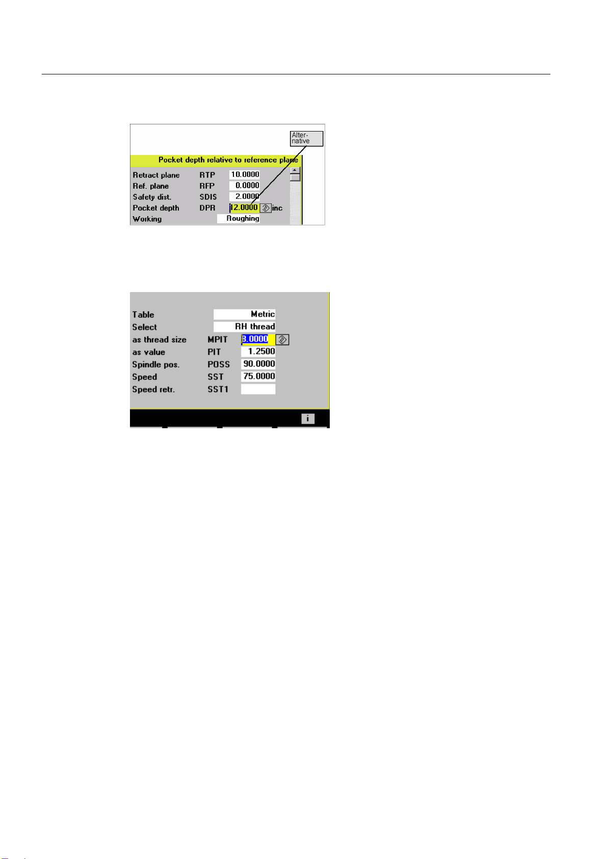
● One input may, therefore, automatically assign several dependent parameters. This is the
case for thread cutting, where metric thread tables are currently supported. During the
thread cutting cycle CYCLE97, for example, with input 12 in the input box for the thread
size (parameter MPIT), the thread pitch (parameter PIT) is automatically assigned a value
of 1.75 and the thread depth (parameter TDEP) is automatically assigned a value of
1.074. This function is not active if the metric thread table has not been selected.
● If a screen form is displayed a second time, the most recently entered values are
assigned to all fields. When cycles are called up several times in a row in the same
program (e.g., pocket milling when roughing and finishing), few parameters then have to
be changed.
● In screen forms for drilling and milling cycles, certain parameters may be input as
absolute or incremental values. The abbreviation ABS for absolute and INC for
incremental input is displayed behind the input field. This can be toggled with the
"Alternative" soft key. This setting will remain the next time these screen forms are called.
General
1.3 Cycle support in the program editor
Cycles
22 Programming Manual, 01/2008, 6FC5398-3BP20-1BA0
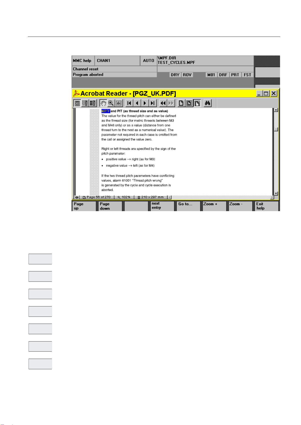
● HMI Advanced allows you to view additional information on each cycle parameter in the
online help. If the cursor is positioned on a parameter and the help icon appears in the
lower right corner, the help function can be activated.
By pressing the info key, the parameter explanation is displayed from the Cycle
Programming Guide.
General
1.3 Cycle support in the program editor
Cycles
Programming Manual, 01/2008, 6FC5398-3BP20-1BA0
23
Operating the help display
Paging backward in the documentation
Paging forward in the documentation
Enables the user to jump to another piece of text included in the help display
Enables the user to jump to a selected piece of text
Zoom the text in the help window
Reduce the text in the help window
Return to the cycle screen form
3DJH
XS
3DJH
GRZQ
1H[WHQWU\
*RWR
=RRP
=RRP
([LW
KHOS
General
1.3 Cycle support in the program editor
Cycles
24 Programming Manual, 01/2008, 6FC5398-3BP20-1BA0
Contour input support
Free contour programming
Starts the free contour programming, which can be used to enter contiguous contour
sections.
References: /BA/, Operator's Guide
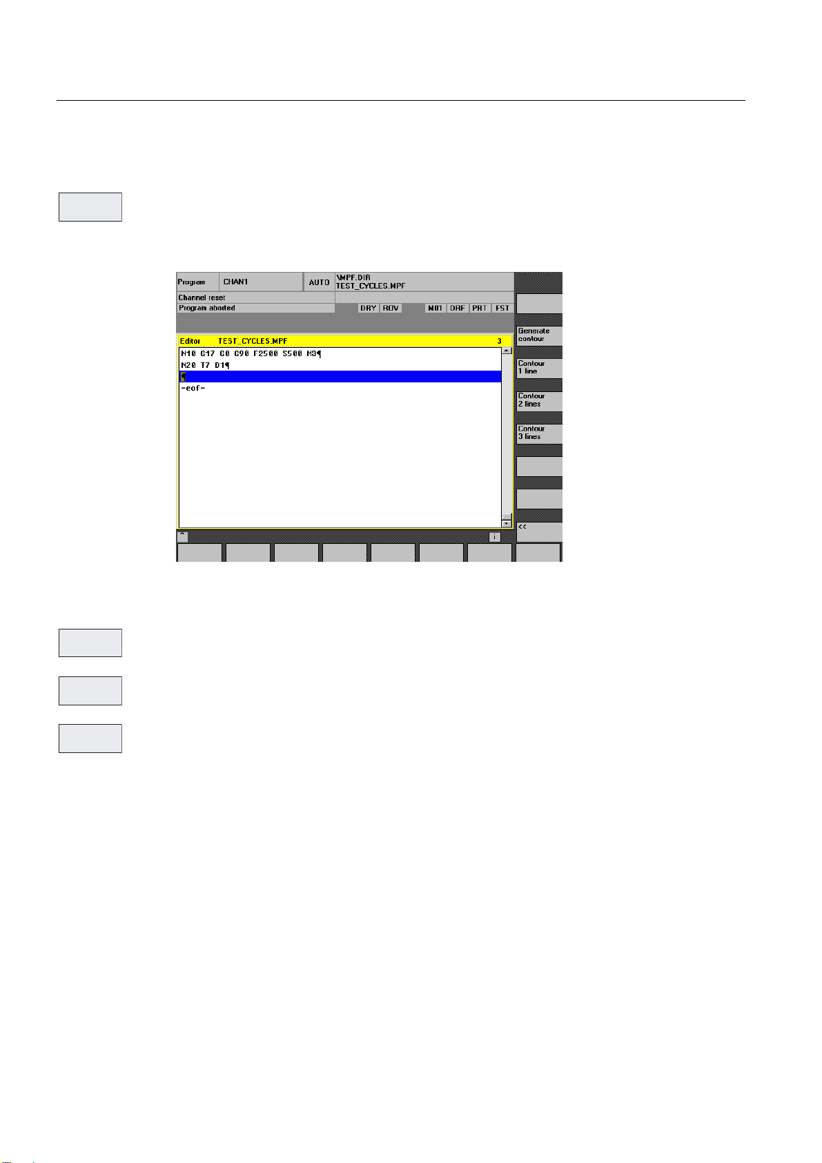
Contour definition programming
These soft keys support the contour definitions that are possible.
These consist of one or more straight lines with intermediary contour transition elements
(radii, chamfers). Each contour element may be preassigned by means of end points or point
and angle and supplemented by a free DIN code.
Example
The following DIN code is generated from the following input screen form for a contour
definition with two straight lines:
*HQHUDWH
FRQWRXU
&RQWRXU
OLQH
&RQWRXU
OLQH
&RQWRXU
OLQH
General
1.3 Cycle support in the program editor
Cycles
Programming Manual, 01/2008, 6FC5398-3BP20-1BA0
25
X=AC(20) ANG=87.3 RND=2.5 F2000 S500 M3
X=IC(10) Y=IC(-20); incremental end point
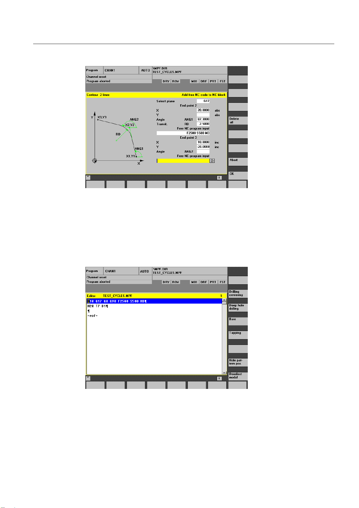
Drilling support
The drilling support includes a selection of drilling cycles and drilling patterns.

General
1.3 Cycle support in the program editor
Cycles
26 Programming Manual, 01/2008, 6FC5398-3BP20-1BA0
The "Drilling pattern position" soft key branches into a submenu with a selection of several
drilling patterns.
Selection of drilling patterns
Note
Cycles CYCLE81, CYCLE87 and CYCLE89 cannot be parameterized with this support. The
function of CYCLE81 is covered by CYCLE82 ("Drilling, centering" soft key), as is the
function of CYCLE89. The CYCLE87 function is covered by the function of CYCLE88 (soft
keys “Drilling center.” -> “Drilling with stop").
Drilling patterns may be repeated if, for example, drilling and tapping are to be executed in
succession. To this end, a name for the drilling pattern, which is later entered in the "Repeat
Position" screen form, is assigned in the drilling pattern.
Example with cycle support generated
N100 G17 G0 G90 Z20 F2000 S500 M3 ;Main block
N110 T7 M6 ;Change drilling machine
N120 G0 G90 X50 Y50 ;Initial drilling position
N130 MCALL CYCLE82(10,0,2,0,30,5) ;Modal drilling cycle call
N140 Circle of holes 1: ;Label – name of drilling pattern
N150 HOLES2(50,50,37,20,20,9) ;Call drilling pattern cycle
N160 ENDLABEL:
N170 MCALL ;Deselect modal call
N180 T8 M6 ;Change tap
N190 S400 M3
N200 MCALL CYCLE84(10,0,2,0,30,,→ ;Modal call of tapping cycle
→3,5,0.8,180,300,500)
N210 REPEAT Circle of holes 1 ;Repeat drilling pattern
N220 MCALL ;Deselect modal call
'ULOOLQJ
FHQWHULQJ
'HHSKROH
GULOOLQJ
%RUH
7DSSLQJ
+ROH
SDWWHUQSRV
'HVHOHFW
PRGDO

General
1.3 Cycle support in the program editor
Cycles
Programming Manual, 01/2008, 6FC5398-3BP20-1BA0
27
Moreover, any drilling position may be entered as a repeatable drilling pattern by means of
screen forms.
Up to 5 positions can be programmed in the plane; all values are optionally absolute or
incremental (can be toggled with "Alternative" soft key). The "Delete all" soft key generates
an empty screen form.
Milling support
Milling support includes the following selection possibilities:

General
1.3 Cycle support in the program editor
Cycles
28 Programming Manual, 01/2008, 6FC5398-3BP20-1BA0
The "Standard pockets", "Grooves", and "Spigot" soft keys each branch into submenus with
a selection of several pocket, groove, or spigot cycles.
)DFH
PLOOLQJ
6SLJRW
*URRYHV
6WDQGDUG
PLOOLQJ
3DWK
PLOOLQJ
7KUHDG
PLOOLQJ
6ZLYHOLQJ
F\FOHV
!!
Note
Pocket milling cycles POCKET1 and POCKET2 cannot be parameterized with this support.
Turning support
Turning support includes the following selection possibilities:
The undercut cycles for forms E and F (CYCLE94) as well as for the thread undercuts of
forms A to D (CYCLE96) are grouped together under the "Undercut" soft key.
The "Thread" soft key contains a submenu for selection between single thread cutting or
thread chaining.
7KUHDG
8QGHUFXW
*URRYH
&XW

General
1.3 Cycle support in the program editor
Cycles
Programming Manual, 01/2008, 6FC5398-3BP20-1BA0
29
Recompiling
Retranslating program codes serves to change an existing program with the help of cycle
support. The cursor is placed on the line to be changed, and the "Recompile" soft key is
pressed.
This reopens the corresponding input screen form, which created the program piece, and
values may be modified.
Entering modifications directly into the created DIN code may prevent recompilation.
Therefore, consistent use of the cycle support is required and modifications are to be carried
out with the help of recompilation.
Default settings for cycle support
Cycles SW 6.4 and higher includes a field for setting data _SC_MASK[10] for cycle support.
These are integer type data and are created as NCK global data in the GUD7_SC.DEF.
Date Value Meaning
_SC_MASK [0] - CYCLE84:
Default settings for the _TECHNO parameter
(set by the machine tool manufacturer during commissioning)
_SC_MASK [1] - CYCLE840:
Default settings for the _TECHNO parameter
(set by the machine tool manufacturer during commissioning)
CYCLE97:
0 Suggested values when using a metric thread table according
to DIN13-1 version 11.1999
_SC_MASK [2]
1 Suggested values when using a metric thread table according
to DIN13-1 version prior to 1999
(for backward compatibility of existing programs)
_SC_MASK [3 to 9] internal
Support for programming user cycles
References: /IAM/, HMI Installation and Startup Guide
BE1 "Expanding the User Interface"
IM2 "Startup of HMI Embedded"
IM4 "Startup of HMI Advanced"

General
1.4 Cycle support for user cycles
Cycles
30 Programming Manual, 01/2008, 6FC5398-3BP20-1BA0
1.4 Cycle support for user cycles
1.4.1 Overview of necessary files
The following files constitute the basis for cycle support:
Assignment File Application File type
aeditor.com Standard and user cycles Text file Cycle selection
common.com
(HMI Embedded only)
Standard and user cycles Text file
Input screen form for
parameter assignment
*.com Standard or user cycles Text file
Help screens *.bmp Standard or user cycles Bitmap
Online help
(HMI Advanced only)
pgz_<language>.pdf and
pgz_<language>.txt
Standard cycles only pdf file
Note
Any names can be chosen for the cycle support configuration files (*.com ).
1.4.2 Getting started with cycle support
Function
The horizontal soft key HS6 in the program editor is designated as the Entry soft key for user
cycles. Its function must be configured in file aeditor.com. Assign a text to the soft key and
configure a function in the press block for soft key operation.
Example
//S(Start)
...
HS5=($80270,,se1)
PRESS(HS5)
LS("Turning",,1)
END_PRESS
HS6=("Usercycle",,se1) ;HS6 is configured with the "Usercycle" text
PRESS(HS6)
LS("SK_Cycles1","cycproj1") ;When the soft key is pressed, a soft key bar is
;loaded from the file cycproj1.com
END_PRESS
A detailed description of the configuration is given in:
References: /IAM/, HMI Installation and Startup Guide: BE1 "Expanding the User Interface"
Loading...